Most of UMTS Cell support both CS and PS communication, but there are some cases where a cell support or allow only CS or PS communication.
How Network can inform UE of its CN (Core Network) capability ?
The first level information about CN capability is sent to UE by System Information Type 1.
Would this capability influence on Registration protocol sequence ?
Yes. There are roughly three different types of registration sequence being used for each of CN configuration.
Of course, in real network you would see various variation.. but these three type of sequence would give you a good template for each case.
This page first reads the CN domain list of SIB1 in three captures. It then decodes the NAS system information inside that list, because those bytes decide which registration sequence applies. The last section lists the three registration sequences.
- System Information Type 1
- How does the UE decode the CN domain information?
- Registration Sequence
- Reference
System Information Type 1
SIB1 answers the question from the introduction. Its field cn-DomainSysInfoList holds one entry for each CN domain that the cell supports. So the number of entries and their cn-DomainIdentity values tell the UE which domains it can register with.
Following SIB1 shows the case where the cell support both CS and PS capability. In this case, usually Registration procedure < Type 1 > in case of Non Combined (NMO II) registration or < Type 3 > in case of Combined (NMO I) is used.
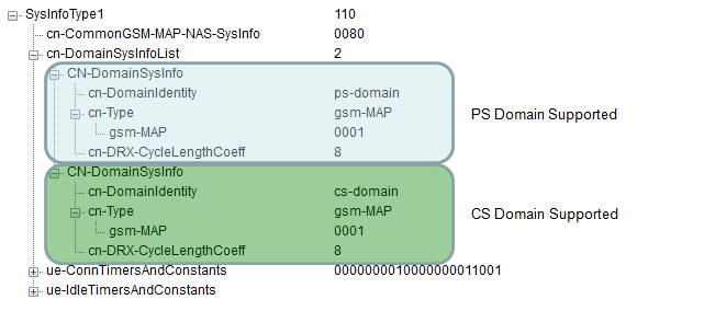
Two entries in cn-DomainSysInfoList mean that the cell supports both the CS domain and the PS domain.
cn-DomainSysInfoList has 2 entries : one for ps-domain and one for cs-domain.cn-Type is gsm-MAP in both entries : each entry carries two octets of NAS system information, 0001.cn-DRX-CycleLengthCoeff is 8 in both entries : each domain has its own paging DRX cycle, and here both are 256 frames.cn-CommonGSM-MAP-NAS-SysInfo is 0080 : this is the LAC, shared by both domains.
The PS entry of this capture indicates NMO II, as the next section decodes. So this cell uses the non-combined registration, Type 1.
Following SIB1 shows the case where the cell support PS capability only. In this case, usually Registration procedure < Type 3 > is used.
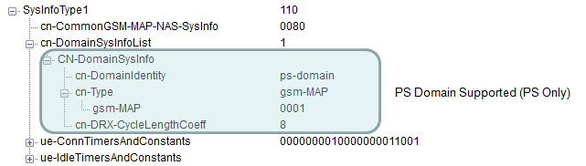
One entry with ps-domain means that the cell offers only the PS domain, so the UE performs only the GPRS attach.
Following SIB1 shows the case where the cell support CS capability only. In this case, usually Registration procedure < Type 2 > is used.
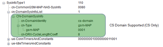
One entry with cs-domain means that the cell offers only the CS domain, so the UE performs only the location update.
The list length gives the number of domains : one entry for a CS only or PS only cell, two entries for a CS and PS cell.cn-DomainIdentity names the domain : cs-domain or ps-domain.The entries have the same structure : only the meaning of the NAS octets differs between the domains.
How does the UE decode the CN domain information?
The SIB1 captures show short hex strings such as 0080 and 0001. RRC does not define what is inside them. 25.331 carries them as NAS-SystemInformationGSM-MAP, an OCTET STRING, and 24.008 defines the bits.
The tile below gives the SIB1 fields that carry this information. CN-DomainIdentity has only two values, cs-domain and ps-domain, although maxCNdomains allows up to 4 entries in the list.
Following is based on
SysInfoType1 ::=                    SEQUENCE {
    -- Core network IEs
        cn-CommonGSM-MAP-NAS-SysInfo    NAS-SystemInformationGSM-MAP,
        cn-DomainSysInfoList            CN-DomainSysInfoList,
    -- User equipment IEs
        ue-ConnTimersAndConstants       UE-ConnTimersAndConstants           OPTIONAL,
        ue-IdleTimersAndConstants       UE-IdleTimersAndConstants           OPTIONAL,
    -- Extension mechanism for non- release99 information
        v3a0NonCriticalExtensions       SEQUENCE {
            sysInfoType1-v3a0ext            SysInfoType1-v3a0ext-IEs,
            v860NonCriticalExtentions       SEQUENCE {
                sysInfoType1-v860ext            SysInfoType1-v860ext-IEs,
                nonCriticalExtensions           SEQUENCE {} OPTIONAL
            }                           OPTIONAL
        }                           OPTIONAL
}

CN-DomainSysInfoList ::=            SEQUENCE (SIZE (1..maxCNdomains)) OF
                                        CN-DomainSysInfo

CN-DomainSysInfo ::=                SEQUENCE {
    cn-DomainIdentity                   CN-DomainIdentity,
    cn-Type                             CHOICE {
        gsm-MAP                             NAS-SystemInformationGSM-MAP,
        ansi-41                             NAS-SystemInformationANSI-41
    },
    cn-DRX-CycleLengthCoeff             CN-DRX-CycleLengthCoefficient
}

CN-DomainIdentity ::=               ENUMERATED {
                                        cs-domain,
                                        ps-domain }

NAS-SystemInformationGSM-MAP ::=    OCTET STRING (SIZE (1..8))

CN-DRX-CycleLengthCoefficient ::=   INTEGER (6..9)
Let's decode the three octet strings of the first capture with 24.008. The field cn-CommonGSM-MAP-NAS-SysInfo holds the LAC in two octets. The captured value 0080 is LAC 0x0080, which is 128.
For the CS domain, the first octet is T3212 in decihours. Bit 1 of the second octet is the ATT flag. The captured 0001 gives T3212 = 0, which means that periodic location updating is not used. It also gives ATT = 1, which means that the UE shall apply IMSI attach and detach.
For the PS domain, the first octet is the RAC. In the second octet, bit 1 is NMO: 0 means Network Mode of Operation I, and 1 means NMO II. Bit 2 is NMO I, which applies only to a UE configured for NMO_I_Behaviour. The captured 0001 gives RAC = 0 and NMO = 1, so the network runs in NMO II.
This bit links SIB1 to the registration sequences. In NMO II, the UE registers separately in each domain, with a Location Updating Request for CS and an Attach Request for PS. That is Type 1. In NMO I, the UE sends one Attach Request with the attach type combined GPRS/IMSI attach, and Attach Accept answers for both domains. That is why a combined registration follows the message flow of Type 3.
The last field is the DRX coefficient k. The UE sets the CN domain DRX cycle to MAX(2k, PBP) frames, and PBP is 1 for FDD. With k = 8, the UE checks for paging every 256 frames, which is 2.56 seconds. The allowed range of 6 to 9 gives cycles from 0.64 to 5.12 seconds.
The common field holds the LAC : 0080 is LAC 128.The CS field holds T3212 and ATT : 0001 means no periodic update, and IMSI attach and detach are applied.The PS field holds the RAC and NMO : 0001 means RAC 0 and NMO II.NMO selects the sequence : NMO II gives Type 1, and NMO I gives a combined attach with the flow of Type 3.k = 8 gives a 2.56 second DRX cycle : the cycle is 2k frames of 10 ms.
Registration Sequence
Each sequence below runs on one RRC connection, from RRC Connection Request to RRC Connection Release Complete. The NAS messages inside the direct transfers are what differ. MM messages go to the CS domain, and GMM messages go to the PS domain.
Type 1
Type 1 is the non-combined case, used when the cell supports both domains in NMO II. The UE runs a location update and a GPRS attach on the same RRC connection. The two procedures overlap: the Attach Request at step 6 goes out before the MM authentication ends at step 7. Each domain then runs its own Security Mode Command.
1) RRC: RRC Connection Request
2) RRC: RRC Connection Setup
3) RRC: RRC Connection Setup Complete
4) RRC: initialDirectTransfer + MM: Location Updating Request
5) RRC : downlinkDirectTransfer + MM:Authentication Request
6) RRC: initialDirectTransfer + GMM: Attach Request
7) RRC : uplinkDirectTransfer + MM:Authentication Response
8) RRC : Security Mode Command
9) RRC : Security Mode Complete
10) RRC : downlinkDirectTransfer + MM:Identity Request
11) RRC : uplinkDirectTransfer + MM:Identity Response
12) RRC : downlinkDirectTransfer + MM:Location Updating Accept
13) RRC : uplinkDirectTransfer + MM:TMSI Reallocation Complete
14) RRC : downlinkDirectTransfer + GMM: AuthenticationAndCipheringRequest
15) RRC : uplinkDirectTransfer + GMM: AuthenticationAndCipheringResponse
16) RRC : Security Mode Command
17) RRC : Security Mode Complete
18) RRC : downlinkDirectTransfer + GMM:Identity Request
19) RRC : uplinkDirectTransfer + GMM:Identity Response
20) RRC : downlinkDirectTransfer + GMM:Attach Accept
21) RRC : uplinkDirectTransfer + GMM:Attach Complete
22) RRC : RRC Connection Release
23) RRC : RRC Connection Release Complete
Type 2
Type 2 is the CS only case. Only the MM part of Type 1 is left: location update, authentication, security mode, identity request and TMSI reallocation. No GMM message appears.
1) RRC: RRC Connection Request
2) RRC: RRC Connection Setup
3) RRC: RRC Connection Setup Complete
4) RRC: initialDirectTransfer + MM: Location Updating Request
5) RRC : downlinkDirectTransfer + MM:Authentication Request
6) RRC : uplinkDirectTransfer + MM:Authentication Response
7) RRC : Security Mode Command
8) RRC : Security Mode Complete
9) RRC : downlinkDirectTransfer + MM:Identity Request
10) RRC : uplinkDirectTransfer + MM:Identity Response
11) RRC : downlinkDirectTransfer + MM:Location Updating Accept
12) RRC : uplinkDirectTransfer + MM:TMSI Reallocation Complete
13) RRC : RRC Connection Release
14) RRC : RRC Connection Release Complete
Type 3
Type 3 is the PS only case, and it is also the message flow of a combined attach in NMO I. Only the GMM part of Type 1 is left. In the combined case, the Attach Request carries the attach type combined GPRS/IMSI attach.
1) RRC: RRC Connection Request
2) RRC: RRC Connection Setup
3) RRC: RRC Connection Setup Complete
4) RRC: initialDirectTransfer + GMM: Attach Request
5) RRC : downlinkDirectTransfer + GMM: AuthenticationAndCipheringRequest
6) RRC : uplinkDirectTransfer + GMM: AuthenticationAndCipheringResponse
7) RRC : Security Mode Command
8) RRC : Security Mode Complete
9) RRC : downlinkDirectTransfer + GMM:Identity Request
10) RRC : uplinkDirectTransfer + GMM:Identity Response
11) RRC : downlinkDirectTransfer + GMM:Attach Accept
12) RRC : uplinkDirectTransfer + GMM:Attach Complete
13) RRC : RRC Connection Release
14) RRC : RRC Connection Release Complete
Type 1 runs MM and GMM in parallel : each domain has its own authentication and its own Security Mode Command.Type 2 is MM only : the cell offers only the CS domain.Type 3 is GMM only : a PS only cell, or a combined attach in NMO I.
Reference
[1] 3GPP TS 25.331 v19.0.1 - clause 10.3.1.1, CN domain identity, clause 10.3.1.2, CN Domain System Information, clause 8.6.3.1a, CN domain specific DRX cycle length coefficient, and the ASN.1 of clause 11
[2] 3GPP TS 24.008 v20.0.0 - clause 10.5.1.12, Core Network System Information