A UE never reports CPICH Ec/Io in dB. It reports an integer, and the network converts that integer with a table in 25.133. Let's look at where the value appears, how to convert it, and what the UE actually measures to produce it.
- Where does the UE report CPICH Ec/Io ?
- How is the reported value converted to dB ?
- What does the UE measure as CPICH Ec/Io ?
- Reference
Where does the UE report CPICH Ec/Io ?
The first place to meet this value is the RRC Connection Request, before the UE has any dedicated connection. So the network learns the quality of the cell at the very first message. The same integer format appears later in measurement reports.
RRC Connection Request and some Measurement Report message carries the CPICH measured value as follows. But the value itself is not a dB or dBm value. There is a predefined table that maps this value to the real dB value.
Decoded RRC message from a tester log,
    +-rrcConnectionRequest ::= SEQUENCE [11]
      +-initialUE-Identity ::= CHOICE [tmsi-and-LAI]
      +-establishmentCause ::= ENUMERATED [registration]
      +-protocolErrorIndicator ::= ENUMERATED [noError]
      +-measuredResultsOnRACH ::= SEQUENCE [0] OPTIONAL:Exist
      | +-currentCell ::= SEQUENCE
      | | +-modeSpecificInfo ::= CHOICE [fdd]
      | |   +-fdd ::= SEQUENCE
      | |     +-measurementQuantity ::= CHOICE [cpich-Ec-N0]
      | |       +-cpich-Ec-N0 ::= INTEGER (0..63) [41]
The capture is short, so let's read it line by line. The UE sends RRC Connection Request for registration, with a TMSI and LAI as its identity. It includes the optional measuredResultsOnRACH, and the lines in red show the result for the current cell. The measurement quantity is cpich-Ec-N0, and the reported value is 41.
The decoder shows the range as INTEGER (0..63), while the table in the next section ends at 49. Both are correct, as the ASN.1 below shows. 25.331 defines CPICH-Ec-N0 as INTEGER (0..63) and marks the values above 49 as spare. So a UE sends only 0 to 49, even though the encoding has room for 64 values.
Following is based on
-- SPARE: CPICH-Ec-No, Max = 49
-- Values above Max are spare
CPICH-Ec-N0 ::=						INTEGER (0..63)

MeasuredResultsOnRACH ::=			SEQUENCE {
	currentCell 						SEQUENCE {
		modeSpecificInfo					CHOICE {
			fdd									SEQUENCE {
				measurementQuantity					CHOICE {
					cpich-Ec-N0							CPICH-Ec-N0,
					cpich-RSCP							CPICH-RSCP,
					pathloss							Pathloss,
					cpich-Ec-N0-RSCP					CPICH-Ec-N0-RSCP
				}
			},
			tdd									SEQUENCE {
				-- For 3.84 Mcps, 7.68 Mcps and 1.28 Mcps TDD
				timeslotISCP						TimeslotISCP-List		OPTIONAL,
				primaryCCPCH-RSCP					PrimaryCCPCH-RSCP		OPTIONAL
			}
		}
	},
	monitoredCells						MonitoredCellRACH-List				OPTIONAL
}
The ASN.1 also shows that cpich-Ec-N0 is only one choice of measurementQuantity. The network tells the UE in system information which quantity to report on RACH. The UE can report CPICH RSCP, pathloss, or both Ec/N0 and RSCP instead. Note also the naming: 25.331 writes Ec/N0 in the field name, while 25.133 writes Ec/Io in the table, and both mean the same measurement.
The RACH report comes before any connection : the network sees the cell quality in RRC Connection Request.0..63 in the decoder is the ASN.1 range : values 50 to 63 are spare, and the real range is 0 to 49.Check the measurement quantity first : the same field position can carry Ec/N0, RSCP or pathloss.
How is the reported value converted to dB ?
Now we need the table that turns 41 into a number in dB. The reporting range is -24 to 0 dB in steps of 0.5 dB. The table gives a range for each integer, not a single value, and that matters when you compare logs.
Following table comes from 3GPP 25.133.
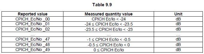
25.133 Table 9.9. CPICH Ec/Io measurement report mapping. Each reported value covers a 0.5 dB range, with open ranges at both ends.
- CPICH_Ec/No _00 means CPICH Ec/Io below -24 dB.
- CPICH_Ec/No _01 to _48 each cover 0.5 dB, from -24 dB up to 0 dB.
- CPICH_Ec/No _49 means CPICH Ec/Io of 0 dB or more.
The rows in the middle follow one rule. For a reported value N from 1 to 48, the lower edge of the range is -24.5 + 0.5 x N dB. The upper edge is 0.5 dB higher, and the range does not include it. For the capture above, N = 41 gives -24.5 + 20.5 = -4 dB. So the UE measured CPICH Ec/Io between -4 dB and -3.5 dB.
A quick way to convert in your head is to halve the reported value and subtract 24.5. That gives the lower edge of the range. The table below lists a few values that often appear in logs.
Reported value | CPICH Ec/Io - dB |
0 | Ec/Io < -24 |
1 | -24 <= Ec/Io < -23.5 |
9 | -20 <= Ec/Io < -19.5 |
17 | -16 <= Ec/Io < -15.5 |
25 | -12 <= Ec/Io < -11.5 |
33 | -8 <= Ec/Io < -7.5 |
41 | -4 <= Ec/Io < -3.5 |
48 | -0.5 <= Ec/Io < 0 |
49 | 0 <= Ec/Io |
The accuracy of the measurement is a separate question from the mapping. 25.133 Table 9.5 gives the intra frequency absolute accuracy, which is +/-1.5 dB in the best part of the range and wider at lower Ec/Io. So a change of one or two reported steps can be measurement error rather than a real change in the cell.
The reported value is a range : 41 means a value from -4 dB to just below -3.5 dB, and it does not mean -4 dB exactly.Halve and subtract 24.5 : that gives the lower edge of the range for values 1 to 48.Steps are finer than the accuracy : the 0.5 dB step is smaller than the +/-1.5 dB absolute accuracy.
What does the UE measure as CPICH Ec/Io ?
A reported value is useful only if we know what quantity sits behind it. 25.215 defines CPICH Ec/No as a ratio of two other measurements. Knowing that ratio explains why Ec/Io behaves differently from RSCP when the cell gets loaded.
In 25.215, CPICH Ec/No is the received energy per chip divided by the power density in the band. Without receiver diversity, it is identical to CPICH RSCP divided by UTRA Carrier RSSI. The UE measures it on the Primary CPICH at the antenna connector. With Tx diversity on the P-CPICH, the UE measures Ec from each antenna and sums them before it forms the ratio.
This ratio explains a common observation. RSCP measures only the CPICH, so it depends mainly on path loss. RSSI includes the whole received band, so it rises when the serving cell or a neighbour cell carries more traffic. Ec/Io therefore falls with load, even when the UE does not move. Let's take a simple example. The P-CPICH carries 10 percent of the transmit power of a cell, and the UE hears only that cell with no noise. Then Ec/Io is about -10 dB, even though the signal is perfectly clean.
RSCP has its own mapping in 25.133 Table 9.4, in 1 dB steps. The reporting range is -120 dBm to -25 dBm, and the table ends at CPICH_RSCP_LEV _91 for -25 dBm or more. In the current release, the table starts at CPICH_RSCP_LEV _-05. 25.331 carries these low values in the separate IE DeltaRSCP, which is INTEGER (-5..-1).
Ec/Io is RSCP over RSSI : it tells you about both the signal and the interference, not about the signal alone.Ec/Io falls with load : a lower value at the same location often means more traffic, not more path loss.Use RSCP for coverage and Ec/Io for quality : the two measurements together separate a weak signal from a busy cell.
Reference
- 3GPP TS 25.133 v19.0.0 - subclause 9.1.1.3 CPICH RSCP measurement report mapping, 9.1.2 CPICH Ec/Io, Table 9.5 and Table 9.9
- 3GPP TS 25.215 v19.0.0 - subclause 5.1.5 CPICH Ec/No
- 3GPP TS 25.331 v19.0.1 - CPICH-Ec-N0, MeasuredResultsOnRACH, DeltaRSCP