After the cell search, the UE knows where the slots and frames of the cell start. It does not yet know where each channel starts, because the downlink channels of one cell do not all begin at the same instant. Each channel sits at a fixed or signalled offset from one common frame. Let's see how the UE works out those offsets, one channel group at a time.
Once you complete the cell search process described above, UE can figure out the following information about the timing.
i) Exact phase reference for downlink channels from CPICH (This is not the timing parameter, but this would very important factors to decode other channels including Timing/Sync related channels).
ii) Exact start timing of each slots from P-SCH
iii) Exact start timing of each frame from S-SCH
iv) System Frame Number for each frame from P-CCPCH (SFN and MIB) // This becomes the timing reference
The rest of this page takes the channels in the order the UE meets them. The common channels come first, then the paging channels, then the dedicated channels and finally random access.
- Which channel is the timing reference ?
- How are the S-CCPCH and PICH offsets signalled ?
- How is the DPCH timing set, and how does the uplink follow it ?
- How are the PRACH and the AICH aligned ?
- Reference
Which channel is the timing reference ?
Every downlink channel needs a start point, and 25.211 gives all of them the same one. The P-CCPCH carries the SFN on the BCH, so its frame boundary is the zero point for every other offset in the cell.
Once UE get all the information listed above, the timing for other channels can be deduced by the following diagram (This diagram came from 3GPP TS 25.211).
P-CCPCH carries SFN and this becomes the timing reference for all downlink channels and it also become the timing reference for uplink channels in indirect way.
For example, S-CCPCH is transmitted at the multiples of 256 chips delay from the start of CPICH(Start of frame timing). And PICH is transmitted at the specified timing before S-CCPCH.
For the details of these timing value, refer to 25.211 - 7 Timing relationship between physical channels - 7.1 General
Some of these timing offsets are set by higher layer signaling message (e.g, SIB, RRC Connection Setup, Radio Bearer Setup).
S-CCPCH TimingOffset is specified by SIB5 elements : sCCPCH-SystemInformationList.SCCPCH-SystemInformation[0].secondaryCCPCH-Info.modeSpecificInfo.fdd.timingOffset
The diagram below is 25.211 Figure 29. Each row is one channel, and each arrow such as τS-CCPCH,k or τDPCH,n is an offset measured from the start of the P-CCPCH frame. The P-CCPCH row is split into frames with SFN modulo 2 = 0 and SFN modulo 2 = 1, because the 15 AICH access slots span two frames.
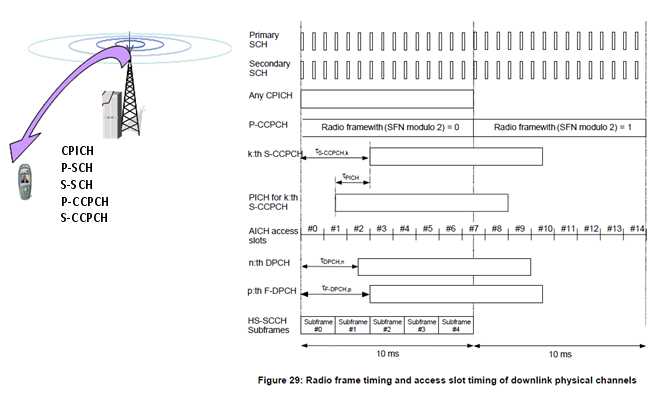
25.211 Figure 29. SCH, CPICH, P-CCPCH and HS-SCCH subframe #0 start together. S-CCPCH, DPCH and F-DPCH are shifted by their own offsets, while PICH and AICH follow fixed rules.
Some important characteristics of these channel timing are as follows : (This is based 25.211 7.1 General)
- SCH (primary and secondary), CPICH (primary and secondary) and P-CCPCH have identical frame timings
- The S-CCPCH timing may be different for different S-CCPCHs, but the offset from the P-CCPCH frame timing is a multiple of 256 chips
- If the PICH is associated to the S-CCPCH, the PICH timing is τPICH = 7680 chips prior to its corresponding SCCPCH frame timing and If the PICH is associated to the HS-SCCH, the PICH frame timing is the same as the HS-SCCH frame timing.
- AICH access slots #0 starts the same time as P-CCPCH frames with (SFN modulo 2) = 0.
- The DPCH timing may be different for different DPCHs, but the offset from the P-CCPCH frame timing is a multiple of 256 chips.
- The F-DPCH timing may be different for different F-DPCHs, but the offset from the P-CCPCH frame timing is a multiple of 256 chips.
- The start of HS-SCCH subframe #0 is aligned with the start of the P-CCPCH frames.
- For a secondary serving HS-DSCH cell, the nominal radio frame timing for CPICH and timing reference are the same as the radio frame timing for CPICH and timing reference for the serving HS-DSCH cell
The offsets in the list are written as τS-CCPCH,k = Tk x 256 chip, τDPCH,n = Tn x 256 chip and τF-DPCH,p = Tp x 256 chip. Each T value runs from 0 to 149. So the largest offset is 149 x 256 = 38144 chips, one step short of the 38400-chip radio frame. An S-CCPCH that carries the BCH always uses Tk = 0.
25.211 v19.0.0 also extends the list above. The demodulation CPICH joins the group with identical frame timing. The F-TPICH, which carries the precoding indicator for uplink CLTD, follows the same 256-chip rule as DPCH and F-DPCH. All F-DPCHs sent to one UE from the same HS-DSCH cell set have the same timing.
The P-CCPCH frame is the zero point : every downlink offset is measured from its start, and the uplink timing follows the received downlink.Offsets come in 256-chip steps : S-CCPCH, DPCH, F-DPCH and F-TPICH use T x 256 chips, with T from 0 to 149.PICH and AICH use fixed rules : the PICH is tied to its S-CCPCH or HS-SCCH, and the AICH is tied to SFN modulo 2.
How are the S-CCPCH and PICH offsets signalled ?
A UE in idle mode has no dedicated signalling, but it still has to find its paging channel. So the S-CCPCH offset must come from system information, and the PICH timing must follow from it by a fixed rule.
The network sends the offset in SIB5, inside the SecondaryCCPCH-Info of each entry in sCCPCH-SystemInformationList. The IE is timingOffset, and 25.331 defines its actual value as the IE value x 256 chips. The ASN.1 below shows the path from SCCPCH-SystemInformation down to that field.
Following is based on
SCCPCH-SystemInformation ::=		SEQUENCE {
	secondaryCCPCH-Info				SecondaryCCPCH-Info,
	tfcs								TFCS								OPTIONAL,
	fach-PCH-InformationList			FACH-PCH-InformationList			OPTIONAL,
	pich-Info							PICH-Info							OPTIONAL
}

SecondaryCCPCH-Info ::=		SEQUENCE {
	modeSpecificInfo				CHOICE {
		fdd								SEQUENCE {
			-- dummy1 is not used in this version of the specification and should be ignored.
			dummy1							PCPICH-UsageForChannelEst,
			-- dummy2 is not used in this version of the specification.  It should not
			-- be sent and if received it should be ignored.
			dummy2							SecondaryCPICH-Info				OPTIONAL,
			secondaryScramblingCode			SecondaryScramblingCode			OPTIONAL,
			sttd-Indicator					BOOLEAN,
			sf-AndCodeNumber				SF256-AndCodeNumber,
			pilotSymbolExistence			BOOLEAN,
			tfci-Existence					BOOLEAN,
			positionFixedOrFlexible		PositionFixedOrFlexible,
			timingOffset					TimingOffset					DEFAULT 0
		},
		tdd 							SEQUENCE {
			-- TABULAR: the offset is included in CommonTimeslotInfoSCCPCH
			commonTimeslotInfo				CommonTimeslotInfoSCCPCH,
			individualTimeslotInfo		IndividualTimeslotInfo,
			channelisationCode				SCCPCH-ChannelisationCodeList
		}
	}
}

-- Actual value TimingOffset = IE value * 256
TimingOffset ::=					INTEGER (0..149)
The default is 0, so an S-CCPCH without the field starts with the P-CCPCH frame. The same SCCPCH-SystemInformation also carries pich-Info. Each S-CCPCH that carries a PCH therefore comes with its own PICH.
The PICH offset itself is never signalled. 25.211 fixes it at τPICH = 7680 chips before the S-CCPCH frame, which is 3 slots or 2 ms. A paging indicator set in a PICH frame means that the paging message is sent on the PCH in the S-CCPCH frame that starts τPICH chips later. The 2 ms gap lets the UE detect its paging indicator before the S-CCPCH frame starts. When the indicator is not set, the UE can skip that S-CCPCH frame.
The rule is different when the PICH is associated with the HS-SCCH, which is the case when paging is carried on HS-DSCH. The PICH frame then has the same timing as the HS-SCCH frame. Each PICH frame has 5 associated HS-SCCH subframes, and the first of them starts one subframe after the PICH frame. That first subframe is HS-SCCH subframe #1.
timingOffset is in units of 256 chips : INTEGER (0..149) per S-CCPCH, sent in SIB5, with a default of 0.The PICH leads its S-CCPCH by 7680 chips : this is 2 ms, fixed in 25.211 and never signalled.Paging on HS-DSCH changes the rule : the PICH is aligned with the HS-SCCH frame, and the paged subframes start one subframe later.
How is the DPCH timing set, and how does the uplink follow it ?
Dedicated channels are placed by the RNC for each UE rather than broadcast. The RNC spreads the DPCH frames of different UEs across the frame, so that DTX periods and Iub traffic are not all aligned in time.
Two IEs carry this timing in the message that moves the UE to CELL_DCH, such as RRC Connection Setup or Radio Bearer Setup. The first is DPCH frame offset, sent per radio link. Its range is 0 to 38144 chips in steps of 256, and it is τDPCH,n of 25.211. The second is Default DPCH Offset Value, DOFF, from 0 to 599 in units of 512 chips. DOFF offsets the CFN in the UE.
The two are not independent. For a single radio link with DPCH, UTRAN sets them so that (Default DPCH Offset Value) mod 38400 = DPCH frame offset. With F-DPCH, UTRAN may also use (Default DPCH Offset Value + 256) mod 38400 = DPCH frame offset. With several radio links, the relation applies to the first radio link in the message.
Following is based on
-- Actual value DPCH-FrameOffset = IE value * 256
DPCH-FrameOffset ::=				INTEGER (0..149)

-- DefaultDPCH-OffsetValueFDD and DefaultDPCH-OffsetValueTDD corresponds to
-- IE "Default DPCH Offset Value" depending on the mode.
-- Actual value DefaultDPCH-OffsetValueFDD = IE value * 512

DefaultDPCH-OffsetValueFDD ::=		INTEGER (0..599)
The uplink has no offset IE of its own. The UE starts its uplink DPCCH/DPDCH frame about T0 = 1024 chips after the first detected path of the downlink DPCH or F-DPCH frame. So a change of the downlink DPCH offset moves the uplink frame by the same amount. This is what 25.211 means when it calls the P-CCPCH the timing reference for the uplink in an indirect way.
DPCH frame offset is per radio link : 0 to 38144 chips in steps of 256.DOFF shifts the CFN : 0 to 599 in units of 512 chips, and it matches the DPCH frame offset modulo 38400.The uplink follows the downlink : the uplink DPCCH/DPDCH starts T0 = 1024 chips after the received downlink frame.
How are the PRACH and the AICH aligned ?
Random access is the one exchange where the UE transmits before it has any dedicated timing. The UE therefore takes its uplink access slots from the downlink AICH, and the AICH takes its access slots from the P-CCPCH.
The AICH is divided into access slots of 5120 chips, which is two slots. Fifteen access slots fill two radio frames, or 20 ms. Access slot #0 starts with a P-CCPCH frame that has SFN modulo 2 = 0. The PRACH uses the same access slot numbering. The UE sends uplink access slot n τp-a chips before it receives downlink access slot n.
The network chooses between two timing sets with AICH_Transmission_Timing. It is sent as aich-TransmissionTiming, e0 or e1, in the AICH-Info of the PRACH system information. The table below lists the three distances for each value.
AICH_Transmission_Timing |
τp-p,min |
τp-a |
τp-m |
0 |
15360 chips, 3 access slots |
7680 chips |
15360 chips, 3 access slots |
1 |
20480 chips, 4 access slots |
12800 chips |
20480 chips, 4 access slots |
τp-p,min is the minimum distance between two preambles. τp-a runs from a preamble to its acquisition indicator, and τp-m runs from the preamble to the message part. The value 1 gives the Node B more time to detect a preamble, but every access attempt takes longer.
Following is based on
AICH-Info ::=						SEQUENCE {
	channelisationCode256				ChannelisationCode256,
	sttd-Indicator						BOOLEAN,
	aich-TransmissionTiming				AICH-TransmissionTiming
}

AICH-TransmissionTiming ::=			ENUMERATED {
										e0, e1 }
An access slot is 5120 chips : 15 access slots span two frames, starting at SFN modulo 2 = 0.e0 gives 7680 chips, e1 gives 12800 chips : this is the preamble to AI distance τp-a.The PRACH timing comes from the AICH : the UE counts its uplink access slots from the received downlink access slots.
Reference
[1] 3GPP TS 25.211 v19.0.0 - clause 7, Timing relationship between physical channels
[2] 3GPP TS 25.331 v19.0.1 - clauses 8.6.6.14 and 10.3.6.16, and the ASN.1 of clause 11.3