MAC-c/sh/m is the MAC entity that handles the common transport channels of UMTS. On the UTRAN side it sits in the controlling RNC, and there is one per cell. On the UE side there is one per UE. It maps PCCH, BCCH and CCCH onto PCH, FACH and RACH, and it also carries DCCH and DTCH when a UE in CELL_FACH uses RACH and FACH.
This page follows the 25.321 architecture figures for both sides, one path at a time, and ties each path to the MAC header it produces. It ends with the RACH transmission control that only the UE side runs.
Followings are the topics to be covered in this page.
- Overview on MAC-c/sh/m in UTRAN
- Overview on MAC-c/sh/m in UE
- How does MAC-c/sh/m control a RACH transmission ?
- Reference
Overview on MAC-c/sh/m in UTRAN
Now let's look into MAC-c/sh/m moudle in UTRAN MAC. It looks pretty complicated and intimidating ? Well... let's just pick what we are interested in for now as I suggested above.
Now.. I am only interested in FDD. TDD is not my interest now.
CTCH (mainly for Cell Broadcasting) is not may interest either for now.
With this focusing, we only have the path marked with red lines.
Does this look simpler to you ? I hope you say "YES".
One thing you have to notice in this diagram is that the line does not have any arrow head. It does not mean that the line is always bidirection. Some line means uni-directional and some line means bi-directional. In this case, PCCH and BCCH are unidirectional, downlink only. CCCH is bidirectional which means both for downlink and uplink.
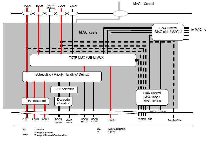
< 25.321 - Figure 4.2.4.1-1 : UTRAN side MAC architecture / MAC-c/sh/m details >
Another tip of understanding this diagram is to correlate this diagram to MAC PDU structure of each channel that is following this diagram (In 25.321, they are quite a far apart.. so you may lose mental connection between the two).
The end result of most of the procedure shown in the above figure is adding or removing a special portions in MAC header.
The first path we are thinking of is PCCH path which is downlink only and carries Paging message (Paging Type 1). 25.321 9.2.1.3 MAC header for PCCH says "There is no MAC header for PCCH when mapped on PCH". (The spec says PCH would have MAC-ehs when the PCH is mapped on HS-DSCH, but this does not happen in the MAC component being discussed in this section).
Next path is BCCH path which is downlink only and carries MIB and SIBs. It can create one of the following three cases, but the case produced by the MAC component shown in this section is Case b), because MAC-c/sh/m carries BCCH on FACH. I means that the TCTF MUX block adds the TCTF 00 in front of the MAC SDU. Case a), BCCH on BCH with no MAC header, is handled by MAC-b in the Node B. (Refer to 25.321 9.2.1.2 MAC header for BCCH for case a) and case c).
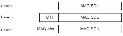
< 25.321 - Figure 9.2.1.2-1 : MAC PDU formats for BCCH >
Even though PCCH path does not have any MAC header in this process and MAC layer still do something for this channel. It is TFC (Transport format Combination) Selection. MAC-c/sh select a proper TFCI and pass it to transport layer and then the transport layer encode PCH, FACH data into PHY layer format.
Next Path is RACH to CCCH path (Uplink) and CCCH to FACH path (downlink). RRC Connection Request is going through RACH to CCCH path and RRC Connection Setup is going through CCCH to FACH path. This path is dealing with the following MAC PDU structure. In CCCH to FACH path, MAC-c/sh adds TCTF to MAC SDU. In RACH to CCCH path, MAC-c/sh check TCTF value and remove it and then distribute the SDU accordingly to higher layer.

< 25.321 - Figure 9.2.1.4-1 : MAC PDU formats for CCCH mapped to RACH/FACH >
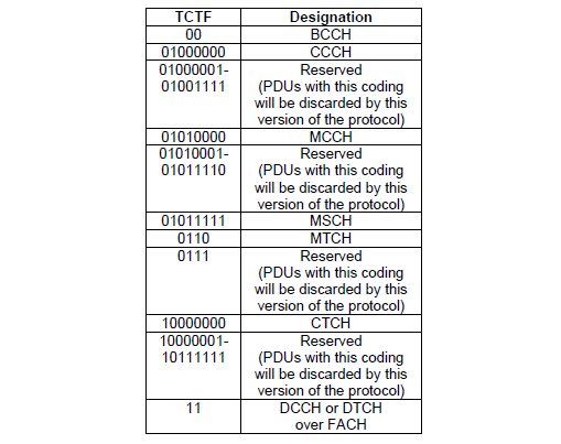
Meaning of TCTF value is summarized as in the following two tables.
< 25.321 - Table 9.2.1-2 : Coding of the Target Channel Type Field on FACH for FDD >
< 25.321 - Table 9.2.1-4 : Coding of the Target Channel Type Field on RACH for FDD >
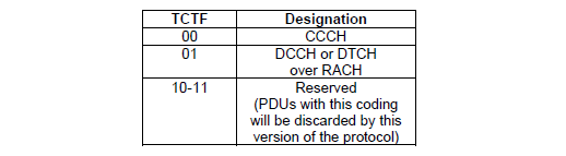
Look at the length of the codes in the FACH table before you decode a FACH PDU by hand. The TCTF on FACH for FDD is 2, 4 or 8 bits long. BCCH and DCCH or DTCH use 2 bits, MTCH uses 4 bits, and CCCH, CTCH, MCCH and MSCH use 8 bits. So the receiver reads the first bits first, and their value tells it how many TCTF bits follow. On RACH for FDD the TCTF is always 2 bits.
The same logical channel can also get a different code on each transport channel. CCCH is 00 on RACH but 01000000 on FACH. The last row of each table, DCCH or DTCH, is the path where MAC-c/sh hands the PDU over to MAC-d. The MAC-d page covers the UE-Id and C/T fields that follow the TCTF on that path.
PCCH on PCH has no MAC header : MAC-c/sh only selects the transport format combination for the PCH.BCCH in MAC-c/sh/m goes on FACH : it carries a TCTF of 00. BCCH on BCH has no MAC header, and MAC-b handles it.CCCH always has a TCTF on RACH and FACH : the value is 00 on RACH and 01000000 on FACH.The TCTF length depends on its first bits : 2, 4 or 8 bits on FDD FACH, and always 2 bits on FDD RACH.
Overview on MAC-c/sh/m in UE
Following is MAC-c/sh/m for UE side, but analysis logic and most of the detailed information is same as in UTRAN. The only thing you have to be careful about is direction of the path. For example, in this case, PCCH path is from the bottom (PCH) to UP (PCCH). CCCH path is also 'FACH to CCCH' or 'CCCH to RACH' which is opposite direction of UTRAN case.
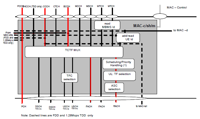
< 25.321 - Figure 4.2.3.1-1 : UE side MAC architecture / MAC-c/sh/m details >
Compare 25.321 Figure 4.2.3.1-1 with Figure 4.2.4.1-1 above, and you'll find a group of blocks on the RACH path that the UTRAN side does not have. They are there because the UE, not the network, starts a RACH transmission. The UE side also has blocks for MBMS reception on FACH.
add/read UE Id : adds the UE Id to DCCH or DTCH data sent on RACH, which is always the C-RNTI. On FACH, it reads the UE Id to find the data meant for this UE.read MBMS Id : reads the 4 bit MBMS-Id in the MAC header of MTCH, which identifies the MBMS service.Scheduling/Priority Handling : sends the data it receives from MAC-d on RACH in the order of the logical channel priorities.UL: TF selection and ASC selection : pick the transport format and the Access Service Class for each RACH transmission. The next section covers the ASC.Dashed lines : the note under the figure says they are FDD and 1.28 Mcps TDD only. They connect MAC-c/sh/m to MAC-ehs on the left and to MAC-is/i on the right, for common channels carried on HS-DSCH and E-DCH.
The TCTF MUX block does the same job as on the UTRAN side, in the opposite direction. It inserts the TCTF on uplink channels, and it detects and removes the TCTF on downlink channels.
The UE side reverses every path : PCH to PCCH, FACH to BCCH, FACH to CCCH and CCCH to RACH.The RACH blocks are UE side only : UE Id insertion, TF selection and ASC selection have no uplink counterpart in the UTRAN figure.RACH always uses the C-RNTI : 25.321 never uses the U-RNTI in the uplink.
How does MAC-c/sh/m control a RACH transmission ?
The UE figure above has an ASC selection block on the RACH path, and the UTRAN figure has none. The UE starts every RACH transmission on its own, so the UE MAC has to decide when it may try. This section follows that decision from the ASC to the AICH response.
Let's start with the ASC. In FDD, the PRACH access slots and preamble signatures can be split between up to 8 Access Service Classes. Each ASC i has a PRACH partition and a persistence value Pi, which is a transmission probability. ASC 0 has the highest priority, and it is used for an Emergency Call. RRC derives these parameters from system information and gives them to MAC with the CMAC-CONFIG-REQ primitive.
MAC then picks the ASC for each transmission. For an RRC Connection Request, RRC decides the ASC from the access class of the UE. In the other cases, MAC uses the MAC Logical channel Priority, or MLP, of the logical channels in the TB set. Each logical channel gets an MLP from 1 to 8 at radio bearer setup. MAC selects ASC = min(NumASC, MLP). When the TBs have different MLPs, MAC uses the highest priority, which is the lowest MLP value.
Next comes the persistence test. In each TTI, the UE tests against Pi. If the test fails, the UE tries again in the next TTI. If it passes, MAC asks L1 to start a preamble ramping cycle. The power of those preambles is on the PRACH Power page. The AICH answer decides the next step, as Figure 1 shows.
Figure 1. RACH transmission control in the UE MAC, summarised from 25.321 clause 11.2.2. Every outcome except ACK and failure leads back to a new persistence test, so Pi is checked again before every ramping cycle.
ACK on AICH : L1 reports "ready for data transmission", and the UE sends the PRACH message part. MAC then reports success to the higher layer.NACK on AICH : MAC starts the back-off timer TBO1. Its length is NBO1 intervals of 10 ms, drawn at random between NBO1min and NBO1max. A new persistence test follows when it expires.No AICH response : L1 has sent Preamble_Retrans_Max preambles without an answer. MAC runs a new persistence test in the next TTI, and the timer T2 keeps two tests at least 10 ms apart.More than Mmax ramping cycles : MAC reports a RACH failure. For CCCH it reports to RRC with CMAC-STATUS-Ind. For a logical channel on AM or UM RLC, it reports to RLC with MAC-STATUS-Ind.
RRC can also change these parameters at any time. Before each persistence test, MAC checks for a new CMAC-CONFIG-REQ and applies the latest set.
The persistence test runs before every ramping cycle : a low Pi spreads the access attempts of many UEs over time.RRC sets the ASC only for RRC Connection Request : in the other cases, the MLP of the logical channel decides it.A NACK adds a random wait : the UE waits TBO1 before the next persistence test. With no answer at all, the next test comes in the next TTI.
Reference
[1] 3GPP TS 25.321 v19.0.0 - clause 4.2.3.1 and 4.2.4.1, the MAC-c/sh/m entity, clause 9.2.1, the MAC header parameters, and clause 11.2, RACH transmission control