Channel Mapping : MAC-e/es
< Overview on MAC-e/es/i/is in UTRAN : HSUPA>
This is about HSUPA processing on UTRAN side. This process is so complicated and multiple modules get involved in this process. I strongly recommend you to revisit < Overview on MAC Layer in UTRAN >, go through Figure 4.2.4.1 and get familiar to HSUPA path as much as possible.
You would see the two blocks in figure 4.2.4.1. MAC-e/i at the bottom left part and MAC-es/is at top right side. HSUPA data goes through MAC-e/i first and then go to MAC-es/is.
As you will see from the following figures, MAC-e is more focused on L1 specific process like HARQ and Grant/ACK-NACK transmission. These processes requires a lot of real time processing power, so MAC-e is located in Node B.
On the contrary MAC-es is doing reordering and disassemble the MAC-e PDUs into multiple MAC-d PDU which does not require such a tight real time process. So this module is located in RNC.
The first question is "The data goes through MAC-e and MAC-i simultaneously ?" and "The data goes through MAC-es and MAC-is simultaneously ?".
The answer is NO. The HSUPA data goes through only one of the path. It has only two of the combination as follows :
i) MAC-e ---> MAC-es
ii) MAC-i ---> MAC-is
So you have to study MAC-e/MAC-es path and MAC-i/MAC-is path separately.
Then the next question is how UE can determine which path to follow ? This decision comes from the higher layer signaling message.
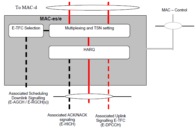
I think I have to update this sections for quite often since there are many details I have to revisit. For now, I will try to create a big picture. (When you read this figure, you should be careful about the direction. For the path marked in Black lines, you have to follow from the bottom to the top and for the path marked in red, you should follow from top to the bottom).
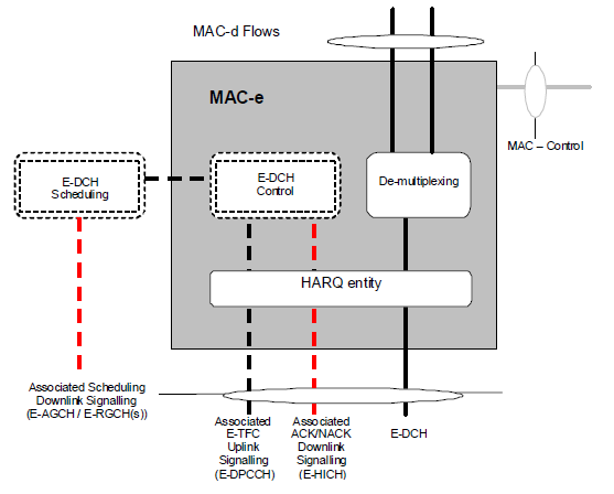
< 25.321 - Figure 4.2.4.5-1a : UTRAN side MAC architecture / MAC-e details(FDD) >
Following is the structure of MAC-es. One thing you would notice is that it has many blocks for Reordering. Why do you think we need this kind of reordering ? The answer would be that there are possibility that multiple PDUs from MAC-e may arrive out of sequence ? Then the question is How come those PDUs can arrive out of sequence. It is mainly because the HARQ process in MAC-e. Since multiple HARQ processes can run in paralell, we cannot guarantee that all those data stream coming out of the HARQ process arrive at MAC-es in sequence. So we need some mechanism to realign these incoming PDUs into a proper sequence before passing them to MAC-d. This is the role of Reordering block.
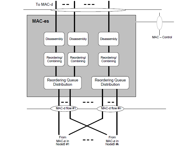
< 25.321 - Figure 4.2.4.4-1 : UTRAN side MAC architecture / MAC-es details(SHO case, FDD) >
Following is MAC-i/MAC-is path. For now, just go through the diagram and try to make your own story.
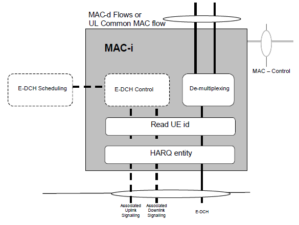
< 25.321 - Figure 4.2.4.8-1 : UTRAN side MAC architecture / MAC-i details(FDD) >
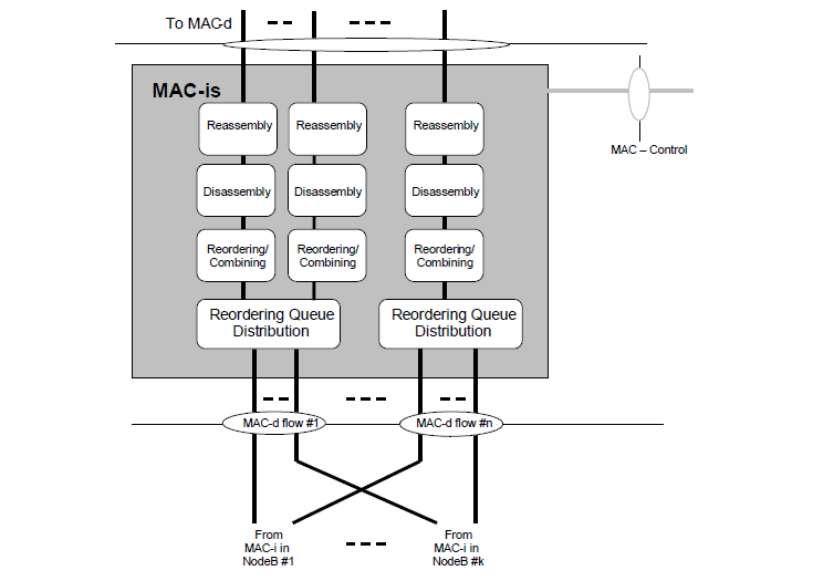
< 25.321 - Figure 4.2.4.7-1 : UTRAN side MAC architecture / MAC-is details for DCCH/DTCH transmission(SHO case, FDD only) >
It would be more helpful if have the MAC PDU structure, but will come in the following section < Overview on MAC-e/es in UE : HSUPA >. I normally put the PDU structure on transmission side.
< Overview on MAC-e/es and MAC-i/is in UE : HSUPA >
UE side HSUPA block is a little bit simpler than UTRAN side since MAC-e/es are combined in one module.
For now just try to follow all the possible paths in the following figures.
(When you read this figure, you should be careful about the direction. For the path marked in Black lines, you have to follow from the bottom to the top and for the path marked in red, you should follow from top to the bottom).
For every transmission (TTI), UE MAC-es/s determines the data rate by following criteria
i) Current Serving Grant
ii) Amount of Data waiting to be transmitted
iii) Minimum Allowed Spreading Factor (determined by higher layer signaling)
This sublayer can use multiple HARQs in paralelle and the maximum number of HARQ differs depending on TTI.
i) For 10 ms TTI - 4 HARQs
ii) For 2 ms TTI - 8 HARQs
The HARQ process that transmits in a particular frame is determined from the current SFN (this is unlike HSDPA where each HARQ process transmits in a round-robin fashion).
UE can use chase combining (transmission of the exact same bits again) or incremental redundancy (transmission of a different set of bits) for HARQ retransmission and the RRC layer message determines which method UE has to use.
< 25.321 - Figure 4.2.3.4.1a : UE side MAC architecture / MAC-e/es details(FDD) >
You will get a little bit detailed understanding if you look into the PDU structure as follows.
First PDU is MAC-es PDU. From this structure, you would notice that the main role of MAC-es is to take in multiple MAC-d PDUs and combine them into a single MAC-es PDU.
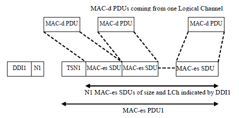
< 25.321 - Figure 9.1.5.1 : MAC-es PDU >
Meaning of the parameters in the MAC-es PDU is described in the table below.
|
Field |
Field Name |
Bits |
Description |
|
TSN |
Transmission Sequence Number |
6 |
The TSN field provides the transmission sequence number for the MAC-es PDU. This information is used for reordering purposes to support in-sequence delivery to higher layers. |
| DDI |
Data description indicator |
6 |
The DDI field identifies the logical channel, MAC-d flow and size of the MAC-d PDUs concatenated into the associated MAC-es PDU. The mapping between the DDI values and the logical channel ID, MAC-d flow and PDU size is provided by higher layers |
| N |
Number of MAC-d PDUs |
6 |
The number of consecutive MAC-d PDUs corresponding to the same DDI value. |
Now let's look into MAC-e PDU. From this, you would notice that MAC-e takes in multiple MAC-es PDUs and combine them into a single/big MAC-e PDU. Another thing you should notice is.. MAC-e collect all DDI/N part and connect all of them at the beginning of MAC-e PDU and put all the payload part of MAC-es PDU next to the DDI/N portion.
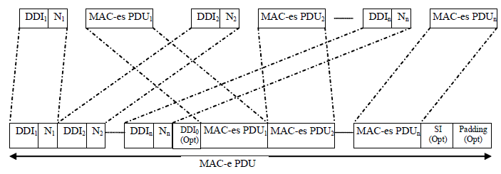
< 25.321 - Figure 9.1.5.2a : MAC-e PDU >
If you want to be able to decode MAC-e PDU completely upto the level of MAC-d SDU level, following illustration would give you better understanding (This come from the combination of Figure 9.1.5.2a, Figure 9.1.5.1 , Figure 9.2.1.1.1)
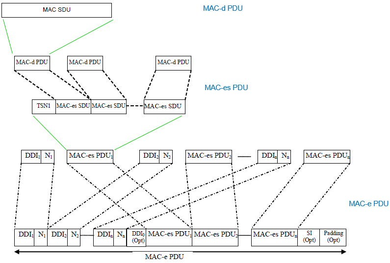
NOTE : If you tried to decode MAC-e PDU by hands, you would come across an important question. It is, "How do I know the end of MAC-e Header ?".. in other words "How can I know which one is the last DDI ?"
You can find the answer in 25.321-9.2.4.2 MAC-e header parameters, but the short answer is that if you hit [111111] in a DDI field, it means the previous DDI is the last DDI. [111111] is the indicator of end-of-the-header.