A UMTS radio frame can carry several transport channels at once, and each of them may change its data rate every TTI. The receiver has to know which rates were used before it can decode anything. TFI and TFCI carry this information. TFI is the label for one transport channel between MAC and L1. TFCI is the label for the whole CCTrCH, and it goes over the air.
- What are TFI and TFCI ?
- How does a TFCI value point to a transport format combination ?
- How is the TFCI sent on the air ?
- Reference
What are TFI and TFCI ?
TFI stands for Transport Format Indicator TFCI stands for Transport Format Combination Indicator. As you see in the following diagram each transport channel's Transport Block Set has one TFI attached to it. In physical layer, multiple transport blocks are combined into a large 'transmission frame'. This combined transmission frame is called Coded Composite Transport Channel (CCTrCh). Each CCTrCH frame gets its own indicator which is called TFCI.
The diagram below follows one TTI from the transmitter on the left to the receiver on the right. Above the dashed line is MAC, which the diagram calls the higher layer. Below it is the physical layer. Two transport channels each deliver two transport blocks and one TFI. On the receiving side the transport blocks come back up with an error indication, which is the CRC result.
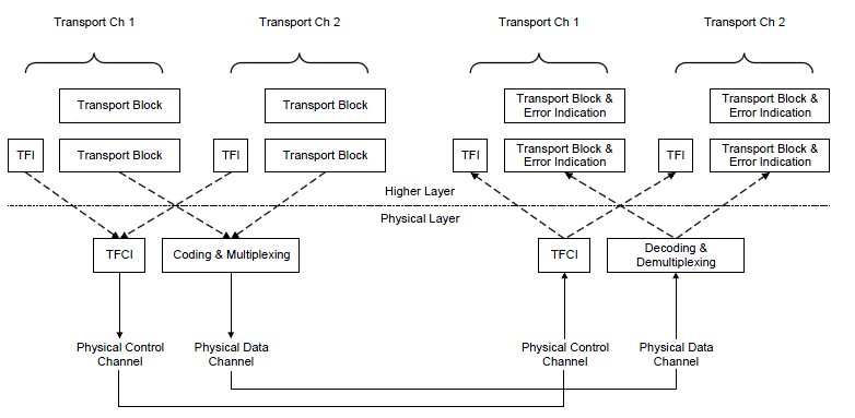
The TFIs of all transport channels become one TFCI on the physical control channel, and the receiver turns that TFCI back into one TFI per transport channel.
TFI crosses the MAC to L1 boundary : There is one TFI per transport channel per TTI, whatever the number of transport blocks.TFCI is built in the physical layer : L1 combines the TFIs of Transport Ch 1 and Transport Ch 2 into one TFCI and sends it on the Physical Control Channel, the DPCCH.Data and TFCI travel on different channels : Coding and multiplexing put the transport blocks on the Physical Data Channel, the DPDCH, in the same radio frame.The receiver reads the TFCI first : Only after it knows the TFCI can it decode, demultiplex and hand each transport block to the right transport channel.
TFI plays roles as follows.
- The TFI is a label for a specific transport format within a transport format set.
- It is used in the inter-layer communication between MAC and L1 each time a transport block set is exchanged between the two layers on a transport channel.
- When the DSCH is associated with a DCH, the TFI of the DSCH also indicates the physical channel (i.e. the channelisation code) of the DSCH that has to be listened by a UE
TFCI plays roles as follows.
- This is a representation of the current Transport Format Combination.
- The TFCI is used in order to inform the receiving side of the currently valid Transport Format Combination, and hence how to decode, de-multiplex and deliver the received data on the appropriate Transport Channels.
- There is a one-to-one correspondence between a certain value of the TFCI and a certain Transport Format Combination.
- MAC indicates the TFI to Layer 1 at each delivery of Transport Block Sets on each Transport Channel. Layer 1 then builds the TFCI from the TFIs of all parallel transport channels of the UE, processes the Transport Blocks appropriately and appends the TFCI to the physical control signalling.
- Through the detection of the TFCI the receiving side is able to identify the Transport Format Combination.
3GPP TS 25.302 adds two limits to this model. First, the TFCI is not used for the HS-DSCH and the E-DCH. Those channels signal their formats differently, with the TFRI on the HS-SCCH and the E-TFCI on the E-DPCCH. Second, in FDD the TFCI may be left out when the set of combinations is small. The receiver then finds the combination by blind detection. The DSCH that the TFI list mentions is an early shared downlink channel. In practice, HSDPA and its HS-DSCH took over that role.
TFI is internal, TFCI is on the air : You never see a TFI in an air interface log, but you see the TFCI in every DPCCH slot that carries one.One TFCI covers all DCHs : In the uplink there is only one TFCI for all DCHs of one CCTrCH.No TFCI for HSPA : HS-DSCH and E-DCH do not use TFCI.
How does a TFCI value point to a transport format combination ?
A TFCI is only a number, so both sides need the same table to read it. RRC sets up that table in advance, and the TFCI then just picks one row. Let's build the table from the bottom up, the way 25.302 defines the terms.
A Transport Format, TF, is one allowed shape of the data on one transport channel. Its dynamic part is the transport block size and the transport block set size. Its semi-static part is the TTI, the coding type and the static rate matching parameter. All TFs of one transport channel form its Transport Format Set, TFS, and the TFI is the index of a TF within that set. A Transport Format Combination, TFC, takes one TF from each transport channel of the CCTrCH. The Transport Format Combination Set, TFCS, is the list of TFCs that the network allows. It does not have to contain every possible combination. By leaving out the combinations where all channels run at high rate, the network limits the total bit rate of the CCTrCH.
RRC does not send each TFC as a list of TFIs. It sends one number per TFC, the Calculated Transport Format Combination, CTFC, from 25.331. Suppose there are I transport channels and TrCHi has Li transport formats, so TFIi runs from 0 to Li - 1. With L0 = 1, define Pi as the product of L0 to Li-1. Then CTFC is the sum of TFIi x Pi over all transport channels. This is a mixed radix number, so each TFC has its own CTFC value. TrCH1 is the transport channel with the lowest transport channel identity, and so on.
Here is a small example. TrCH1 has 3 TFs, and TrCH2 and TrCH3 have 2 TFs each. So P1 = 1, P2 = 3 and P3 = 6, and the CTFC runs from 0 to 11. Suppose the network allows only four of the twelve combinations. The table below shows them in the order the network signals them.
Position in the list = TFCI in FDD |
TFI1 |
TFI2 |
TFI3 |
CTFC |
0 |
0 |
0 |
0 |
0 |
1 |
1 |
0 |
1 |
1 + 6 = 7 |
2 |
2 |
1 |
0 |
2 + 3 = 5 |
3 |
2 |
1 |
1 |
2 + 3 + 6 = 11 |
Note that the TFCI is not the CTFC. The TFCI is the position of the CTFC in the signalled list. For a complete reconfiguration in FDD, the first CTFC in the list is TFCI 0, the second is TFCI 1, and so on. In TDD the count starts at 1, because TFCI 0 is reserved for the physical layer. So in the example, a DPCCH that carries TFCI 2 tells the receiver that TrCH1 uses TFI 2, TrCH2 uses TFI 1 and TrCH3 uses TFI 0.
The IEs below carry the list in RRC. The ctfcSize choice lets the network use as few bits per CTFC as the largest value needs. Each entry can also carry power offset information, which gives the uplink gain factors for that TFC. The addition, removal and replacement branches are the incremental reconfiguration of 25.302, which keeps some TFCI values unchanged.
Following is based on
TFCS ::=							CHOICE {
	normalTFCI-Signalling				ExplicitTFCS-Configuration,
	-- dummy is not used in this version of specification, it should
	-- not be sent and if received the UE behaviour is not specified.
	dummy								SplitTFCI-Signalling
}

ExplicitTFCS-Configuration ::=		CHOICE {
	complete							TFCS-ReconfAdd,
	addition							TFCS-ReconfAdd,
	removal								TFCS-RemovalList,
	replacement							SEQUENCE {
		tfcsRemoval							TFCS-RemovalList,
		tfcsAdd								TFCS-ReconfAdd
	}
}

TFCS-ReconfAdd ::=					SEQUENCE{
	ctfcSize							CHOICE{
		ctfc2Bit							SEQUENCE (SIZE (1..maxTFC)) OF SEQUENCE {
			ctfc2								INTEGER (0..3),
			powerOffsetInformation				PowerOffsetInformation			OPTIONAL
		},
		ctfc4Bit							SEQUENCE (SIZE (1..maxTFC)) OF SEQUENCE {
			ctfc4 								INTEGER (0..15),
			powerOffsetInformation				PowerOffsetInformation			OPTIONAL
		},
		ctfc6Bit							SEQUENCE (SIZE (1..maxTFC)) OF SEQUENCE {
			ctfc6								INTEGER (0..63),
			powerOffsetInformation				PowerOffsetInformation			OPTIONAL
		},
		ctfc8Bit							SEQUENCE (SIZE (1..maxTFC)) OF SEQUENCE {
			ctfc8								INTEGER (0..255),
			powerOffsetInformation				PowerOffsetInformation			OPTIONAL
		},
		ctfc12Bit							SEQUENCE (SIZE(1..maxTFC)) OF SEQUENCE {
			ctfc12								INTEGER (0..4095),
 			powerOffsetInformation				PowerOffsetInformation			OPTIONAL
		},
		ctfc16Bit							SEQUENCE (SIZE (1..maxTFC)) OF SEQUENCE {
			ctfc16								INTEGER(0..65535),
			powerOffsetInformation				PowerOffsetInformation			OPTIONAL
		},
		ctfc24Bit							SEQUENCE (SIZE (1..maxTFC)) OF SEQUENCE {
			ctfc24								INTEGER(0..16777215),
			powerOffsetInformation				PowerOffsetInformation			OPTIONAL
		}
	}
}

TFCS-Removal ::=					SEQUENCE {
	tfci								INTEGER (0..1023)
}

TFCS-RemovalList ::=				SEQUENCE (SIZE (1..maxTFC)) OF
										TFCS-Removal
TFCI is an index, CTFC is the content : Changing the order of the CTFC list changes the meaning of every TFCI value.The TFCS is a subset : The network lists only the combinations it wants to allow, and that is how it caps the total rate of the CCTrCH.TrCH order follows the transport channel identity : Put the TrCHs in the wrong order and every CTFC decodes to the wrong TFIs.
How is the TFCI sent on the air ?
The TFCI must reach the receiver even when the data does not decode, because without it nothing can be decoded at all. So 25.212 protects it with a strong block code, and it spreads the coded bits over the whole radio frame.
The TFCI has at most 10 information bits, a0 to a9, where a0 is the LSB. A shorter TFCI is padded with zeros in the most significant bits. The 10 bits are encoded with a (32, 10) sub-code of the second order Reed-Muller code, which gives a 32 bit code word. The code word bits are then mapped straight to the slots of the radio frame. In the uplink, and in the downlink with SF 128 or more, only 30 bits are sent, so b30 and b31 are not transmitted. With 15 slots per frame, that is 2 TFCI bits per slot. In the downlink with SF below 128, the code word is repeated to 120 bits, 8 bits per slot. In compressed mode 25.212 uses a different mapping, because some slots of the frame are not sent.
When the TFCI is not sent, the UE uses blind transport format detection. 25.212 sets strict limits for this case. For example, there are at most 64 TFCs, at most 600 CCTrCH bits per radio frame and at most 3 explicitly detectable TrCHs. All of those TrCHs use convolutional coding with a CRC. So blind detection suits small, low rate configurations, and the TFCI is the normal case.
10 bits give up to 1024 TFCs : This matches maxTFC = 1024 and the tfci range 0..1023 in the RRC ASN.1.One TFCI per radio frame : The receiver needs the full 10 ms frame before it can decode the TFCI, and only then the data of that frame.Blind detection saves the TFCI field : It works only inside the limits of 25.212 4.3.1, so the network has to plan the TFCS for it.
Reference
- 3GPP TS 25.302 v19.0.0 : Services provided by the physical layer
- 3GPP TS 25.212 v19.0.0 : Multiplexing and channel coding (FDD)
- 3GPP TS 25.331 v19.0.1 : Radio Resource Control (RRC); Protocol specification