|
IP/Network |
||
|
OSI 7 Layer
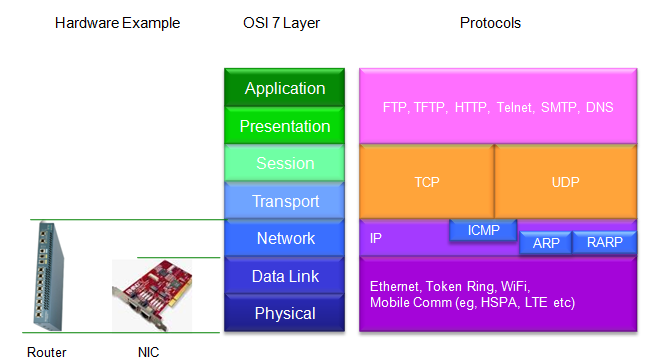
Anybody who got any kind of trainings on any type of communication system may have learned about OSI 7 layer (OSI stands for Open System Interconnection). It has become the frame of idea on almost any form of communication system. It may look simple and may sound simple, but I feel I find new aspect of this model everytime I see it even after more than 10 years since I first learned about it. I would not put much of my own comments here. My recommendation is "Just look at the diagram and make any form of your own comment". If you ask 100 persons to draw this model, they would add a little bit of different variations on their own. Just google 'OSI 7 layer' on Google image. You would see a lot of diagram. You will find a common framework, but you will notice none of them are exactly same and each of them has their own images. Following is one form of illustration that I like and I also put a little variation from my own idea.
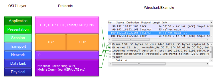
What's happening when a data goes through each layer ? Each layer has it's own process and the process produce its own output and pass it to another layer. It is not easy to get the detailed description of those 'process', but you would easily get the 'output' of those processes just by taking a sample of wireshark log. Following is one example log that I captured for sending one character 'e' using 'telnet'. (Click here if you want to get the sample log shown here). There is one part that cannot be captured by wireshark is PHY(Physical Layer) data. For the very raw physical layer data, you would need to special equipment (e.g, oscilloscope, Logic Analyzer, Signal Analyzer etc). There is also a part that can be captured but requires more analytic skill is 'Session' layer. Just pick one line and Try to go from the bottom to the top (in this case, Telnet -> TCP -> IPv4 -> Ethernet II -> Frame) and want kind of information gets added at each layer and what kind of data structure is used at each layer (If you want to further details, try to google 'Ethernet frame structure', IP header, TCP header, UDP header etc)
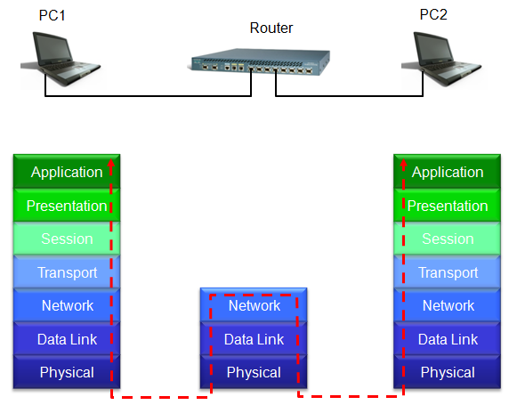
When you have any certain physical entities forming a communication system, try to express those physical entities in the form of OSI 7 layer model. If you pick around 5 different network configuration and try this conversion, it would be better than reading 5 different thick books. One example of this practice can be illustrated as follows. And imagine you just sent 'ONE BIT' from one place to another place and try to figure out what would happen to the ONE BIT at each of the layer and what would happen when the ONE BIT pass the boundary of each of the layers.
|
||