LTN(Low Throughput Network)
LTN, Low Throughput Network, is the ETSI name for a wide area network built for devices that send a few bytes now and then. This page maps the LTN network elements onto the LTE elements you already know. Then it shows how an operator can combine an LTN with an existing cellular network, and why that combination is the practical way to reach wide coverage.
Overall Network Architecture
LTN Network Architecture is also very similar to other celluar network (e.g, LTE, WCDMA etc). They just use a little bit different names for each network components.
Assuming that most of the readers are more familiar with cellular network (e.g, LTE, WCDMA), I would try to put some comments on this network comparing LTE network.
In LTE/WCDMA, you would first have a user device to be camped on to a network. We call this user device as 'UE' or 'Mobile Phone'. In LTN, the component corresponding to UE is LEP (LTN End Point).
And then, in LTE/WCDMA, the UE first communicate to the Access Network called 'eNB' or 'BTS'. The component corresponding to eNT/BTS in LTN is called LAP (LTN Access Point).
Then in LTE/WCDMA, there is some intermediate components between Access Network and Corenetwork like MME, SGW/PGW, or SGSN/GGSN, but I don't see any intermediate compoments like this in LTN. In this sense, we can say LTN Architecture is simpler than the wide scale cellular network (LTE/WCDMA Network).
In backend, there usually be various kinds of Authentication Center, Application Servers in Cellular network. Similary, in LTN there are various Servers like LTN Server, CRA, OSS/BSS. LTN Server is working as data traffic center and CRA can be a kind of Authentication Center and OSS/BSS can be a policy handling center.
Overall network architecture is illustrated as follows. This is based on ETSI GS LTN 003 Figure 1.
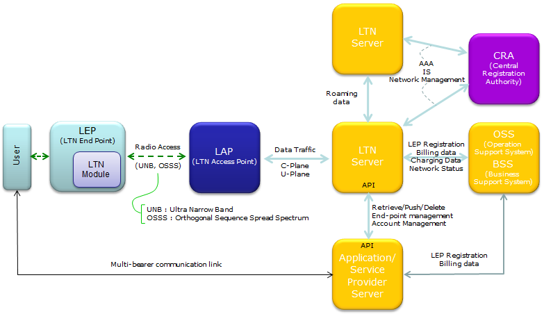
Let's read the drawing from left to right. Each arrow carries a label for what flows over it, and those labels tell you what each element is responsible for.
The LEP plays the role of the UE : The User talks to the LEP, and the LEP carries an LTN Module. The LEP is the only element on the device side of the radio link.LEP to LAP is the only radio link : The drawing labels it Radio Access and names two radio techniques for it. They are UNB, Ultra Narrow Band, and OSSS, Orthogonal Sequence Spread Spectrum.LAP to LTN Server carries all the traffic : The label is Data Traffic, and it covers both the C-Plane and the U-Plane. In LTE, the same traffic would split after the eNB, with control going to the MME and user data going to the SGW/PGW.Two LTN Servers exchange Roaming data : The upper LTN Server stands for another LTN network. The link between the two servers carries the data of a roaming LEP.The CRA handles AAA : The CRA, Central Registration Authority, connects to both LTN Servers. Its labels are AAA, IS and Network Management, so it plays a role close to the HSS or the authentication center of a cellular network.The OSS/BSS handles registration and money : LEP Registration, Billing data, Charging Data and Network Status flow between the LTN Server and the OSS/BSS. The OSS/BSS also sends LEP Registration and Billing data to the Application/Service Provider Server.Applications use an API on the LTN Server : Both ends of this link carry an API. Over it, the application can Retrieve, Push or Delete data, and it handles End-point management and Account Management.The User also has a direct path : A Multi-bearer communication link connects the User with the Application/Service Provider Server outside the LTN path.
The drawing also shows why the architecture can stay this flat. An LEP typically sends short and infrequent messages, and it does not keep a data session that must follow it from one LAP to another. So the network needs no mobility anchor like the SGW and no separate control node like the MME. One LTN Server does the jobs that those nodes share in LTE.
LEP, LAP and LTN Server map onto UE, eNB and core network : The LTN Server takes the role that the MME, SGW and PGW share in LTE.The CRA and the OSS/BSS sit beside the LTN Server : The CRA handles AAA and registration, and the OSS/BSS handles billing, charging and network status.Applications reach the devices only through the LTN Server : They use its API, and they never talk to a LAP directly.
LTN Interplay with Cellular Network
It would be possible to cover all the area globally (or nation wide) with the network architecture we described in previous section ? Let's think about it the way an operator would. The radio can reach far, but national coverage still needs a large number of LAPs, sites and backhaul links. Someone has to build, run and pay for all of them.
I think it is possible technically, but questions is 'how about in business point of view ?'. As you know, deplaying any kind of wide scale network (Nationwide or Global) get various kinds of business factors.
So in more practical approach would be to deploy/implement LTN in a restricted/local area and connect it to an existing/wide scale cellular network to get all of these LTN globally connected to each other.
Another reason for coorperation of LTN and Cellular network is (according to ETSI GS LTN 003) : LTN could coorperate with cellular networks to address use cases where redundancy, complimentary or alternative connectivity is needed.
One of the possible configuration of combining LTN and Celluar Network is suggested as follows (from ETSI GS LTN 001 Figure 3).
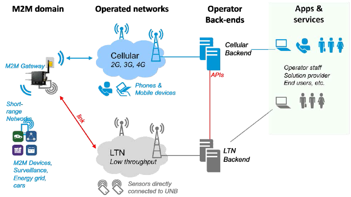
The drawing has four columns. Read them from left to right, because the data flows in that direction, from the devices to the applications.
M2M domain : An M2M Gateway collects data from Short-range Networks, which serve M2M Devices, Surveillance, Energy grid and cars. The gateway has one link to the cellular network and a second link to the LTN.Operated networks : The Cellular network, 2G, 3G and 4G, also serves Phones & Mobile devices. The LTN, Low throughput, also serves Sensors directly connected to UNB.Operator Back-ends : Each network has its own backend, the Cellular Backend and the LTN Backend. The two backends are connected by APIs, drawn as the red line between them.Apps & services : Operator staff, Solution provider and End users reach the services through both backends.
Notice the red link between the M2M Gateway and the LTN. It is what makes the redundancy use case possible. If the cellular path to the gateway fails, the gateway can still send its most important data over the LTN. The APIs between the two backends then let the applications see one service rather than two separate networks.
Deploy LTN locally and connect it globally : A local LTN plus an existing cellular network gives wide reach without a nationwide LTN build.The M2M Gateway is the meeting point of the two networks : It holds both a cellular link and an LTN link, so one path can serve as a backup for the other.Integration happens at the back-end : The Cellular Backend and the LTN Backend exchange data through APIs, not over the radio.