A sniffer is a tool used to capture and analyze the wireless traffic exchanged between a mobile device (UE - User Equipment) and the base station (eNB - evolved NodeB or gNB - next generation NodeB). Essentially, it's like a "network eavesdropper" that allows you to see the raw data being transmitted over the air.
- Key Features of Sniffers
- Implementation Example
Key Features of Sniffers
There are several key features of sniffers in the context of LTE/NR networks, but it's important to understand that not every sniffer supports all of them. The specific features and the degree to which they are supported depend largely on the intended purpose and use case of a particular sniffer. Some sniffers might be designed for a simple task, such as sniffing only a few physical channels to monitor basic network activity. Others are designed with full-fledged functionality, capturing all physical channels (both uplink and downlink) and decoding those channels to reconstruct complete packets and messages across the entire protocol stack. This range of capabilities allows for diverse applications, from basic signal monitoring to in-depth protocol analysis and security assessments.
Followings are some of the features of Sniffers. I think the item 'Passive Monitoring' would apply to all sniffers but other features may or may not be supported depending the specific sniffers.
Passive Monitoring : Sniffers operate discreetly, capturing data "over the air" without actively transmitting any signals. This non-intrusive approach allows them to observe network traffic without interfering with its normal operation or being detected by the network itself or the users being monitored. This is crucial for real-world analysis and security assessments, as it provides an accurate picture of the network's behavior without any artificial influences.Protocol Analysis : LTE/NR sniffers are designed to understand the complex structure of cellular communications. They go beyond simply capturing raw data by decoding and interpreting the various protocol layers used in these technologies. This includes Layer 1 (the physical layer where signals are modulated and transmitted), Layer 2 (which handles tasks like media access control, radio link control, and packet data convergence protocol), and Layer 3 (responsible for radio resource control). By dissecting these layers, sniffers can provide valuable insights into the network's operation, identify potential vulnerabilities, and analyze performance bottlenecks.Frequency Support : LTE/NR networks operate across a range of frequency bands globally. For a sniffer to be effective, it must be compatible with the specific frequencies deployed in the target network. This requires the sniffer's hardware to be capable of tuning to and receiving signals on those specific frequencies. Without the correct frequency support, the sniffer would be unable to capture any data at all.Demodulation and Decoding : LTE/NR utilize sophisticated modulation techniques to efficiently transmit data over the air. These techniques involve encoding information onto radio waves by varying their amplitude and phase. Sniffers must be equipped with demodulation capabilities to reverse this process, extracting the encoded information from the received signals. They need to handle various modulation schemes like QPSK, 16-QAM, 64-QAM (and even higher orders like 256-QAM for NR) to accurately recover the transmitted data. After demodulation, the sniffer further decodes the raw data to reconstruct the higher-layer protocol messages, making the captured information interpretable and analyzable.Bandwidth Support : LTE/NR networks can operate with different channel bandwidths, impacting the amount of data that can be transmitted at a given time. A sniffer must be able to accommodate this variability, handling bandwidths ranging from 1.4 MHz to 20 MHz in LTE and up to 400 MHz in NR. This ensures that the sniffer can capture and analyze data from networks with different configurations and capacity requirements.Multi-Cell Support : Modern LTE/NR networks often employ multiple cells and layers to enhance capacity and coverage. This includes techniques like Carrier Aggregation (CA) in LTE and the use of multiple gNB components in NR. An effective sniffer should be capable of capturing and analyzing data from multiple cells simultaneously, providing a comprehensive view of the network's performance and behavior in a multi-cell environment. This is essential for understanding complex interactions between cells and identifying potential issues related to handover, interference, and resource allocation.
Implementation Example : LTE Sniffer
The LTE Sniffer is an open-source tool designed to capture, decode, and analyze LTE traffic in both the uplink and downlink directions. Developed to overcome the limitations of existing tools, it leverages unencrypted control information within LTE signals to decode traffic. The tool supports researchers in analyzing LTE networks for security, performance optimization, and traffic analysis. It relies on the SRSRAN library for its downlink functionality and utilizes specialized hardware like the USRP X-series SDR for uplink operations.
Features/Capabilities
Followings are features and capabilities of LTE Sniffer. Even though it is provided as an open source (free), the overall capability is impressive especially for the fact that it can capture/decode both downlink and uplink (most of open source sniffer decode only downlink or uplink based on the major use case of the sniffer).
Dual-Direction Traffic Decoding: - Decodes downlink control and data channels (PDCCH, PDSCH).
- Decodes uplink control and data channels (PUCCH, PUSCH).
Open Source: - Fully open, enabling customization and integration into research projects.
Advanced Decoding Techniques: - Utilizes unencrypted Downlink Control Information (DCI) to decode data.
- Dynamically learns radio configurations and stores decoding parameters for subsequent packets.
Security API: Enables researchers to analyze LTE security vulnerabilities, including: - Identity Mapping (IMSI to RNTI).
- Permanent Identity Collection (IMSI tracking).
- UE Capability Profiling.
Data Export: - Stores decoded traffic as PCAP files, enabling further analysis using tools like Wireshark.
Performance: - Handles up to 256 users concurrently for uplink and downlink traffic.
How it works ?
The ultimate objective of the LTE Sniffer is to successfully decode both downlink and uplink data channels, specifically the Physical Downlink Shared Channel (PDSCH) and the Physical Uplink Shared Channel (PUSCH). These channels carry the actual user data, such as internet traffic or voice packets, making them crucial for understanding the network's operation and analyzing communication between the User Equipment (UE) and the base station.
Decoding these channels, however, relies heavily on accessing the Downlink Control Information (DCI), which serves as the blueprint for how the data in these channels is structured and transmitted. DCI provides essential details such as resource block allocations, modulation and coding schemes, and the instructions needed for the UE to decode downlink data or transmit uplink data. Despite LTE's overall security design, the DCI itself is transmitted in the Downlink Control Channel (PDCCH) without encryption. This lack of encryption in the DCI is critical for the sniffer's operation, as it allows the tool to intercept and interpret the control information necessary for decoding both downlink and uplink data channels. By leveraging this unencrypted control data, the LTE Sniffer can effectively demodulate and decode the user data that flows through these key channels
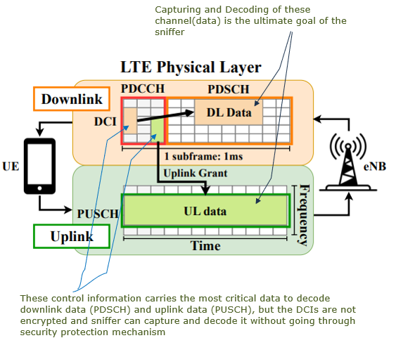
Image Source : LTESniffer: An Open-source LTE Downlink/Uplink Eavesdropper
Following shows at which point the LTE sniffer get involved. The LTE Sniffer works by decoding DCI sent over the PDCCH, which provides instructions for locating and decoding user data on the PDSCH (downlink) and PUSCH (uplink). The RNTI (Radio Network Temporary Identifier) plays a crucial role in this process because it acts as a unique identifier for each user within a cell. Since multiple UEs communicate with the base station simultaneously, the RNTI allows the sniffer to distinguish which DCI belongs to which UE.
In the downlink, the sniffer captures the DCI along with the associated RNTIs to identify user-specific data in the PDSCH. The DCI tells the sniffer where the data for a particular RNTI (and thus a particular user) is located. In the uplink, the sniffer uses uplink-specific DCI to determine how and where a user sends data on the PUSCH. By mapping the RNTI to the control information, the sniffer can track and decode uplink and downlink traffic for individual users accurately.
The RNTI is essential because, without it, the sniffer cannot associate the DCI instructions with the correct user data. By capturing the unencrypted DCI and linking it to the corresponding RNTI, the LTE Sniffer can reconstruct communication flows between UEs and the base station. This process allows it to decode traffic for multiple users within the cell efficiently, even as resource allocations dynamically change.
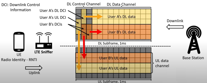
Image Source : LTESniffer: An Open-source LTE Downlink/Uplink Eavesdropper
This diagram provides a detailed view of the LTE Sniffer's workflow at signal processing level, illustrating the process of decoding both downlink (DL) and uplink (UL) LTE traffic. The workflow involves multiple stages, starting from signal processing and ending with the final decoding of data channels. Each stage plays a crucial role in handling the complexities of LTE communication, including synchronization, configuration extraction, and decoding.
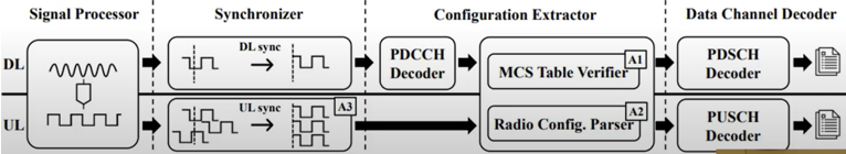
Image Source : LTESniffer: An Open-source LTE Downlink/Uplink Eavesdropper
Followings are break downs of this process step by step
-
At the beginning of the process, the Signal Processor captures LTE signals from the air interface for both downlink (DL) and uplink (UL).
-
These raw signals are passed to the Synchronizer, where the following steps occur:
-
DL sync (downlink synchronization).
-
UL sync (uplink synchronization).
-
Synchronization ensures that the sniffer aligns accurately with the LTE subframe timing, which is critical for correct signal interpretation.
-
Once synchronized, the signals move to the Configuration Extractor:
-
The sniffer extracts and decodes the PDCCH (Physical Downlink Control Channel).
-
The PDCCH contains DCI (Downlink Control Information), which provides instructions for locating and decoding data channels.
-
The MCS Table Verifier determines the correct Modulation and Coding Scheme (MCS) to decode data with the appropriate modulation settings.
-
The Radio Configuration Parser extracts dynamic radio parameters, including resource block allocations and channel settings, necessary for interpreting downlink and uplink traffic.
-
In the Data Channel Decoder phase:
-
For downlink, the sniffer uses the DCI from the PDCCH to decode the PDSCH (Physical Downlink Shared Channel), which carries user-specific data sent from the base station to the UE.
-
For uplink, the sniffer applies uplink radio configurations and decodes the PUSCH (Physical Uplink Shared Channel), which contains data sent from the UE to the base station.
-
The final output is the decoded downlink and uplink traffic, which can be further analyzed or stored for research purposes.
-
The process relies on:
-
Extracting DCI from the unencrypted control channel.
-
Synchronizing timing.
-
Adapting to dynamic radio configurations.
-
By following this workflow, the LTE Sniffer effectively reconstructs LTE communication and provides insights into both user-specific and network-level data exchanges.
Advantages Over Other Products
- Improved Capabilities:
- Unlike other sniffers like srsLTE's SCOPE, which only supports downlink, LTE Sniffer handles uplink traffic as well.
- Offers a higher decoding success rate compared to older versions of commercial sniffers.
- Cost-Effective:
- Open-source nature makes it accessible for researchers without high costs associated with commercial tools like WaveJudge.
- Customizable:
- Open-source code allows researchers to modify and extend functionality to meet specific needs.
- Research-Oriented:
- Designed with researchers in mind, providing APIs to explore LTE security issues like location tracking and fingerprinting.
Challenges(Problems) and Solutions
LTE traffic decoding involves several complexities due to the dynamic and partially encrypted nature of the LTE protocol. LTE Sniffer overcomes these challenges through innovative techniques, but the process is far from straightforward. Below is an in-depth explanation of the major challenges and their solutions
LTE dynamically adjusts the modulation and coding scheme (MCS) for each user based on channel conditions. The MCS determines how bits are modulated (e.g., QPSK, 16-QAM, 64-QAM) and encoded. The specific MCS information is transmitted in encrypted control messages(e.g, RRCConnectionReconfiguration), making it inaccessible to the sniffer.
- Why It's Hard:
- Without the MCS, the sniffer cannot correctly decode the data packets, as it won't know how to interpret the signal constellation.
- Solution in LTE Sniffer:
- Brute-Force Decoding: The sniffer attempts multiple possible MCS configurations to decode the first packet.
- Learning and Storing: Once the correct MCS is identified, it is stored in a database and reused for subsequent packets from the same UE. This reduces computational overhead for later packets.
LTE networks optimize radio parameters for each UE based on its channel quality (e.g., signal-to-noise ratio, interference). These configurations include:
- Resource Block (RB) allocation.
- Power control settings.
- Timing advance adjustments.
The base station continuously updates these configurations, and the sniffer must identify them in real time to decode packets correctly.
- Why It's Hard:
- Each UE's configuration is unique and changes frequently, requiring the sniffer to adapt dynamically.
- Solution in LTE Sniffer:
- Monitoring Radio Setup Procedures: The sniffer captures unencrypted downlink control information (DCI) during initial setup and reconfiguration phases.
- Configuration Database: Stores detected configurations for each UE, allowing the sniffer to adapt to changes efficiently.
- Continuous Updates: Monitors base station messages that signal configuration updates and applies them on the fly.
In uplink traffic, signals from UEs arrive at the base station with varying delays due to differences in their physical distances. This delay affects the timing of uplink transmissions, causing potential misalignment and incorrect decoding if not compensated.
- Why It's Hard:
- The delay varies per UE and is influenced by mobility and environmental factors. A precise estimation of the delay is crucial for accurate decoding.
- Solution in LTE Sniffer:
- Using Uplink Reference Signals: LTE requires UEs to send Uplink Reference Signals (UL RS), which the sniffer uses to estimate time delays through channel estimation.
- General Equalization: Once the delay is calculated, the sniffer applies equalization techniques to align the uplink signals with the correct timing.
- Real-Time Adjustments: Continuously recalibrates the delay compensation as the UE's position changes or the network configuration is updated.
Implementation Example : NG Scope
NG-Scope is a LTE sniffer designed to capture and decode fine-grained physical-layer control information in LTE cellular networks. Unlike traditional LTE sniffers, which primarily focus on user-specific traffic analysis, NG-Scope extracts cell-wide control channel data, enabling deep insights into radio resource allocation, scheduling, and carrier aggregation dynamics. By leveraging software-defined radios (SDRs) and a novel multi-threaded decoding framework, NG-Scope reconstructs all control messages within a subframe, providing an accurate, millisecond-level view of LTE downlink transmissions. This allows users to analyze system-wide scheduling decisions, track bandwidth utilization, and assess network performance without requiring direct access to base stations or user devices. Compared to conventional passive monitoring tools like OWL and MobileInsight, NG-Scope significantly enhances decoding accuracy and message completeness.
Features/Capabilities
Following is the list of key features and capabilities. Since this paper focus mainly on telemetry capabilities of the tool, the feature/capability as Sniffer were not explicitely explained in the table. The feature/capility list came from the personal correspondence with the author (Yaxing Xie).
-
Support for FDD and TDD -
NG-Scope is designed to work with both Frequency Division Duplex (FDD) and Time Division Duplex (TDD) modes in LTE. While initially focused on FDD, the tool has been extended to support TDD as well, making it versatile across different LTE network deployments.
-
Maximum Bandwidth Support -
NG-Scope supports monitoring up to 20 MHz bandwidth, which is the maximum bandwidth allocation in LTE.
-
Decoding System Information Blocks (SIBs) -
Yes, NG-Scope can decode System Information Blocks (SIBs), which are essential for network configuration and mobility management in LTE.
-
No Decoding Non-Encrypted RRC Messages -
NG-Scope does not natively decode unencrypted RRC messages such as RRC Setup. However, the tool has an associated diagnostic message decoder that can extract all RRC messages from LTE traces.
-
This is technically possible and the author already extended the capability to decode these messages but it was not the scope of the paper and not open-sourced.
-
No Detection of the RACH Procedure -
Currently, NG-Scope does not focus on RACH detection and does not monitor the complete Random Access Channel (RACH) procedure (Msg1 through Msg4).
-
Most of the sniffers decodes RACH procedure to figure out C-RNTI which is crucial information for decoding DCI, but NG-Scope does not decode RACH procedure since it is using different tricks to figure out C-RNTI.
-
Identifying C-RNTI for Each UE -
The tool extracts and tracks C-RNTIs based on decoded control channel messages (DCI and the received CRC masked with C-RNTI) .
-
Maximum Number of Supported UEs -
NG-Scope does not have a predefined limit on the number of UEs it can detect. Its ability to track UEs depends on network conditions and processing power.
-
No PDSCH and PUSCH Decoding -
PDSCH and PUSCH decoding is not supported in the paper and the corresponding open-source, but the author added this capability in a separate version (not open sourced).
-
Support for Cell Search -
NG-Scope integrates cell search functionality via srsRAN, enabling automatic band, ARFCN, and frequency scanning similar to commercial UEs. This eliminates the need for manual configuration when searching for LTE cells.
Overall Architecture
The overall architecture of NG-Scope is designed to enable real-time decoding and analysis of LTE control messages with high granularity and efficiency, as illustrated in the diagram shown below.
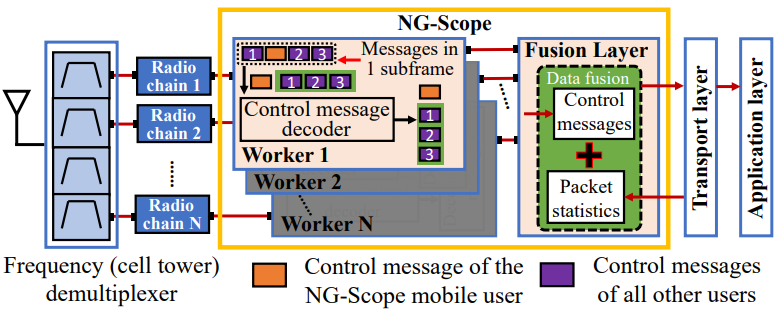
Image Source : NG-Scope: Fine-Grained Telemetry for NextG Cellular Networks
Followings are breakdown of the system and descriptions on each component
Frequency (Cell Tower) Demultiplexer - Input Signal: Signals from multiple base stations (cell towers) are received via an antenna.
- Demultiplexing: The received signals are separated into different radio chains, each corresponding to a specific frequency (or base station). This step ensures that the signals from multiple towers can be processed independently.
Radio Chains - Each radio chain represents a stream of data received from a specific cell tower.
- These streams are passed on to the NG-Scope system for further decoding.
NG-Scope: Multi-Worker Framework and Fusion Layer - NG-Scope operates in a parallelized architecture using multiple workers to decode control messages. Each worker processes signals from one radio chain.
- Worker Components:
- Control Message Decoder: Decodes the control channel messages in each subframe (1 ms of LTE transmission). It extracts the resource allocation and other relevant parameters for:
- NG-Scope's mobile user (highlighted in orange).
- All other users connected to the cell (highlighted in purple).
- Subframe-Level Processing: Each worker processes all control messages within a subframe and generates a complete list of decoded messages.
- Fusion Layer
- Data Fusion: The decoded control messages from all workers are combined with packet statistics (e.g., packet arrival times, delays) from the transport layer.
- The fusion layer aligns and integrates these multi-layer data sources to provide a detailed and synchronized view of:
- Resource allocations across all UEs.
- Millisecond-level capacity and traffic patterns for each UE.
Transport Layer and Application Layer - Transport Layer: Uses the fine-grained capacity estimates and decoded control information to optimize protocols such as congestion control and packet scheduling.
- Application Layer: Benefits from enhanced transport layer functionality, enabling better quality of service for applications like video streaming and real-time telephony.
Key Features of the architecture: - Parallel Processing: The use of multiple workers enables simultaneous decoding of control messages from different base stations.
- Cross-Layer Integration: By fusing physical layer control messages with transport layer statistics, NG-Scope offers a comprehensive view of network operations.
- Per-User Insights: It distinguishes between control messages for NG-Scope's mobile user and other users, enabling tailored analysis.
C-RNTI detection and DCI decoding
C-RNTI is a critical information to decode the DCI for a specific user. Most of other sniffers are trying to figure out C-RNTI by decoding RACH procedure. However NG-Scope uses a novel (interesting idea) to figure out C-RNTI without tracking RACH procedure.
Before looking into how NG-Scope figure out C-RNTI, let's briefly look into how C-RNTI is used in terms of DCI encode. It is illustrated as below.
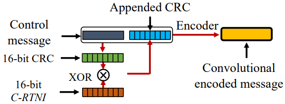
Image Source : NG-Scope: Fine-Grained Telemetry for NextG Cellular Networks
Here’s a step-by-step explanation of how C-RNTI is used in the context of DCI encoding and decoded by NG-Scope:
Control Message Preparation: - The LTE base station creates a control message containing scheduling and resource allocation information for a specific user.
CRC Calculation: - A 16-bit CRC (Cyclic Redundancy Check) is calculated based on the control message to ensure its integrity during transmission.
XOR with C-RNTI: - The calculated CRC is XOR-ed with the 16-bit C-RNTI of the target UE, uniquely associating the message with that UE.
Appending CRC: - The XOR-ed CRC is appended to the control message, forming an extended message.
Convolutional Encoding: - The extended message undergoes convolutional encoding, which adds redundancy for error correction, making the message more robust during transmission.
Following is the technique that is used in NG-Scope to figure out C-RNTI. It is a kind of automatic reverse engineering from the received DCI and the received CRC masked with C-RNTI.
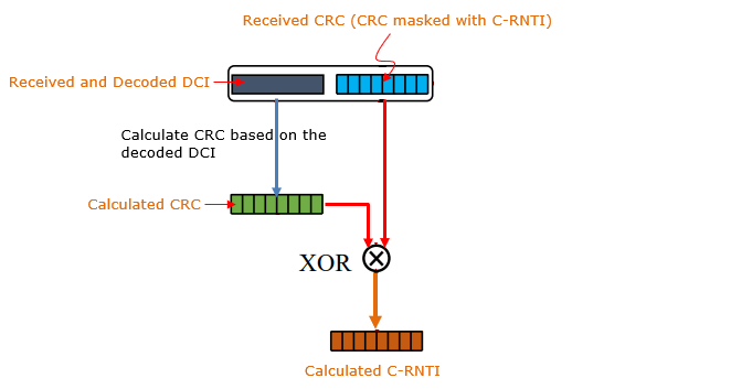
Here is the expanded explanation of how NG-Scope figures out the C-RNTI:
Decoding the DCI Message: - NG-Scope starts by decoding the Downlink Control Information (DCI) message directly from the received signal.
- This is just decoding DCI message without validating with the appended CRC.
Calculating CRC: - After decoding the DCI message, NG-Scope calculates the Cyclic Redundancy Check (CRC) for the decoded message.
Comparing with Masked CRC(the masked CRC appended by eNB): - The calculated CRC is compared to the masked CRC that was appended to the DCI message by the eNB (base station). The masking process involves XORing the original CRC with the C-RNTI during the encoding process.
Deriving C-RNTI: - To extract the C-RNTI, NG-Scope performs a XOR operation between the calculated CRC and the masked CRC. This operation effectively removes the CRC applied by the base station, leaving the original C-RNTI.
Verifying the Derived C-RNTI: - Once the C-RNTI is derived, NG-Scope verifies its validity using additional methods. One such method involves tracking the activity of the user associated with the derived C-RNTI. If the corresponding user exhibits consistent activity, such as transmitting or receiving data, it increases confidence that the derived C-RNTI is correct.
Key Innovation: - The most notable aspect of NG-Scope's approach is its ability to decode the DCI message without prior knowledge of the C-RNTI. Instead, the C-RNTI is deduced later in the process by analyzing the relationship between the calculated CRC and the masked CRC, allowing for comprehensive decoding of control messages even in scenarios where user-specific identifiers are unknown.
Once a verified C-RNTI is obtained, it is utilized to decode DCI messages and verify it directly with C-RNTI. The process leverages a structured tree representation of all possible aggregation levels (L) within the control channel, which helps reduce the computational overhead typically associated with blind decoding.
The control channel is organized into Control Channel Elements (CCEs), grouped at different aggregation levels (L=1, 2, 4, 8). Each CCE represents a basic building block of the control channel, and higher aggregation levels correspond to groups of multiple CCEs. For example:
- L=1 represents individual CCEs.
- L=2, 4, 8 represent groups of 2, 4, and 8 consecutive CCEs, respectively.
This hierarchical tree structure, combined with depth-first search and LLR-based pruning, enables NG-Scope to decode control messages with minimal overhead, making the process both efficient and precise. This approach is particularly effective in handling the dynamic and resource-intensive nature of LTE control channel decoding
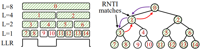
Image Source : NG-Scope: Fine-Grained Telemetry for NextG Cellular Networks
Following is overall procedures of DCI decoding based on the tree based on blind decoding
Tree Representation: - The decoding process is visualized as a hierarchical tree, where the root node corresponds to the highest aggregation level (L=8), and leaf nodes represent individual CCEs at the lowest aggregation level (L=1).
- Each level of the tree corresponds to a different aggregation level, and the parent node aggregates its child nodes.
Depth-First Search with C-RNTI: - Once the C-RNTI is obtained, it is used to decode control messages efficiently.
- NG-Scope traverses the tree using a depth-first search (DFS) strategy. It starts at the highest aggregation level (L=8) and descends down the tree, decoding only the branches that match the C-RNTI.
- If a valid match is found (RNTI matches at a node), the decoding process skips the child nodes of that branch since the data has already been decoded.
Log-Likelihood Ratio (LLR) Pruning: - NG-Scope uses LLR-based pruning to further reduce the search space. If the LLR values of a node or its children indicate that the CCEs contain no valid control information (likely empty), those nodes are skipped entirely.
Efficiency Gains: - By using the C-RNTI to guide the tree traversal, NG-Scope avoids blindly decoding every possible combination of CCE locations and aggregation levels.
- This drastically reduces the scope of decoding, saving computational resources while maintaining high accuracy in decoding DCI messages.
Implementation Example : 5G Scope
5GSniffer is an open-source tool that can capture and decode the control channel of 5G networks. It is the first of its kind to provide detailed information about how resources are scheduled for all users in a live 5G cell. Older 4G (LTE) sniffers were easier to make because 4G control signals were simpler. 5G is more complex. It schedules resources in many different ways, encrypts important messages, and doesn't have easy-to-find indicators(e.g, PCFICH) in 4G. To handle this, 5GSniffer was built from scratch to be efficient and handle large amounts of data. It uses clever methods to figure out important information like ScramblingID and RNTI. It can also use multiple computer processors and even work across multiple computers to analyze data quickly. By quietly listening and smartly figuring things out, 5GSniffer helps researchers and security experts understand how 5G networks work.
Overall Flow of 5G Scope
The flow of operations for the 5GSniffer tool is as follows. The final goal of the tool is to processes and decodes the 5G control channel data to extract Downlink Control Information (DCI). This process efficiently captures, synchronizes, maps, and decodes the 5G control channel data in parallel, allowing the tool to extract vital network information in real time.
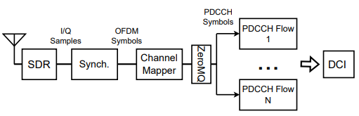
Image Source : From 5G Sniffing to Harvesting Leakages from Privacy-Preserving Messengers
The breakdown and the description of each components are as follows :
SDR (Software-Defined Radio): - The SDR acts as the input device that captures raw radio signals (I/Q samples) from the 5G network. These samples represent the digitized version of the radio frequency signals.
Synchronization (Synch.): - This block is responsible for finding and synchronizing with a 5G cell. It locates the Synchronization Signal Block (SSB) broadcast by the gNB and aligns the captured signal in time and frequency. It also demodulates the received OFDM symbols, preparing them for further processing.
Channel Mapper: - After synchronization, the Channel Mapper identifies the specific OFDM symbols that contain PDCCH information. This is based on the CORESET configuration, which specifies where the PDCCH symbols are located.
ZeroMQ: - ZeroMQ is used here as a messaging system to distribute the identified PDCCH symbols to multiple parallel processing threads. This allows for efficient and scalable decoding by splitting the workload.
PDCCH Flows: - Each thread or flow processes a subset of the PDCCH symbols. This includes tasks such as correlating with PDCCH-DMRS pilots, descrambling, and decoding the Downlink Control Information (DCI).
DCI (Downlink Control Information): - The final output of the flow is the decoded DCI. The DCI contains crucial scheduling and resource allocation information for 5G users in the cell.
Challenges
Understanding 5G control signals is very difficult because 5G networks are complex and flexible. Unlike older 4G (LTE) networks, 5G uses encrypted signals, changes a lot in terms of the mechanism , and doesn't have simple indicators(e.g, PCFICH) that were used in 4G. This makes it much harder to listen in passively. Also, important information like ScramblingID and RNTI( needed to understand control messages) are hidden. Figuring these out requires clever methods, not just guessing. It's also harder to estimate the signal quality without special reference signals, and the huge amount of unknown information makes the calculations very complex. To solve these problems, a tool needs to be very well designed, smart, and able to handle large amounts of data. 5GSniffer is designed to do just that, allowing us to understand the details of 5G control signals.
Followings are summarized list of these challenges :
CORESET and PDCCH Configuration: - Unlike LTE, 5G does not have a straightforward indicator like PCFICH to locate PDCCH. The configuration (CORESET resources, OFDM symbols, and Aggregation Levels) is signaled through encrypted RRC messages, which are not accessible to a passive sniffer.
Unknown ScramblingID and RNTI: - These parameters are critical for decoding DCI but are encrypted or implicitly configured in 5G. ScramblingID is used in the scrambling sequence for DMRS generation, while RNTI is used for CRC masking and descrambling. A brute-force approach for these parameters would involve an impractical 2^44 combinations.
Variable DCI Size: - DCI formats have variable sizes (12–140 bits), and without knowing the exact size, the sniffer cannot efficiently decode DCI. This increases complexity, as different sizes require different decoding configurations.
High False Positive Rate: - Without knowing all parameters, a brute-force approach leads to many false positives, where incorrect DCI decodings pass the CRC check, making it hard to identify valid DCIs.
Channel Estimation: - The absence of periodic cell-wide reference signals (like in LTE) means the sniffer must estimate the channel using interleaved DMRS pilots. However, DMRS sequences depend on the unknown ScramblingID, complicating channel estimation.
Computational Complexity: - The need to decode multiple DCIs across different PDCCH regions with unknown parameters leads to significant computational overhead.
Solutions
Decoding 5G control signals is hard, so we need clever solutions, not just guessing. 5GSniffer uses several advanced techniques to solve problems like figuring out hidden user IDs and scrambling codes, dealing with different message sizes, and handling huge amounts of data quickly and accurately. It uses a method based on special reference signals (DMRS) to find the scrambling code, takes advantage of repeated information in the control messages, and keeps a prioritized list of user IDs. This makes it much more efficient. It also uses pre-calculated network settings and processes data using multiple computer threads for speed and real-time performance. By cleverly using other available information and optimizing how it estimates signal quality, 5GSniffer can effectively decode control channel data. This helps us understand how 5G networks work.
Following is the illustrated summary of the solutions to the challenges listed before
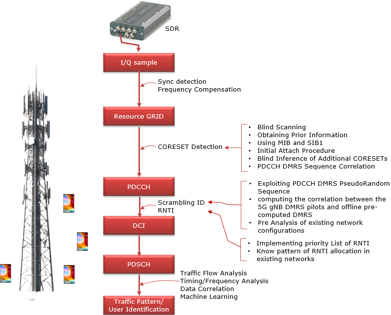
Followings are descriptions on how 5G Sniffer resolves the challenges listed before
Resource Grid Construction - Challenge: Identifying the resource grid structure, including the CORESET configuration.
- Solution:
- Blind scanning is used to detect active 5G networks without prior knowledge.
- MIB (Master Information Block) and SIB1 (System Information Block 1) decoding provides initial CORESET configuration and bandwidth information.
- Initial Attach Procedure (without requiring SIM registration) enables access to the RRC Setup message for further configuration.
- Blind inference of additional CORESETs is performed using correlation with precomputed PDCCH DMRS sequences.
CORESET Detection - Challenge: Determining the CORESET parameters, such as frequency and time-domain allocations.
- Solution:
- PDCCH DMRS Sequence Correlation is used to identify CORESET configurations efficiently, bypassing brute-force methods.
- Pre-analysis of existing network configurations leverages knowledge of common CORESET setups used by operators to reduce detection time.
PDCCH Decoding - Challenge: Extracting ScramblingID and RNTI for successful DCI decoding.
- Solution:
- The sniffer exploits the pseudo-random nature of the PDCCH DMRS sequence to deduce ScramblingID.
- Correlation between gNB DMRS pilots and offline precomputed DMRS sequences is computed to identify ScramblingID accurately.
- A priority list for RNTI is implemented to speed up decoding by focusing on the most likely active RNTIs based on prior detections.
DCI Decoding - Challenge: Decoding DCIs efficiently with minimal false positives.
- Solution:
- Rate-matching optimizations exploit redundancy in DCI encoding to identify valid scrambling sequences without completing the full decoding chain.
- The sniffer reduces the number of CCEs and Aggregation Levels (ALs) for decoding based on DMRS correlation results, significantly improving efficiency.
Implementation Example : NR Scope
NR-Scope is a tool for monitoring 5G Standalone (SA) networks. It helps developers and researchers understand how the radio network allocates resources. Unlike traditional methods, it does not need cooperation from network operators or mobile devices. Instead, it listens to radio signals and decodes control messages.
NR-Scope provides real-time information on throughput, latency, and retransmissions. It works on software-defined radios (SDRs) The tool gives very accurate results, with an error rate of less than 0.1% in some cases.
Highlight of Functionality
The tool passively decodes unencrypted DCI and RRC messages broadcast by 5G base stations (gNBs) to estimate per-user throughput, latency, retransmissions, and spare network capacity. By tracking user equipment (UE) associations via identifiers like C-RNTI and leveraging physical-layer scheduling data, NR-Scope enables real-time, millisecond-scale insights into RAN behavior, outperforming existing tools limited to 4G or single-UE perspectives.
NR-Scope enables fine-grained telemetry for 5G applications. It helps with network-aware application adaptation, congestion control, and security monitoring. It provides millisecond-level network insights that improve performance tuning for video streaming, cloud gaming, and other low-latency applications.
Passive 5G SA Telemetry Tool - Monitors network performance without modifying the network or UE.
- Captures radio control messages and scheduling information.
Throughput, Latency, and Retransmission Estimation - Provides real-time insights at the millisecond level.
- Detects spare capacity in the RAN.
Decodes Key 5G Control Messages - NR SA Cell Search and MIB decoding
- Unencrypted Radio RRC (SIBs and RRC Setup) for UE association tracking (C-RNTI).
- DCI for scheduling and resource allocation.
- Physical Resource Block (PRB) usage, Modulation and Coding Scheme (MCS), and HARQ retransmissions.
Works on Software-Defined Radios (SDRs) - Operates on srsRAN, Aether Onramp, Amarisoft Callbox, and T-Mobile cells.
- Does not require cooperation from mobile operators or device manufacturers.
PHY capability - Both FDD and TDD support
- Support SCS 15Khz and 30 Khz (according to GitHub Description)
- Support of Bandwidth greater than 20 Mhz (The paper does not explictely mentioned about the maximum bandwidth it supports. The description on GitHub says it supports upto 40Mhz)
Multi UE support - Max 64 UEs (according to GitHub Description)
Supports Multiple Use Cases - Network-aware application tuning (e.g., cloud gaming, video streaming).
- Congestion control by providing real-time channel conditions.
- Security monitoring (detecting abnormal RAN behavior).
System Overview and Mechanism
NR-Scope consists of both hardware components and a software architecture that work together to capture, decode, and analyze 5G SA network telemetry.
The hardware component is based on a USRP (Universal Software Radio Peripheral) software-defined radio (SDR), which acts as a passive receiver to listen to signals from a 5G gNB. The USRP captures raw radio frequency (RF) signals and converts them into digital samples for processing. The system also requires a host computer, which runs the NR-Scope software for signal decoding and data extraction.
The software architecture is designed to process the received RF signals in multiple steps. The first step involves radio signal sampling, where the USRP digitizes the received waveforms. These samples are then processed by the NR-Scope pipeline, which includes automatic gain control (AGC), resampling, and synchronization to align with the 5G frame structure.
NR Scope is made up of the hardware setup used in the evaluation of NR-Scope across different 5G Standalone network deployments. It includes various components necessary for implementing and testing NR-Scope in both open-source and industrial 5G environments. The setup demonstrates how the telemetry tool integrates with existing systems and interacts with the network.
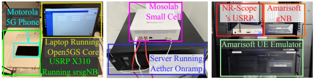
Image Source : NR-Scope: A Practical 5G Standalone Telemetry Tool
Followings are short descriptions on each hardware components
-
Motorola 5G Phone: Acts as a user equipment (UE) to connect with the 5G network for testing purposes.
-
Laptop with Open5GS Core: Runs the Open5GS software core and srsRAN gNB implementation. A USRP X310 SDR captures and processes signals in this setup.
-
Mosolab Small Cell: Provides a private 5G SA network environment for testing. This small cell connects to a server running the Aether Onramp 5G software-defined core.
-
Amarisoft Setup: Includes an Amarisoft gNB and UE Emulator. NR-Scope's USRP is connected to this environment to capture and decode radio signals for evaluation.
-
Server Running Aether Onramp: Handles the core network functionalities for the Mosolab small cell.
- NR-Scope: The core telemetry tool running on a laptop or server, passively decoding DCI and RRC messages from the gNB to monitor UE activity, throughput, and retransmissions.
- USRP X310: A high-performance software-defined radio (SDR) that captures raw 5G signals from the gNB for NR-Scope’s processing.
- srsgNB: A software-defined 5G base station (from the srsRAN project) running on a server, emulating real-world RAN behavior and scheduling.
- Open5GS Core: An open-source 5G core network handling authentication, session management, and data routing between UEs and external networks. This works with srsgNB to support the full 5G stack from RAN through Core.
- Aether Onramp: An ONF project providing edge-cloud orchestration for private 5G networks, integrating with NR-Scope to enable RAN-aware application deployment.
NR Scope implemented its own system processing pipeline of NR-Scope, detailing how it processes radio signals received from a 5G base station (gNB) to extract telemetry data. The pipeline involves multiple stages, starting from signal reception by the USRP (Universal Software Radio Peripheral) to the generation of telemetry results such as RRC messages, DCI, and new UE information.
This pipeline is designed to operate asynchronously, using multi-threading to handle high data throughput and ensure real-time telemetry processing. The output includes detailed insights into 5G network performance and behavior.
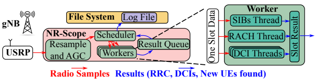
Image Source : NR-Scope: A Practical 5G Standalone Telemetry Tool
Followings are the breakdown and descriptions of the pipeline
-
Signal Input (USRP):
-
The USRP receives raw radio signals from the 5G base station (gNB) and converts them into digital samples for processing.
-
Pre-Processing (NR-Scope):
-
Resample and AGC: Adjusts the sampling rate and signal strength using Automatic Gain Control (AGC) to ensure signal quality.
-
Scheduler: Manages tasks and distributes processing workloads to available worker threads.
-
Workers: Handle specific tasks for telemetry extraction and decoding.
-
Worker Threads:
-
SIBs Thread: Decodes System Information Blocks (SIBs) for cell configuration and system parameters.
-
RACH Thread: Tracks the Random Access Channel (RACH) process to identify new UEs and assign C-RNTI.
-
DCI Threads: Decode Downlink Control Information (DCI) to monitor resource allocation and throughput.
-
Result Management:
-
Result Queue: Collects data processed by workers and prepares it for logging or real-time use.
-
File System and Log File: Stores results such as decoded RRC messages, DCI, and new UE discoveries for analysis.
NR-Scope Workflow
The workflow of NR-Scope is made up of three main phases, showcasing how it tracks user equipment (UEs) and extracts telemetry data in a 5G Standalone (SA) network. It starts with acquiring essential cell and UE-specific information, continues with decoding control and data transmissions for UEs, and culminates in throughput and resource estimation for the connected devices. Each phase demonstrates the progressive steps NR-Scope follows to provide fine-grained network telemetry.
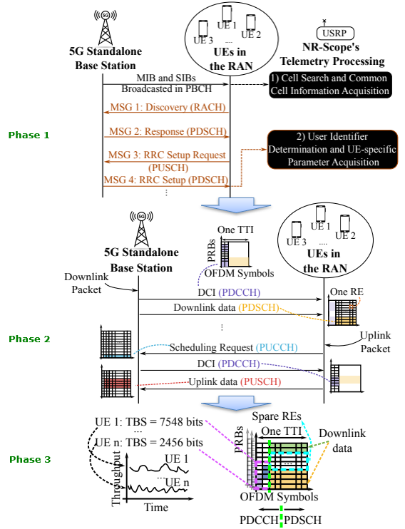
Image Source : NR-Scope: A Practical 5G Standalone Telemetry Tool
Following is the breakdown and descriptions of the illustration shown above
-
Phase 1: Cell and UE Information Acquisition -
The 5G Standalone base station broadcasts Master Information Blocks (MIBs) and System Information Blocks (SIBs) in the Physical Broadcast Channel (PBCH).
-
NR-Scope processes these to identify the cell configuration and common cell parameters required for synchronization.
-
The Random Access Channel (RACH) procedure takes place:
-
MSG 1: Discovery by UEs through RACH.
-
MSG 2: Response from the base station on the Physical Downlink Shared Channel (PDSCH).
-
MSG 3: RRC Setup Request from UEs on the Physical Uplink Shared Channel (PUSCH).
-
MSG 4: RRC Setup information, including UE-specific parameters, sent from the base station on PDSCH.
-
NR-Scope tracks UE associations by extracting C-RNTI and UE-specific parameters from MSG 4.
Phase 2: Telemetry Extraction -
Within each Transmission Time Interval (TTI):
-
The base station schedules downlink and uplink transmissions using the Physical Downlink Control Channel (PDCCH).
-
Downlink packets are sent on the PDSCH, while uplink packets are received on the PUSCH.
-
NR-Scope decodes DCI (Downlink Control Information) to monitor resource allocation, scheduling information, and data rates for each UE.
-
Scheduling requests from UEs on the Physical Uplink Control Channel (PUCCH) are tracked to understand uplink data requirements.
Phase 3: Throughput and Resource Estimation -
NR-Scope calculates the Transport Block Size (TBS) for each UE based on the decoded DCI.
-
Example: UE 1 receives 7548 bits, while UE n receives 2456 bits in a given TTI.
-
It identifies spare resource elements (REs) in the system, estimating the network's unused capacity.
-
The tool provides a time-series analysis of throughput, resource allocation, and scheduling efficiency for each UE, enabling insights into the network's performance and load.
Limitations
NR-Scope is a passive telemetry tool for 5G Standalone (SA) networks that focuses on real-time monitoring of radio resource allocation and network performance. It decodes Downlink Control Information (DCI) and unencrypted RRC messages to track resource usage and retransmissions without requiring cooperation from network operators or UEs. However, NR-Scope has notable limitations, including its dependency on the RACH process for C-RNTI discovery, inability to decode encrypted RRC messages, and restricted RF bandwidth, which may not support the full spectrum of 5G deployments. Additionally, it focuses solely on PDCCH decoding, with no capability to decode user-plane data from PDSCH or PUSCH, and it lacks support for advanced RAN features such as inter-cell coordination and uplink telemetry. Despite these constraints, NR-Scope offers valuable insights for specific use cases in 5G telemetry.
-
Dependency on the RACH Process for C-RNTI Discovery : NR-Scope relies on decoding the Random Access Channel (RACH) process to obtain the C-RNTI. Missing the RACH process prevents NR-Scope from tracking subsequent DCIs for that UE, limiting its ability to monitor new user associations. -
Decoding Only Unencrypted RRC Messages : NR-Scope is restricted to decoding unencrypted Radio Resource Control (RRC) messages. Encrypted RRC signaling in secure networks reduces its ability to gather telemetry from advanced or private deployments. -
RF Bandwidth Limitation : The tool’s performance is limited by the radio frequency bandwidth supported by the SDR hardware. For example, USRPs used in NR-Scope have a finite RF bandwidth, which might not cover wider 5G carrier bandwidths (e.g., 100 MHz in certain bands), leading to incomplete capture of control signals. (NOTE : Even thought the paper hinted about potential support for wider bandwidth width, it does not explicitely mentions about the maximum bandwidth it supports. All the examples described in the paper is with 20Mhz or under) -
Focus on PDCCH (DCI) Decoding Only : NR-Scope primarily decodes the PDCCH to extract DCIs, providing insights into control signaling but not directly decoding the user data transmitted on the PDSCH (downlink) or PUSCH (uplink). This limits its analysis of actual data throughput and user-plane performance. -
No Uplink Data Decoding : While NR-Scope tracks uplink scheduling via PDCCH, it does not decode uplink data transmissions on the PUSCH, which restricts insights into UE-specific uplink behavior and channel usage. -
Missed Metrics from Advanced RAN Features : NR-Scope currently focuses on basic RAN telemetry, such as throughput and resource allocation, and does not capture advanced features like inter-cell coordination, carrier aggregation, or beam management.
Reference
- 5G NR Jamming, Spoofng, and Sniffng:Threat Assessment and Mitigation (2018)
- FALCON: An Accurate Real-time Monitor for Client-based Mobile Network Data Analytics (2020)
- NG-Scope: Fine-Grained Telemetry for NextG Cellular Networks (2022)
- LTESniffer: An Open-source LTE Downlink/Uplink Eavesdropper (2023)
- From 5G Sniffing to Harvesting Leakages from Privacy-Preserving Messengers (2023)
- NR-Scope: A Practical 5G Standalone Telemetry Tool (2024)
YouTube
- LTESniffer: An Open-source LTE Downlink/Uplink Eavesdropper - ACM WiSec (2023)
OpenSource
- 5GSniffer - Spritelab
- LTE Sniffer - SysSec KAIST
- srsLTE-Sniffer - Wooniety
- NG Scope - Princeton
- NR Scope - Princeton