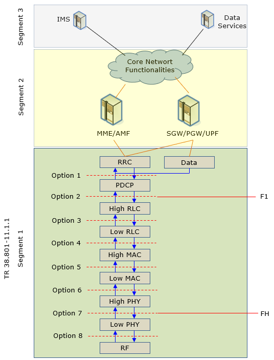
Overall structure of the whole network would look like follows (at least to me -:)). I know it is too much simplified at CoreNetwork part... but I think this is good enough for OpenRAN since it is mostly about RAN, not about Core Network. The only important part of Core Network in this context would be the interface to RAN part which is shown in this illustration.
Now let's look into RAN part which is labeled as Segment 1. Probably the ideal (maximum) level of modularization and separation of RAN can be something as shown below (Segment 1) which is described in 3GPP 38.801. If we can provide industry standard interface at all the split level labeled as Option 1 ~ 8, we may implement RAN with the components from all over the provides and put them together as lego block. But in practice, it may be a little overkill to define too many interfaces like this at this point. In most of OpenRAN standization and implementation, we focus mostly on Option 7 and 2 (In some SDR based implementation especially for LTE, Option 8 is also a common interface). Actually in recent Open RAN activities, Option 7 has been evolved into a few different flavours and the most popular one is 7.2x.
O-RAN Architecture
The architecture of a RAN defined by O-RAN specification looks as below. The blue part shown below indicates the components that are commonly defined in 3GPP as well.
The Open FH interface (the interface between O-DU and O-RU) corresponds to Option 7 and F1 interface corresponds to Option 2. As you see here, the interface between DU and CU and the interfaces among other RANs (e.g, X2, Ng, Xn etc) are also commonly defined by 3GPP.
Following diagram represents the logical architecture of O-RAN (Open Radio Access Network) which is from O-RAN specification document. Each of these blocks interacts through various interfaces, which are defined by the O-RAN Alliance and standardized to ensure interoperability and flexibility in the deployment and management of the network components.
< Figure 4.1 2: Logical Architecture of O-RAN >
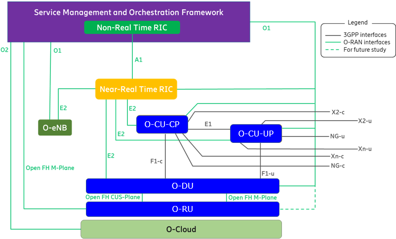
Source : O-RAN.WG1.O-RAN-Architecture-Description
Components and Interfaces
Each block in the diagram represents a different component or function within the architecture. Here's a breakdown of each block:
-
Service Management and Orchestration Framework : This is the overarching framework for managing and orchestrating the O-RAN network. It includes tools and protocols for service management to ensure that the network is efficient, reliable, and can adapt to changing conditions and demands. Non-Real Time RAN Intelligent Controller (RIC) : This component handles tasks that require a broader view of the network and can tolerate a longer delay (non-real-time). It performs functions like policy-based guidance, model training for AI, and non-real-time analytics.Near-Real Time RIC : This works on a shorter timescale than the non-real-time RIC and deals with functions that need to react more quickly to changes in the network. It handles tasks such as load balancing, radio resource management, and interference management.O-eNB : Represents an O-RAN-enabled eNodeB(eNB in LTE and gNB in NR). It is part of the traditional cellular network infrastructure adapted to fit into the open architecture of O-RAN.O-CU-CP (Central Unit Control Plane) : This component is part of the Central Unit in O-RAN that handles the control plane functions. It is responsible for setting up and managing network connections.O-CU-UP (Central Unit User Plane) : This is another part of the Central Unit that specifically handles user data traffic. It deals with the transmission and routing of user data across the network.O-DU (Distributed Unit) : The Distributed Unit processes the real-time data at the edge of the network. It handles functions like real-time radio signal processing and forwarding data between the radio units and the central units.O-RU (Radio Unit) : This is the radio unit that handles all radio transmission and reception. It converts the digital signals from the O-DU into radio waves and vice versa.O-Cloud : This represents the cloud infrastructure that supports the O-RAN architecture. It provides the computational resources and storage necessary for processing, managing, and analyzing data within the network.
The interfaces shown in the diagram you provided can be categorized into three groups: 3GPP interfaces, O-RAN interfaces, and interfaces marked for future study. Here's an explanation for each type of interface
3GPP Interfaces : These are standardized interfaces defined by the 3rd Generation Partnership Project (3GPP), which is responsible for setting standards for mobile telecommunications. In your diagram, these interfaces are marked with solid black lines. They include:X2-c and X2-u : These interfaces connect different types of base stations. The "X2" interface in LTE architecture facilitates communication between two eNBs (evolved Node Bs), handling control (X2-c) and user (X2-u) plane traffic.NG-u and NG-c : These are part of the 5G architecture, connecting the gNodeB (gNB) to the 5G Core Network. NG-u handles user plane data, while NG-c deals with the control plane.Xn-c and Xn-u : Similar to X2, but these interfaces are specific to 5G NR (New Radio). Xn-c is for the control plane, and Xn-u is for the user plane, linking different gNBs.O-RAN Interfaces : These interfaces are specific to the O-RAN architecture, facilitating open and interoperable connections between different parts of the RAN. They are depicted with dashed green lines in your diagram. These include:E1 Interface : This interface connects the O-CU-CP (Central Unit Control Plane) to the O-CU-UP (Central Unit User Plane). It facilitates communication and coordination between these two components of the Central Unit, managing control and user plane functionalities within the network.E2 Interface : The E2 interface links the Near-Real Time RIC with other key RAN components such as the O-CU-CP, O-CU-UP, O-DU (Distributed Unit), and O-eNB (enhanced Node B). It enables the Near-Real Time RIC to execute control functions and real-time optimization across these network elements.A1 Interface : This interface is established between the Non-Real Time RIC and the Near-Real Time RIC. It is used for policy management and strategic guidance, allowing the Non-Real Time RIC to send higher-level directives and objectives to the Near-Real Time RIC.F1 Interface : The F1 interface has two components:- F1-c: Connects the O-CU-CP to the O-DU, handling control plane communications.
- F1-u: Connects the O-CU-UP to the O-DU, responsible for transmitting user plane data.
FH Interface : The FH interface consists of:- Between O-DU and O-RU (Radio Unit): Manages the forwarding of data and control signals.
- Between Service Management/Orchestration Framework and O-RU: Facilitates the orchestration and management of radio units, supporting operations like deployment, configuration, and maintenance.
O1 Interface : This interface links the Service Management and Orchestration Framework with the O-DU and O-CU components. It supports the orchestration and operational management of these units, enhancing flexibility and responsiveness in network operations.O2 Interface : Connects the Service Management and Orchestration Framework to the O-Cloud. This interface is crucial for managing cloud resources and services, aiding in the overall orchestration and efficiency of cloud-based network functions.Interfaces for Future Study : These are subject for future development and standardization within the O-RAN community. They might include additional functionality or enhancements to existing interfaces to support new technologies or operational requirements.
What is RIC ?
The RAN Intelligent Controller (RIC) is a software-defined component of the Open Radio Access Network (Open RAN) architecture responsible for controlling and optimizing RAN functions. It's a critical piece of the Open RAN disaggregation strategy, bringing multivendor interoperability, intelligence, agility, and programmability to radio access networks. The RIC is a key enabler of Open RAN, providing a flexible, scalable, and programmable platform for managing and optimizing the RAN. By using the RIC, mobile operators can improve network performance, increase flexibility and agility, and reduce costs.
Key points about RIC:
-
Centralized intelligence : The RIC provides a centralized platform for managing and optimizing the RAN, enabling more efficient resource allocation and improved network performance. Open and programmable : The RIC is designed to be open and programmable, allowing mobile operators to customize and optimize the RAN for their specific needs.Application-based : The RIC can host a variety of applications, called xApps and rApps, that can be used to automate and optimize RAN operations.Near-Real-Time and Non-Real-Time : There are two types of RICs: the near-real-time RIC (near-RT RIC) and the non-real-time RIC (non-RT RIC). The near-RT RIC is responsible for making fast control decisions, while the non-RT RIC is responsible for longer-term optimization and management tasks.
Benefits of using RIC:
Improved network performance : The RIC can help to improve network performance by optimizing resource allocation, reducing interference, and improving load balancing.Increased flexibility and agility : The RIC enables mobile operators to quickly adapt to changing network conditions and user demands.Reduced costs : The RIC can help to reduce costs by automating RAN operations and optimizing resource utilization.
xApp vs rApp
xApps and rApps are both applications designed to run on the RAN Intelligent Controller (RIC) in an Open RAN architecture, but they serve different purposes and operate on different timescales:
-
xApps (near-Real-Time RIC applications): -
Execution : Run on the near-RT RIC. -
Timescale : Designed for fast, near-real-time decision-making and control actions, typically within milliseconds or seconds. -
Function : Focus on optimizing radio resources, managing interference, scheduling traffic, and other tasks requiring immediate responses to network conditions. -
Examples : Radio Resource Management (RRM) optimization, load balancing, mobility management, and Quality of Service (QoS) enforcement. -
rApps (Non-Real-Time RIC applications): -
Execution : Run on the non-RT RIC. -
Timescale : Operate on a longer timescale, ranging from seconds to minutes or even hours. -
Function : Focus on policy-based decisions, higher-level optimization, data analytics, machine learning, and other tasks that don't require immediate responses. -
Examples : Energy saving, network slicing, anomaly detection, performance analysis, and long-term resource optimization. -
Key Differences
|
Feature |
xApps |
rApps |
|---|---|---|
|
RIC Type |
near-RT RIC |
non-RT RIC |
|
Timescale |
Milliseconds to seconds |
Seconds to minutes or hours |
|
Focus |
Real-time control and optimization |
Policy-based decisions and higher-level optimization |
|
Examples |
RRM, load balancing, mobility management |
Energy saving, network slicing, anomaly detection |
-
Interaction: -
xApps and rApps can work together to provide a comprehensive solution for RAN optimization. rApps can analyze data and provide policy recommendations to xApps, which then implement these policies in real-time to optimize network performance.
O-RAN Specifications
Followings are the list of OpenRAN specification from O-RAN allience. This is just a list for you to do quick check on what kind of subjects are specified. You can download each of the specification from O-RAN allience specification site.
|
WG1: Use Cases and Overall Architecture Workgroup |
|
|
O-RAN Architecture Description |
|
|
O-RAN Operations and Maintenance Architecture |
|
|
O-RAN Operations and Maintenance Interface |
|
|
O-RAN Use Cases Detailed Specification |
|
|
O-RAN Use Cases Analysis Report |
|
|
O-RAN Slicing Architecture |
|
|
O-RAN Study on O-RAN Slicing |
|
|
O-RAN Information Model and Data Models Specification |
|
|
WG2: The Non-Real-Time RAN Intelligent Controller and A1 Interface Workgroup |
|
|
O-RAN Non-RT RIC Architecture |
|
|
O-RAN A1 interface: Type Definition |
|
|
O-RAN AI/ML Workflow Description and Requirements |
|
|
O-RAN A1 interface: General Aspects and Principles |
|
|
O-RAN A1 interface: Application Protocol |
|
|
O-RAN A1 interface: Transport Protocol |
|
|
O-RAN Non-RT RIC & A1 Interface: Use Cases and Requirements |
|
|
O-RAN Non-RT RIC: Functional Architecture |
|
|
WG3: The Near-Real-Time RIC and E2 Interface Workgroup |
|
|
O-RAN Near-RT RAN Intelligent Controller Near-RT RIC Architecture |
|
|
O-RAN Near-Real-time RAN Intelligent Controller Architecture & E2 General Aspects and Principles |
|
|
O-RAN Near-Real-time RAN Intelligent Controller, E2 Application Protocol |
|
|
O-RAN Near-Real-time RAN Intelligent Controller E2 Service Model |
|
|
O-RAN Near-Real-time RAN Intelligent Controller E2 Service Model (E2SM), RAN Function Network Interface (NI) |
|
|
O-RAN Near-Real-time RAN Intelligent Controller E2 Service Model (E2SM) KPM |
|
|
WG4: The Open Fronthaul Interfaces Workgroup |
|
|
O-RAN Open Fronthaul Conformance Test Specification |
|
|
O-RAN Fronthaul Cooperative Transport Interface Transport Control Plane Specification |
|
|
O-RAN Fronthaul Interoperability Test Specification (IOT) |
|
|
O-RAN Fronthaul Control, User and Synchronization Plane Specification |
|
|
O-RAN Management Plane Specification |
|
|
O-RAN Cooperative Transport Interface Transport Management Plane Specification |
|
|
WG5: The Open F1/W1/E1/X2/Xn Interface Workgroup |
|
|
O-RAN O1 Interface specification for O-CU-UP and O-CU-CP |
|
|
O-RAN Interoperability Test Specification (IOT) |
|
|
O-RAN Transport Specification |
|
|
O-RAN NR C-plane profile |
|
|
O-RAN NR U-plane profile |
|
|
WG6: The Cloudification and Orchestration Workgroup |
|
|
O-RAN O-Cloud Notification API Specification for Event Consumers |
|
|
O-RAN O2ims Interface Specification |
|
|
O-RAN Acceleration Abstraction Layer FEC Profiles |
|
|
O-RAN Acceleration Abstraction Layer General Aspects an Principles |
|
|
O-RAN Orchestration Use Cases and Requirements for O-RAN Virtualized RAN |
|
|
O-RAN O2 General Aspects and Principles Specification |
|
|
O-RAN Cloud Platform Reference Design |
|
|
O-RAN Cloud Architecture and Deployment Scenarios for O-RAN Virtualized RAN |
|
|
WG7: The White-box Hardware Workgroup |
|
|
O-RAN Hardware Reference Design Specification for Indoor Pico Cell with Fronthaul Split Option 6 |
|
|
O-RAN Hardware Reference Design Specification for Indoor Picocell FR1 with Split Architecture Option 7-2 |
|
|
O-RAN Hardware Reference Design Specification for Indoor Picocell FR1 with Split Architecture Option 8 |
|
|
O-RAN Indoor Picocell Hardware Architecture and Requirement (FR1 Only) Specification |
|
|
O-RAN Deployment Scenarios and Base Station Classes |
|
|
O-RAN Hardware Reference Design Specification for Outdoor Micro Cell with Split Architecture Option 7-2 |
|
|
O-RAN Outdoor Micro Cell Hardware Architecture and Requirements (FR1) Specification |
|
|
O-RAN Hardware Reference Design Specification for Fronthaul Gateway |
|
|
O-RAN Outdoor Macrocell Hardware Architecture and Requirements (FR1) Specification |
|
|
WG8: Stack Reference Design Workgroup |
|
|
O-RAN Stack Interoperability Test Specification |
|
|
O-RAN Base Station O-DU and O-CU Software Architecture and APIs |
|
|
WG9: Open X-haul Transport Workgroup |
|
|
O-RAN Xhaul Transport Testing |
|
|
O-RAN Synchronization Architecture and Solution Specification |
|
|
O-RAN Management interfaces for Transport Network Elements |
|
|
O-RAN WDM-based Fronthaul Transport |
|
|
O-RAN Xhaul Packet Switched Architectures and Solutions |
|
|
WG10: OAM Workgroup |
|
|
O-RAN Operations and Maintenance Interface Specification |
|
|
O-RAN Operations and Maintenance Architecture |
|
Reference : Specification
- O-RAN Fronthaul Spilt Option 7-2x
- Understanding O-RAN: Architecture, Interfaces, Algorithms, Security, and Research Challenges - Arxiv (2022)