Duplexer is a device which enables us to connect both Tx path and Rx path to single/common antenna without interfering each other. In an FDD system such as LTE FDD, the UE transmits and receives at the same time on two different frequencies. So the transmitter and the receiver both stay connected to the antenna all the time, and something has to keep them apart. That something is the duplexer. On this page I'll show how it is built, why it is needed, what it looks like and how far a real duplexer is from the ideal one.
How Is a Duplexer Built?
A duplexer has three ports: one to the antenna, one to the receiver and one to the transmitter. How the inside is built depends on one question. Do the transmitter and the receiver use different frequencies, or the same frequency?
When the frequency of transmitter and reciever is different, it can be just a two filters combined together. One of the filter is tuned for the Reciever and the other for the Transmitter as illustrated below.

Figure 1. A filter based duplexer. Two band pass filters share the antenna port, and each one passes only the frequency of its own path.
The upper filter serves the receiver : its passband is drawn on the left of its box, at the lower frequency, and its output goes to the RF Reciever Path.The lower filter serves the transmitter : its passband is drawn further to the right, at a different frequency, and its input comes from the RF Transmiter Path.The antenna port carries both directions : the two arrows next to the antenna show the received signal going in and the transmitted signal coming out on the same line.
In the drawing the receive passband is the lower one. That is the arrangement of a base station duplexer, because a base station receives the uplink. In a UE duplexer it is the other way around, because in most FDD bands the UE transmits in the lower band and receives in the upper band. For example, 3GPP band 2 has the uplink at 1850 MHz - 1910 MHz and the downlink at 1930 MHz - 1990 MHz, so on the UE side the transmit filter is the lower one.
When the frequency of transmitter and reciever is same, filter method will not work. In this case, we use circulator which can pass the signal only in one direction as shown below.

Figure 2. A circulator based duplexer. The circulator routes each signal by its direction of travel instead of by its frequency.
The arrow inside the circulator shows the rotation. A signal from the transmitter path goes to the antenna, and a signal from the antenna goes to the receiver path. But a real circulator does not isolate its ports perfectly, and a mismatched antenna reflects part of the transmit signal straight into the receiver port. So a circulator alone gives much less isolation than a pair of filters at well separated frequencies. It is used where filters cannot help, as in radar or in same-frequency full duplex, and usually needs further cancellation after it. A TDD system does not need either device, because it transmits and receives at different times, so a switch connects the antenna to one path at a time.
Different frequencies use filters : this is the normal FDD duplexer.The same frequency needs a direction-based device : a circulator separates the paths by the direction of travel, with limited isolation.TDD uses a switch : transmission and reception never overlap in time, so no duplexer is needed.
Why we need a duplexer ?
The easy answer to this question may come from thinking about the case where you don't have the duplexer and both RF reciever path and Transmitter directly connected to the common (single) antenna.
The problem has two directions, so let's take them one at a time. First comes the transmit signal leaking into the receiver, which is the serious case. Then comes the received signal leaking into the transmitter.
Let's first think of what would happen to the transmitting signal. By design, most portions of the signal would go through the antenna but a small fractions of the signal would spill over to the reciever path. The amount of this spilled over signal would be very small but it can be pretty serious interference to the reciever path since the reciever path is designed to respond to the very low signal strength. In most wireless communication, the signal arriving at the reciever path is usually very low. So the receiver path should be designed to handle/process such a weak signal. Because of this property of reciever path, even the small signal spilled over from the transmitter can be very serious interference or it can even damage the reciever path in worst case.

Figure 3. Without a duplexer, the strong transmit signal reaches the receiver directly through the shared junction.
However if you put a duplexer as shown below. The signal spilled over from transmitter cannot get into the reciever path because it is blocked by the filter which pass only the reciever frequency signal.

Figure 4. With a duplexer, the receive filter blocks the transmit frequency, so the leaked signal stops at the cross.
Let's put numbers on it. A UE of power class 3 transmits 23 dBm. The top plot in Figure 8 further down shows the receive filter of a real duplexer at about -55 dB across the transmit band. So about 23 - 55 = -32 dBm of transmit signal still reaches the receiver input. The wanted signal can be much weaker. 3GPP TS 36.101 sets the reference sensitivity for band 2 with a 10 MHz channel at -95 dBm, so the leaked transmit signal is about 63 dB stronger than a signal at the sensitivity level. The duplexer makes the leakage manageable, but the receiver still has to be linear enough to handle it.
Similar logic would apply to the receiving signal as well. If there is no duplexer, a small portions of received signal may spill over into the transmitter path. Since the whole amount of received signal is very weak, it would not be likey to damage anything on the transmitter path which is normall designed to handle pretty strong signal, but it can still be a serious interferer. This interference would get even more serious if the spilled over signal gets amplified by the amplifier sitting along the transmitter path.

Figure 5. Without a duplexer, part of the received signal also enters the transmitter path.
Again if you have a duplexer in place, the energy spilled over from reciever path cannot get into the transmitter path because it would get filtered out by the filter which passes only the frequency of the transmitting signal.
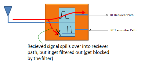
Figure 6. With a duplexer, the transmit filter blocks the receive frequency.
One label in Figure 6 needs a correction. The text under the duplexer says that the received signal spills over into the reciever path. The dashed arrow in the drawing goes toward the RF Transmiter Path, and the paragraph above it describes the same case, so the label should read transmitter path.
The transmit filter has a second job that the drawings do not show. A power amplifier produces broadband noise, and part of that noise falls in the receive band. The receive filter cannot remove it, because it sits at the receive frequency. Only the transmit filter can attenuate it, before it reaches the antenna port. So a duplexer needs rejection in both directions: the receive filter against the transmit frequency, and the transmit filter against the receive frequency.
Transmit leakage is the dangerous direction : a 23 dBm signal against 55 dB of rejection still reaches the receiver at about -32 dBm.The receiver works far below that level : the band 2 reference sensitivity at 10 MHz is -95 dBm.Each filter protects the other path : the receive filter rejects the transmit signal, and the transmit filter rejects amplifier noise in the receive band.One label in Figure 6 is wrong : the received signal spills over into the transmitter path, not the reciever path.
Types of Duplexers
Duplexers differ mostly in two ways: how much power they must handle, and how much loss they may add. Both depend on the filter technology inside, so the size of a duplexer tells you a lot about where it is used.
Like filters, you would see wide varieties of Duplexers. You would see very small sized duplexer like (a), (b), (c) which are usually SAW, BAW, FBAR based if you break open a mobile device like your mobile phone which is normally handling not that high power.
If you look into a system which are bigger than the mobile device and handling a relatively high power, you would see the deplexers like (d),(e),(f) which are directly designed on PCB or based on cavity filters.
In some applications handling extremly high power or requires very low insertion loss, you would see those duplexers like (g),(h),(i).

Figure 7. Duplexers grow with power. Surface mount packages serve handsets, boxed and machined designs serve base stations, and large cavity resonators serve high power sites.
(a), (b) and (c) are surface mount packages : they are small packages with solder pads underneath. These are the SAW, BAW and FBAR duplexers of a mobile phone.(d) and (e) are connectorized boxes : each has three coaxial connectors, one for the antenna and one each for the transmitter and the receiver.(f) is a machined block with many tuning screws : each screw tunes one cavity resonator of the filters inside.(g), (h) and (i) are cavity duplexers built from large resonator cans : the rods on top adjust the resonators. Their size gives very low loss and high power handling.
Ideal vs Real Duplexers
In terms of structure, Duplexer is just a complex of two filters. So the characteristics of duplexer is based on characteristics of filters. In most of mobile communication, the gap between the transmission frequency and reciever frequency is not that wide. So one of the critical requirement of duplexer would be how sharply separate the reciever frequency and transmitter frequency sitting right next to each other. The ideal requirement is to have very sharp separation without any overlapping but in reality you cannot avoid a certain degree of overlapping.
The picture below compares the ideal response on the left with two measured responses on the right. In each plot, the red curve is one filter and the blue curve is the other, and the vertical axis shows the loss from the antenna port to that filter's port.

Figure 8. Ideal and real duplexer responses. The real filters have a finite slope, some passband loss and a finite rejection, and the 20 MHz gap between the two passbands has to hold the whole transition.
Let's read the top plot. The red passband runs from about 1850 MHz to 1910 MHz, and the blue passband from about 1930 MHz to about 2000 MHz. This fits band 2, whose uplink is 1850 MHz - 1910 MHz and whose downlink is 1930 MHz - 1990 MHz. In their passbands both curves sit about 1 dB to 2 dB below 0 dB, which is the insertion loss. Outside its passband, the red curve stays around -45 dB to -50 dB across the blue band, and the blue curve stays around -55 dB across the red band.
The hard part is the gap. Band 2 leaves only 1930 - 1910 = 20 MHz between the two bands, about 1% of the carrier frequency. Each filter must fall from its passband to about -45 dB inside that gap, which is why the red curve drops almost vertically near 1920 MHz. Compare this with band 1, where the uplink ends at 1980 MHz and the downlink starts at 2110 MHz. That leaves a 130 MHz gap, so a band 1 duplexer can use much gentler slopes.
The passband loss has a cost on both sides. On the transmit side, 1 dB of loss means that 21% of the amplifier power turns into heat in the duplexer. On the receive side, the duplexer sits in front of the LNA, so its loss adds directly to the noise figure of the receiver. A duplexer design is therefore always a trade between a steep slope, which needs more resonators, and a low passband loss, which needs fewer.
A real passband has loss : about 1 dB to 2 dB in the measured plots, which costs transmit power and receiver noise figure.A real stopband has finite rejection : about -45 dB to -55 dB here, which sets how much transmit signal reaches the receiver.The duplex gap sets the difficulty : 20 MHz in band 2 against 130 MHz in band 1.Steep slopes and low loss pull against each other : more resonators give a steeper slope, but every resonator adds loss.