Balanced signal is a concept that does not apply to a single signal line. It is a concept that apply to a pair of signal lines. Balanced Signal means one original signal and one mirror image of the original signal running along a pair of signal lines as illustrated below. The conventional type of signal i.e the signal running along a single signal line is called Single-Ended signal (unbalanced signal).
In the diagram below, a device has a balanced port on each side. The + line and the - line of the left port carry a small signal and its mirror image. The right port carries a larger pair in the same way. Each line is drawn against its own reference, so the mirror relation is easy to see.
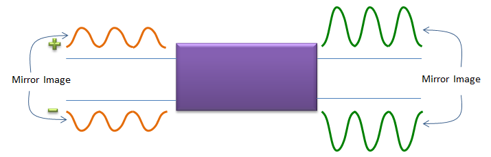
Figure 1. A balanced port carries a signal on a pair of lines. The two lines carry equal amplitudes with opposite polarity.
This page first defines how the two lines of a pair are described. Then it walks through the advantages of a balanced signal with the diagrams. It ends with the main drawback, which is the sensitivity to a phase offset between the two lines.
How are the two lines of a balanced pair described ?
Before comparing balanced and single-ended signals, we need names for what the two lines carry. Any pair of line voltages V+ and V- can be split into two parts. The differential mode voltage is Vd = V+ - V-. The common mode voltage is Vc = (V+ + V-)/2, the average of the two lines.
A perfectly balanced signal has V- = -V+. So Vc is zero and Vd is 2V+. Noise picked up equally by both lines changes only Vc. The receiver reads only Vd, so it ignores that noise. The flip and sum in the diagrams below does exactly this: flipping V- and adding it to V+ gives V+ - V-.
Quantity |
Definition |
Perfectly balanced signal |
Noise picked up equally by both lines |
Differential mode |
V+ - V- |
2V+ |
no change |
Common mode |
(V+ + V-)/2 |
0 |
equal to the noise |
A balanced receiver reads the difference : it responds to Vd and rejects Vc. How well it rejects Vc is called its common mode rejection.The impedance of a balanced port is quoted between the two lines : two uncoupled 50 ohm lines form a 100 ohm differential pair. That is why 100 ohm differential appears so often.A balun connects the two worlds : a balun converts between a balanced port and a single-ended, unbalanced port. Network analyzers describe balanced devices with mixed mode S-parameters. For example, Sdd21 is the differential path, and Scd21 is the conversion from differential to common mode.
Why Balanced Signal ?
Whenever any new technology comes out (especially in engineering field), we would ask why we need the new technology. You might have the same question for Balanced signal. Why we need, why we use the balanced signal ?
There are several well-known advantage of Balanced Signal.
First advantage is that with the balalanced signal combined it can enjoy the effect of doubling the amplitude of the received signal as illustrated below. As you know, the larger amplitude you have at the reciever side, the easier you can detect the signal. Due to this property, most of RF path operating at very low power or most of high speed digital line with very low driving voltage uses balanced signal.

Figure 2. The receiver sees the full swing between the two lines. That swing is twice the swing of one line, which is 6 dB more signal voltage.
The second advantage is that balanced signal shows high resistance to external noise. Let's suppose a noise is injected to a balanced signal. Since the same amount (same polarity, same amplitude) of noise (like (B)) is added to both the oroginal signal and mirror image of the signal, the shape of the noised signal becomes as (C). Then, when the mirror imaged signal gets flipped over at the reciever, the direction of noise signal become opposite between the two signal as shown in (D). If you sum up these two copies of the signal, you would get the amplified signal with the noise removed as shown in (E).
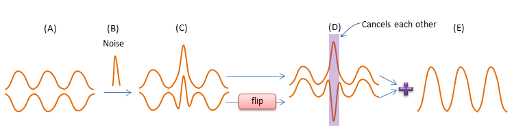
Figure 3. Noise that reaches both lines with the same polarity cancels at the receiver, while the signal adds up.
A and B : the clean balanced pair and a noise pulse.C : the noise pulse appears on both lines with the same polarity.D : after the flip, the two signal copies line up, and the two noise copies point in opposite directions.E : the sum doubles the signal and removes the noise.
Another advantage is that the balanced signal is highly resistant to the noise applied to the ground line (ground plane). By the nature of ground line, the noise on the ground line is interpreted as the noise with the same polarity and same amplitude on signal line as shown in (A). Any noise with the same polarity and same amplitude applied to both lines on the balanced signal lines get removed at the reciever when the mirror imaged signal get flipped and summed up with the original copy as shown in (B) and (C).
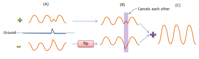
Figure 4. Noise on the ground line reaches both lines as common mode noise, so it cancels in the same way.
Both noise cases are the same case in the terms of the first section. External noise and ground noise add the same voltage to V+ and to V-. So they change Vc and leave Vd alone. The same argument explains a third benefit, which works in the other direction. The two lines of a balanced pair carry opposite currents, so their fields largely cancel at a distance. A balanced line therefore radiates less than a single-ended line with the same swing.
Twice the swing : the differential voltage is twice the swing of one line, so a low supply voltage still gives a usable signal.Common mode noise cancels : noise that reaches both lines equally, from outside or from the ground, is rejected by the receiver.Less radiation : opposite currents on two close lines produce fields that largely cancel.
Any Drawbacks ?
There are no technology that has advantagies only (of course, there is no technology that has drawbacks only). So balanced signal has its own drawbacks. The most common/serious drawback is that it is very vulnerable to phase offset between the two copies of the signal. Actually this kind of phase offset can break the main principle of balanced signal. Let's suppose some phase offset was introduced while the signal is traveling along the line as shown in (C). When this pair of signal is reiceved by the reciever and the mirror imaged signal gets flipped over, the noise cannot cancel out since it is position is different and the amplitude of the main signal gets smaller than the perfectly balaced signal.
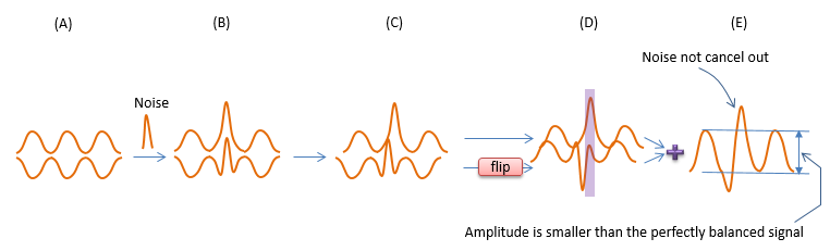
Figure 5. A phase offset between the two lines breaks the cancellation. The noise pulses no longer line up, and the summed signal is smaller.
Due to this vulnerability to phase offset, it requires very strict matching criteria if it is RF component or trace line and it requires very strict design rule if it is digital circuit.
Let's put numbers on both effects. Suppose one line has a phase offset of φ against the other. The flip and sum then gives an amplitude of 2cos(φ/2) instead of 2. The table below shows the loss for a few offsets. It stays small until the offset becomes large, so the loss of signal is the smaller of the two problems.
Phase offset |
Summed amplitude |
Loss against a perfect pair |
10 deg |
1.99 |
0.03 dB |
30 deg |
1.93 |
0.3 dB |
60 deg |
1.73 |
1.25 dB |
90 deg |
1.41 |
3.0 dB |
180 deg |
0 |
no signal |
The noise is the bigger problem. A timing skew τ between the lines turns into a phase offset of 360fτ deg at frequency f. Common mode noise at that frequency then leaves a residual of 2|sin(πfτ)| times the noise on one line. For a skew of 10 ps, the residual is -24 dB at 1 GHz. At 10 GHz it is only -4.2 dB, so almost none of the noise cancels. A skew of 1 ps brings the 1 GHz residual down to -44 dB.
The signal is forgiving, the noise rejection is not : 30 deg of offset costs only 0.3 dB of signal. The same offset leaves about half of the common mode noise.Skew matters more as frequency rises : the same 10 ps skew is 3.6 deg at 1 GHz and 36 deg at 10 GHz.Amplitude mismatch has the same effect : suppose one line has 10 percent more gain than the other. Common mode noise then leaves a residual of 0.1 times the noise on one line, or -20 dB, even with perfect timing.This is why the two lines are matched in length : differential pairs are routed with equal lengths and kept close together. RF baluns are specified for amplitude and phase balance.