PIM stands for Passive InterModulation Distortion(IMD). As it stands for, it is 'InterModulation' caused by 'Passive component'. A connector, a cable or an antenna can create it, even though none of them contains a transistor. PIM matters most where a strong transmitter and a sensitive receiver share one antenna path, as they do at a cellular base station.
InterModulation means 'mixing of two or more signals and generating other frequences which is different from original input frequencies'. It is same as the operation of a Mixer. The difference is that in case of Mixer the intermodulated signal is the one we want to get, but when we have such a mixed signal when we don't want it is normally callled 'Intermodulation Distortion (IMD)'.
With this in mind, we can take 'PIM' is a kind of IMD caused by 'Passive components'.
- What do you mean by 'Passive components' here ?
- Why PIM become problems ?
- How to measure PIM ?
- Reference
What do you mean by 'Passive components' here ?
You may think of filter, duplexer kind of things... yes... these are passive components. But the 'passive components' we talking about here has wider meaning. Any portion/parts which is not active in a system can be 'passive components'. Some examples of passive components which would be usual suspect of PIM are as follows.
- Coaxial connectors
- Feeder lines
- Any Joints where dissimilar metals meet
- Dirty connections
- Loose Connections
- Ferromagnetic metals
- Spark Discharges
Most items on this list have one thing in common. The RF current has to cross a junction, and that junction does not behave like a perfect resistor. A metal to metal contact, a thin oxide layer on it, or a ferromagnetic plating makes the current depend slightly on the voltage in a nonlinear way. Any nonlinear curve mixes the signals that pass through it, so every such junction becomes a very weak mixer.
Coaxial connectors are often the dominant source in a network, and reference [1] measured them in a two-tone test. The physical cause of PIM in a connector is still not fully known. But the measurements show clear trends, and they explain why the list above names materials and connections rather than component types.
- Each connection acts as a point source of PIM, most likely at the metal to metal junction between the mating parts.
- Different connector families produce PIM levels that differ by tens of dB. Larger connectors generally produce less PIM than smaller ones, for example N-type against SMA with the same metals.
- The metal matters as much as the size. Silver-plated N-type connectors produced at least 30 dB less PIM than "standard" N-type connectors with a nickel or stainless steel outer contact, although the geometry was the same. DIN 7-16 connectors stayed below the residual PIM of the test system.
- A loose connector varied by about 40 dB over time. The same connector, tightened to the correct torque, gave a constant level.
Any nonlinear junction in the RF path can create PIM : the source does not need to be an active device.Material and tightness matter most : nickel or stainless contacts and loose joints raise PIM, and silver plating and correct torque lower it.Large low-PIM connectors are used on high-power paths : a DIN 7-16 connector produced less PIM than the test system could measure.
Why PIM become problems ?
Usually PIM is very low power. usually lower than -100 dBc. Then why this kind of weak signal become a problem ? The answer comes from two facts together. The receiver is far more sensitive than the transmitter is strong, and some of the mixing products land exactly in the receive band.
It normally does not cause much issues when there is not much differences between transmitter power and reciever power because PIM power is very low comparing to these power. But it can be problem when the transmitter power is very high comparing to reciever power as in Cellular Base Station and Sattellite transmitter. In case of Cellular Base Station, for example, the trasmitter power from base station antenna is very high but the signal from mobile device coming into the base station recieiver antenna is extremely low comparing to the transmitter power. If any component in and around the transmitter path cause PIM, it would not be negligeably small comparing to the received signal. It would interfere with the weak recieved signal and causing poor communication quality.
Let's put numbers on it. Take a carrier of 43 dBm, which is 20 W, and a PIM product 150 dB below it. The PIM product then sits at -107 dBm. The thermal noise in one 180 kHz LTE resource block is -174 dBm/Hz + 10 log10(180000), which is -121.4 dBm. So this very small PIM product is still about 14 dB above the thermal noise that the uplink receiver works against. Reference [1] likewise notes that PIM levels as low as -115 dBm can cause interference in many systems.
The frequency of each product decides whether it hurts. Two carriers at f1 and f2 create third order products at 2f1 - f2 and 2f2 - f1, and fifth order products at 3f1 - 2f2 and 3f2 - 2f1. The table below uses LTE Band 3 as an example. In 36.101 v20.0.0 Table 5.5-1, Band 3 has its uplink at 1710 - 1785 MHz and its downlink at 1805 - 1880 MHz. Let the base station transmit two carriers at 1810 MHz and 1870 MHz.
Product | Frequency | Inside the Band 3 uplink ? |
2f1 - f2 = 2 x 1810 - 1870 | 1750 MHz | Yes |
2f2 - f1 = 2 x 1870 - 1810 | 1930 MHz | No |
3f1 - 2f2 = 3 x 1810 - 2 x 1870 | 1690 MHz | No, 20 MHz below the band edge |
3f2 - 2f1 = 3 x 1870 - 2 x 1810 | 1990 MHz | No |
The 1750 MHz product falls in the middle of the uplink band. A duplexer cannot remove it, because the PIM is created after the duplexer, in the feeder, the connectors or the antenna. From there it travels back to the receiver in the receive band, where the duplexer passes it by design. This is why PIM is so hard to filter out, and why reference [1] calls it often the dominant source of nonlinear distortion in high-power systems.
PIM also does not follow the usual rule for third order products. In an amplifier, the third order product usually grows by 3 dB for every 1 dB increase of the carrier power. Reference [1] measured a slope below 3 dB/dB for connectors, and the slope was not constant over the power range. So a PIM level measured at one power cannot simply be scaled to another power with the 3 dB/dB rule.
A tiny ratio becomes a large interferer : a product 150 dB below a 43 dBm carrier is still about 14 dB above the thermal noise of one LTE resource block.The frequency plan decides the damage : only the products that fall into the receive band matter, and 2f1 - f2 often does.Filtering does not help : the PIM is created after the duplexer and arrives at the receiver inside its passband.PIM does not scale at 3 dB/dB : measure it at the power the site actually uses.
How to measure PIM ?
Following is the conceptual design for PIM measurement. It is from reference [1] and I just put the comments on top of it. The difficulty is that the test system must create two strong tones and then detect a product more than 100 dB weaker, without adding PIM of its own.
The diagram below shows the whole chain. Two tone generators and two amplifiers feed a combiner, a duplexer sends the combined tones to the DUT, and a receiver listens on the Rx side of the same duplexer.
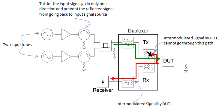
Conceptual PIM test system. The Tx filter passes the two tones to the DUT, and the Rx filter passes only the reverse PIM product to the receiver.
- The note at the left marks the two input tones. Each tone passes through its own amplifier.
- The note at the top points at the circulator with a load after each amplifier. It lets the signal go in only one direction and stops reflected power from going back into the source.
- The green arrow shows the two tones passing through the Tx filter of the Duplexer to the DUT. The DUT is terminated in a load.
- The red arrow shows the intermodulated signal from the DUT. It returns through the Rx filter to the Receiver. The note at the right says it cannot go back through the Tx path, and a black cross marks this.
Following can be more realistic illustration of the measurement system.
The diagram below replaces the tone sources and the receiver with real instruments. The rest of the chain is the same as in the diagram above.
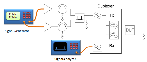
A practical PIM setup. One signal generator produces both tones, and a signal analyzer on the Rx port shows the PIM product as a spectral line.
- The Signal Generator display shows two frequencies, F1 Mhz and F2 Mhz, on two outputs.
- The Signal Analyzer is connected to the Rx filter of the Duplexer. Its screen shows a few spectral lines.
- The amplifiers, the circulators with loads, the combiner, the Duplexer and the terminated DUT are the same as in the conceptual diagram.
The measurements in reference [1] used a commercial PIM analyzer built this way. The two carrier tones were at 463 MHz and 468 MHz, and the third order product 2f1 - f2 was measured at 458 MHz. The receiver measured the product that travels back towards the duplexer, which is called reverse PIM. Forward PIM travels on towards the load.
The test system sets its own limit. The amplifiers and circulators are kept on the far side of the duplexer, so their distortion is filtered out. But the cables, the connectors, the dummy load and the filter itself still create some PIM. This residual PIM of the system adds to the PIM of the DUT and sets the lowest level that can be measured. The DIN 7-16 result above is an example. Those connectors were below the residual level, so only an upper bound could be reported.
Several PIM sources in one DUT add with different phases in the reverse direction, because each source sits at a different distance from the receiver. So two sources can partly cancel each other. In a test network in reference [1], the PIM of a BNC connector interfered destructively with the PIM of an SMA connector. At higher power the network produced less PIM than the SMA connector would produce on its own. So a low reading on a site does not prove that every connection is good.
A PIM test is a two-tone test through a duplexer : the Tx filter feeds the tones to the DUT, and the Rx filter passes only the product.The test system has its own PIM floor : low-PIM cables, connectors and loads are needed to measure a low-PIM DUT.Reverse PIM from several sources can cancel : the total depends on the spacing between the sources, not only on their levels.
Reference
[1] Justin Henrie et al, Prediction of Passive Intermodulation From Coaxial Connectors in Microwave Networks
IEEE TRANSACTIONS ON MICROWAVE THEORY AND TECHNIQUES, VOL. 56, NO. 1, JANUARY 2008
[2] 3GPP TS 36.101 V20.0.0 : E-UTRA User Equipment radio transmission and reception, Table 5.5-1