What is Power Density ? As it name implies.. it is "Density of Power"? So simple ? -:) In RF work the answer is almost that simple. Power density tells how much RF power flows through each square metre at one point in space. It links the power of a transmitter to what a receiver, or a person, at that point actually gets.
You may vaguely understand what 'Power' is even though you may not be able to describe it clearly and you may vaguely understand what 'Density' means. All of these came from what you learned in high school physics class.
- What does power density mean for RF ?
- How fast does power density fall with distance ?
- How does the antenna pattern change power density ?
- How does power density turn into received power ?
What does power density mean for RF ?
Let's build the definition from its two words, and then fix the unit. The unit is the part that matters most in RF, because the word density can mean per volume or per area.
Power indicates the rate over energy transfer over a certain time.
Density indicates 'something measured (or contained) per unit volume (or per unit surface)'.
Just combining these two definition, you can get the definition of Power Density. Power Density is 'Power per unit area'. and it would indicate 'how much energy transfer happens over a specific time through a predefined unit area'.
Over the course and your experience, you might have seen many different form of 'Power', such as mechanical power, electrical power etc.
Since this page is about RF, the Power in this context is most likely mean 'the rate of RF energy transfer over a certain period'. If we confine this to more specific application, like Antenna, the power can mean 'Transmitter Power (energy over a certain time period) from an antenna'.
For a radio wave, the power flows through a surface, so RF power density is measured per unit area. The SI unit is W/m2. RF exposure work often uses mW/cm2 instead, and 1 mW/cm2 equals 10 W/m2. Power per unit volume is a different quantity. It appears in other fields, for example in the power density of a battery in W per litre, and it is not what an RF engineer means.
In the far field of an antenna, the power density S and the electric field strength E are linked. The link is the impedance of free space, η0 = 120π, which is about 377 ohm. The relation is S = E2/η0, with E as an RMS value in V/m. So a power density of 1 W/m2 corresponds to a field strength of 19.4 V/m. Many measurement probes read V/m, and this relation converts their reading into W/m2.
RF power density is power per unit area : the unit is W/m2, or mW/cm2 in exposure work.Power density and field strength are two views of one wave : in the far field S = E2/377 ohm.
How fast does power density fall with distance ?
A transmitter sends out a fixed power, but that power spreads over a larger surface as it travels. The simplest case, an isotropic source, shows the rule that every other case builds on.
An isotropic source radiates the same power in every direction. At a distance r, its power Pt is spread evenly over the surface of a sphere with area 4πr2. So the power density is
S = Pt / (4πr2)
The table below applies this formula to a 1 W isotropic source.
Distance r | Sphere area 4πr2 | Power density S |
1 m | 12.57 m2 | 79.6 mW/m2 |
10 m | 1257 m2 | 0.796 mW/m2 |
100 m | 125664 m2 | 7.96 microwatts/m2 |
Each step of ten times the distance lowers the power density by a factor of 100, which is 20 dB. This is the inverse square law. Nothing is absorbed in this calculation. The power is only spread more thinly, and the total over the whole sphere is still 1 W at every distance.
The formula holds in the far field of the antenna. Close to the antenna, the field has reactive parts that do not carry power away, and S = E2/377 ohm no longer holds there. So a power density measured very close to an antenna has to be treated with care.
Power density falls with the square of the distance : ten times the distance gives 20 dB less power density.The total power does not change with distance : it is only spread over a larger sphere.The simple formula is a far-field formula : near the antenna the power density needs a different treatment.
How does the antenna pattern change power density ?
A real antenna is never isotropic. It sends more power in some directions and less in others, so two points at the same distance can see very different power densities.
For example, let's suppose we have two antenna showing the propagation pattern as shown below. You picked the three locations for power density measurement. In left pattern (omni directional antenna), the power density is same all over the place. In right pattern, the power density gets different depending on which point you pick. As seen in this example, Power density can be a good indicator when you comparing the energry transfer rate (Transmitted power in case of Antenna) among multiple different locations.
The picture below draws two antennas side by side. Each one sits in the middle of a circle, and three measurement points sit on that circle at the same distance from the antenna.
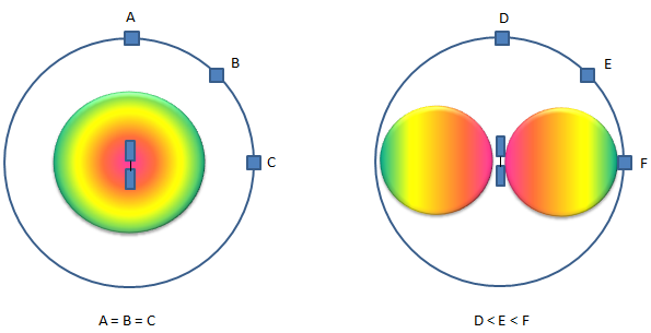
Equal distance does not mean equal power density. The pattern of the antenna decides how the power is shared between directions.
- On the left, the pattern is drawn as a round ball around the antenna. The points A, B and C lie on the circle, and the label says A = B = C.
- On the right, the pattern has two lobes, one on each side of a vertical dipole. Point D sits above the antenna, E sits at an angle and F sits at the side. The label says D < E < F.
- The colours run from red near the antenna to green at the edge of each lobe. The lobe is widest at the side, where F is, and it narrows to nothing towards the top, where D is.
The left pattern needs one comment. A pattern that is the same in every direction is an isotropic radiator. It is a reference model, not a real antenna. A real omnidirectional antenna, such as a vertical dipole, is uniform only in the horizontal plane. It has a null along its own axis, exactly like the right pattern in the picture. So the left drawing shows the isotropic reference, and the right drawing shows what a practical omnidirectional antenna does.
The antenna gain G tells how much stronger the power density is in a direction than it would be with an isotropic antenna. So the formula of the previous section becomes S = Pt x G / (4πr2). The product Pt x G is the EIRP. For example, a base station with 43 dBm of power and 17 dBi of antenna gain has an EIRP of 60 dBm, which is 1000 W. At 100 m in the main beam, the power density is 1000 / (4π x 1002) = 7.96 mW/m2. The field strength is then about 1.73 V/m.
The pattern shares the power between directions : at the same distance, the power density follows the shape of the pattern.An omnidirectional antenna is not isotropic : a vertical dipole has a null along its axis, as at point D.Use EIRP in the power density formula : S = EIRP / (4πr2) in the direction the gain was given for.
How does power density turn into received power ?
A receiving antenna does not collect the power density itself. It collects the power that flows through a certain area, and that area connects power density to the usual link budget.
This area is the effective aperture Ae of the receiving antenna. The received power is Pr = S x Ae. The effective aperture depends on the gain and the wavelength, Ae = Gr x λ2/(4π). An isotropic antenna at 2 GHz, with λ = 0.15 m, has Ae = 0.00179 m2, or about 18 cm2.
Let's continue the base station example. The power density at 100 m is 7.96 mW/m2. An isotropic receiving antenna at 2 GHz then collects 7.96 mW/m2 x 0.00179 m2 = 14.2 microwatts, which is -18.5 dBm. The free space path loss over 100 m at 2 GHz is 20 log10(4πr/λ) = 78.5 dB, and 60 dBm - 78.5 dB gives the same -18.5 dBm. So the Friis formula is the power density formula and the effective aperture put together.
The effective aperture also explains a point that often confuses people. The power density at a given distance does not depend on the frequency. But the aperture of an antenna with a fixed gain shrinks with λ2. So at a higher frequency, the same gain collects less power, and this is where the frequency term of the free space path loss comes from.
Received power is power density times effective aperture : Pr = S x Ae, with Ae = Gr x λ2/(4π).The Friis formula follows from this : 60 dBm EIRP at 100 m and 2 GHz gives -18.5 dBm by both routes.The frequency term belongs to the receiving antenna : the power density does not depend on frequency, but the aperture of a fixed-gain antenna does.