If you wants to have just overview of LTE, this section would not help you much, but if you are interested in protocol stack development or test case development these may be good tips. In many cases in this area, you will notice that a seemingly simple concept will turn out to be very complicated in terms of implementation. Just try to have overall idea on multiple parameters and their dependencies for a specific feature.
- RB Size allocation for each System Bandwidth
- Resource Allocation Type Table
- Throughput Calculation Example
- Meaning of UL Signal Analysis Parameter parameters
- Code Rate
- Units for Resource Allocation and Management
- PDCCH Resource Allocation
- PDCCH Candidate and Search Space
- Calculating CCE Index
- DCI(Downlink Control Information)
- GUTI(Globaly Unique Temporary ID)
RB Size allocation for each System Bandwidth
For Resource Allocation Type 0 which is the most common resource allocation type, there is a rules for DL_RB setting
if System BW = 1.4 M, it should be multiples of 1 (1 x n)
if System BW = 3 M, it is should be multiples of 2 (2 x n)
if System BW = 5 M, it should be multiples of 2 (2 x n)
if System BW = 10 M,it should be multiples of 3 (3 x n)
if System BW = 15 M, it should be multiples of 4 (4 x n)
if System BW = 20 M, it should be multiples of 4 (4 x n)
This rule is derived from the Resource Block Group(RBG) size for each bandwidth, and the RBG size for system bandwidth is shown in TS 36.213 Table 7.1.6.1-1. (Number of DL RB should should be the multiples of RBG for the corresponding system bandwidth)
* Reference for additional restriction and details :
TS 36.104 Table 5.2.1 for DL (Number of RBs for each System BW),
TS 36.211 Section 5.3.3 for UL (UL_RB = 2^a x 3^b x 5^c)
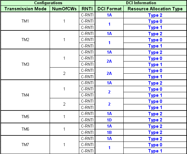
Resource Allocation Type Table
Determining a Resource Allocation type is very tricky since many other parameters get involved. One informative table would help you with this job.
Throughput Calculation Example
If you know the MCS index, you can calculate the throughput for that specific MCS idex as follows:
Calculation Procedure for downlink(PDSCH) is as follows :
i) refer to TS36.213 Table 7.1.7.1-1
ii) get I_TBS for using MCS value (ex, I_TBS is 21 if MCS is 23)
iii) refer to TS36.213 Table7.1.7.2.1
iv) go to column header indicating the number of RB
v) go to row header �21� which is I_TBS
vi) you would get 51024 (if the number of RB is 100 and I_TBS is 21)
vii) (This is Transfer Block Size per 1 ms for one Antenna)
If we use 2 antenna, it is 51024 bits * 2 Antenna * 1000 ms = about 100 Mbps
Calculation Procedure for uplink(PUSCH) is as follows :
Same as the downlink as above except that you have to refer to 36.213 Table 8.6.1-1 at step i)
Uplink Analysis Paremeter Calculation
Click here for TS 36.213 Tables for TBS
Meaning of UL Signal Analysis Parameter parameters:
i) Sequence Group Number : This means "u" value described in TS36.211 v8.7.0 5.5.1.3 Group hopping ii) Base Sequence Number : This means "v" value described in TS36.211 v8.7.0 5.5.1.4 Sequence hopping
iii) Cyclic Shift Index : This means "n_cs" value described in TS36.211 v8.7.0 5.5.2.1.1 Reference signal sequence
Relationship between Items and parameters in C Scenario:
i) Sequence Group Number u = ( ( CellID % 30 ) + deltaSS ) % 30
CellID: Cell ID specified by parameter file(.pme)
deltaSS: LteCphyUlConfigUL_SCH.ULRSConfig.GroupAssignment
ii) Base Sequence Number Fixed to 0.
iii) Cyclic Shift Index n_cs = ( n1_DMRS + n2_DMRS + n_PRS(n_s) ) % 12
n1_DMRS: Calculated from CphyUlConfigUL_SCH.RSSoundConfig.Dedicated.CyclicShift
n2_DMRS: Fixed to 0.
n_PRS(n_s): Calculated from the following scenario parameters.( Please refer to above spec )
Code Rate
When you have unrestricted resource to allocate for a certain UE, it would be happy. Even when you develop call processing protocol sequence to test UE, there may be times when you want to allocate a bare minimum resource for a certain data traffic. Then the issue is how to figure out the bare minimum resource for the traffic. If you allocate the resource less than the minimum value, the data would not get trasmitted or would not get decoded even though it got transmitted.
For this there is a guideline in 3GPP specification. TS36.213 7.1.7 Modulation order and transport block size determination and it says as follows.
The UE may skip decoding a transport block in an initial transmission if the effective channel code rate is higher than 0.930, where the effective channel code rate is defined as the number of downlink information bits (including CRC bits)divided by the number of physical channel bits on PDSCH. If the UE skips decoding, the physical layer indicates tohigher layer that the transport block is not successfully decoded. For the special subframe configurations 0 and 5 withnormal CP or configurations 0 and 4 with extended CP, shown in table 4.2-1 of TS 36.211: �Evolved Universal Terrestrial Radio Access (E-UTRA); Physical channels andmodulation�, there shall be no PDSCH transmissionin DwPTS of the special subframe.
Let's take an example with MCS = 8 and No of RBs = 3.
For this we have to get the two numbers based on specification quoted above.
(i) number of downlink information bits (including CRC bits )
(ii) number of physical channel bits
(i) refers to "(Transport Block Size + CRC bits)" which is the size of the message that gets channel coded.
(ii) refers to the number of available bits in the PHYSICAL LAYER. Each resource element(RE) can carry 2, 4, or 6 bits depending on the modulation scheme.We just have to count the number of REs reserved for PDSCH transmission on each subframe, and then multiply it by 2, 4, or 6 (accordint to modulation scheme) and then we will have the number of physical channel bits on PDSCH.
Getting back to our example condition MCS = 8 and No of RBs = 3. In this case,
for item (i), we can easily figure this out from TS36.213 Table7.1.7.1-1
for item (ii) we have
a) 3 x 12 REs/symbol
b) (14 symbols/subframe) x (3 x 12 REs/symbols) = 504 REs/subframe. Out of this 504 REs, we have to remove those REs allocated for PDCCH since it is not carrying the real data. Let's assume that 3 symbols/subframe are allocated for PDCCH. In this case, the number of REs for avaiable in PHY LAYER for data transmission is 504 - (3 x (3 x 12)) which is 396. Now we have to convert this number into "number of bits". In our sample case, the modulation scheme is QPSK which carries 2 bits per RE. Therefore, the value for item (ii) is 2 x 396 = 792. This assumes that the subframe does not carry PBCH, PSS, SSS. If it is the subframe that carries these signals, we have to remove the REs for PBCH, PSS, SSS as well.
Now we have the value (i) and (ii). If you take (i)/(ii), you will get the Code Rate.
I admit the explanation above would sound too complicated and messy. I asked on this to another expert on this area and he gave me much clearer explanation as follows :
The code rate is the result (consequence) of the combination of TBS, MCS, and N_RB we have chosen for the transmission. Effective channel code rate is defined as the number of downlink information bits (including CRC bits) divided by the number of physical channel bits on PDSCH
Let us take the caseMCS=8; ITBS=8, TBS=808; N_PRB=6
The number of downlink information bits =808+24 (CRC bits) = 832The number of physical channel bits on PDSCH = 6 (N_PRB)*12(no. of subcarriers in a PRB)*7(number of OFDM symbols in a slot)*2(no. of slots in a subframe)*2(number of bits per modulated symbols)=2016
Effective channel code rate = 832/2016 = 0.4127
Basically, the encoder is a fixed 1/3 code. The rate matching unit takes out different number of coded bits before transmission in the channel
Units for Resource Allocation and Management
Reading various LTE specification, you will see many terms which seems to be related to resource allocation but looks very confusing. At least you have to clearly understand the following units.
i) Resource Element(RE) : The smallest unit made up of 1 symbol x 1 subcarrier.
ii) Resource Element Group (REG) : a group of 4 consecutive resource elements. (resource elements for reference signal is not included in REG)
iii) Control Channel Element (CCE) : a group of 9 consective REG
PDCCH Resource Allocation
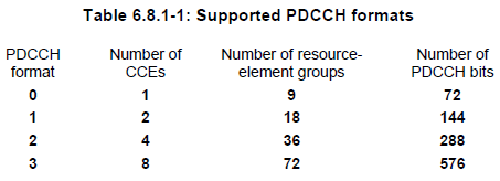
One PDCCH is carried by multiple number of consecutive CCEs. How many CCEs are necessary to carry one PDCCH ? It depends on the format of the PDCCH. The relationship between PDCCH format and the number CCE required to carry the PDCCH is as follows :
PDCCH Format 0 : Requires 1 CCE = Aggregation Level 1
PDCCH Format 1 : Requires 2 CCE = Aggregation Level 2
PDCCH Format 2 : Requires 4 CCE = Aggregation Level 4
PDCCH Format 3 : Requires 8 CCE = Aggregation Level 8
The number of consecutive CCEs required to carry one PDCCH is called "Aggregation Level'. TS 36.211 Table 6.8.1.1 shows these relations.
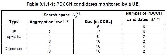
PDCCH Candidate and Search Space
In the PDCCH region in DL radio frame, there can be many places where a specific PDCCH is located and UE searches all the possible locations. The possible location for a PDCCH differs depending on whether the PDCCH is UE-Specific or Common, and also depend on what aggregation level is used. All the possible location for PDCCH is called 'Search Space and each of the possible location is called 'PDCCH Candidates'.
A table from 36.213 shows these relationship as below.
Calculating CCE Index
CCE Index is the CCE number at which the control channel data is allocated. Normally this index changes for each subframe, meaning that the control channel data allocated in each subframe changes subframe by subframe.
One of the most common situations where you have to care about this CCE index is when you change the system BW. Changing the system bandwidth in higher layer (L3) is very simple. You only have to change one IE in MIB, but if you are a protocol stack developer or test case developer who take care of all stack from L1 through L3, you have to calculate CCE index for each subframe and those index gets different for each bandwidth. But calculating CCE is not a simple procedure. Just outline of the calculation is as follows. Just try to have an idea on which parameters you need and how they are related to calculate CCE.
i) Prepare REG Table
ii) Select the system BW(=BW)
iii) Get the max number of RB for the BW (=N_RB)
iv) Select the Number of HI Group (=No_HI_Group)
v) Set the REG using CFI (REG_CFI = 4)
vi) Select the CFI (=CFI)
vii) Get Ng (=Ng)
viii) Create CFI vs BW table using Ng, REG_CFI, No_HI_Group (=CFI_BW_Table)
ix) Create HI_Group vs. BW table using Ng,N_RB (=HI_Group_BW_Table)
x) Get the element from HI_Group_BW_Table where BW and Ng cross.(=HI_Group)
xi) Get the element from CFI_BW_Table where CFI and BW cross(=N_CCE)
xii) Select CRNTI
xiii) Specify A,D,Y-1,Lx
iv) Calcuate Y0~Y9 from A,N_CCE,D
xv) Specify Aggregation Level(=L, where L = {1,2,4,8})
xvi) Calculate CCE Index from L,Y0~Y9,N_CCE
For further details of the procedure, refer to TS 36.213 - 9.1.1 PDCCH Assignment Procedure
DCI(Downlink Control Information)
Refer to DCI sections.(Click Here)
GUTI(Globaly Unique Temporary ID)
As the name implies, GUTI is a kind of temporary ID. Each of the UE has a couple of different kind of it's own Unique ID like IMSI, IMEI etc, but to use these unique ID all the time during the communication would make the security vulnerable. So in some wireless communication, we use a temporary ID which maps the unique ID allocated to UE. And this temporary ID changes often, so even if somebody hacked out the ID it will be useless soon.
In WCDMA, you may remember that we had several commonly used IDs, IMSI, TMSI, P-TMSI. IMSI is a unique ID stored in USIM and permanent ID. TMSI, P-TMSI is a temporary ID which is mainly used as a replacement for IMSI.
GUTI is also a temporary ID and it is slimilar to P-TMSI in UMTS. The structure of GUTI is as follows :
- PLMN (3 Bytes)
- MME Group ID (2 Bytes)
- MME Code (1 Bytes)
- M-TMSI (4 Bytes)
+-GUTI ::= TLV OPTIONAL:Exist
| +-Octet1 ::= DIVISION
| | +-EPS mobile identity IEI ::= IEI [50]
| +-Octet2 ::= DIVISION
| | +-Length of EPS mobile identity contents ::= LEN (0..255) [11]
| +-Octet3 ::= DIVISION
| | +-Spare ::= FIX [F]
| | +-Odd/even indication ::= CHOICE [....]
| | +-Type of identity ::= CHOICE [GUTI]
| +-Octet4 ::= DIVISION
| | +-MCC digit 2 ::= INT (0..15) [0]
| | +-MCC digit 1 ::= INT (0..15) [0]
| +-Octet5 ::= DIVISION
| | +-MNC digit 3 ::= INT (0..15) [15]
| | +-MCC digit 3 ::= INT (0..15) [1]
| +-Octet6 ::= DIVISION
| | +-MNC digit 2 ::= INT (0..15) [1]
| | +-MNC digit 1 ::= INT (0..15) [0]
| +-Octet7 ::= DIVISION
| | +-MME Group ID ::= INT (0..255) [128]
| +-Octet8 ::= DIVISION
| | +-MME Group ID(continued) ::= INT (0..255) [1]
| +-Octet9 ::= DIVISION
| | +-MME Code ::= INT (0..255) [1]
| +-Octet10 ::= DIVISION
| | +-M-TMSI ::= INT (0..255) [0]
| +-Octet11 ::= DIVISION
| | +-M-TMSI(continued) ::= INT (0..255) [0]
| +-Octet12 ::= DIVISION
| | +-M-TMSI(continued) ::= INT (0..255) [0]
| +-Octet13 ::= DIVISION
| +-M-TMSI(continued) ::= INT (0..255) [1]
Examples of NAS messages using GUTI are
- Attach Request
- Attach Accept
- Attach Complete