802.11ad is a specially designed to work in extremely high frequency and with extremly wide bandwidth offering the high throughput relatively simple structure. What I mean by 'relatively simple structure' mean 'without using high degree of MIMO and high order modulation technique'. It doesn't really mean that 802.11ad is easy to implement. In terms implementation, we need to overcome various technical issues that should work at mmWave (60 Ghz) range. Overall characteristics (features) of 802.11ad can be summarized as in the following diagram.
The diagram below puts 802.11ad in a triangle at the centre and three features around it. Two of them are the goal and the drawback. The goal is High Throughput, around 7 Gbps. The drawback is Short Range, less than 10 m. The third feature, High Frequency around 60 Ghz, is the reason for both of them.
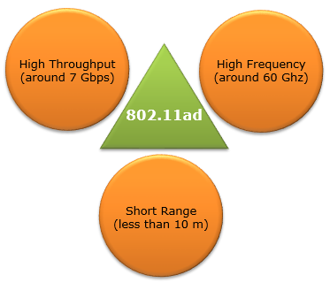
Figure 1. The three headline features of 802.11ad. The 60 GHz carrier gives the wide channel that makes the throughput possible, and it also causes the short range.
High Throughput : the rate comes from a very wide channel, not from MIMO or dense modulation. The next section works out the numbers.High Frequency : the 60 GHz band is unlicensed and has room for channels of 2.16 GHz each. The 57 to 71 GHz range holds six of them.Short Range : path loss is higher at 60 GHz, and the signal does not pass well through walls. So one 802.11ad link usually covers one room.
Why can 802.11ad reach Gbps without MIMO ?
In terms of throughput, you may see 802.11ad does not provide much higher throughput than 802.11ac. Actually theoretical max throughput of 802.11ac (8 stream, 256 QAM) is higher than 802.11ad. However, in regular / common operation, higher throughput would be more easily achieved with 802.11ad.
At least as of now (Jun 2017), 802.11ad does not support MIMO and does not support very high order modulation scheme (e.g, 256 QAM; only the OFDM PHY below goes up to 64 QAM). Then you may ask.. how can we achieve such a high throughput without using higher order modulation or high degree MIMO ? The answer is simple.. just use super-wide bandwidth :). A single channel 802.11ad bandwidth is up to 1.88 Ghz (almost 2 Ghz). This can be a big challenge in baseband implementation. (Of course, RF side challenge is to develop / implement 60 Ghz components.
Let's put numbers on this comparison. A PHY rate is the number of data subcarriers, times the bits per subcarrier, times the coding rate, times the number of streams, divided by the symbol duration. For the 802.11ac peak, a 160 MHz channel has 468 data subcarriers and a symbol of 3.6 microseconds with the short guard interval. With 256 QAM at rate 5/6, one stream gives 468 x 8 x 5/6 / 3.6 microseconds = 866.7 Mbps. Eight streams give 6.93 Gbps.
802.11ad reaches the same range in a different way. Its single carrier PHY sends 1.76 G symbols per second inside a 2.16 GHz channel. So even pi/2-BPSK at code rate 1/2 carries 1.76 x 1 x 1/2 = 0.88 Gbps before the guard interval overhead. That is about the peak of one 802.11ac stream, but with the most robust modulation. 16 QAM at rate 3/4 gives 1.76 x 4 x 3/4 = 5.28 Gbps, again before the guard interval overhead. The table below puts the two side by side.
Case |
Channel |
Modulation and code rate |
Streams |
Rate |
802.11ac, 1 stream | 160 MHz | 256 QAM, 5/6 | 1 | 866.7 Mbps |
802.11ac, 8 streams | 160 MHz | 256 QAM, 5/6 | 8 | 6.93 Gbps |
802.11ad SC, most robust data | 2.16 GHz | pi/2-BPSK, 1/2 | 1 | 0.88 Gbps, before GI |
802.11ad SC, 16 QAM | 2.16 GHz | 16 QAM, 3/4 | 1 | 5.28 Gbps, before GI |
The drawback of the 60 GHz carrier is path loss. Free space path loss grows with 20 log10 of the frequency, so at the same distance 60 GHz loses 20 log10(60/5) = 21.6 dB more than 5 GHz. At 10 m, that is 88.0 dB against 66.4 dB with isotropic antennas. The short wavelength also helps, though. It is 5 mm at 60 GHz, so a 4 x 4 array with half wavelength spacing is only about 1 cm wide. Such an array gives about 10 log10(16) = 12 dB of gain, and with an array at both ends the link recovers the 21.6 dB. This is why every 802.11ad PHY frame ends with a Beamforming Training field, as the next section shows.
Bandwidth replaces MIMO and dense modulation : a 2.16 GHz channel is 13.5 times wider than the widest 802.11ac channel.The peak rates are similar : 802.11ac needs eight streams to reach 6.93 Gbps, while 802.11ad gets to the same range with one stream.Beamforming is not optional at 60 GHz : antenna array gain at both ends makes up for the extra 21.6 dB of path loss.
PHY Frame
802.11ad defines four PHY types, and each one has its own frame. All four frames share the same skeleton. A Preamble made of STF and CEF comes first, then a Header, then Data, and finally an optional BFT field for beamforming training. So when you compare the frames below, look at two things: the modulation over each part, and the list of fields inside the Header.
Control PHY Frame
The Control PHY carries control messages only. It has to work before two devices have trained their beams toward each other, so it trades rate for robustness. The diagram below shows that one modulation, pi/2-DBPSK, covers the whole frame from STF to Data, and the header is short.
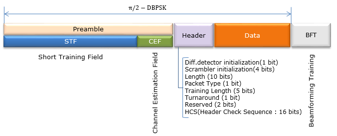
Figure 2. Control PHY frame. The whole frame uses differential BPSK, and the header holds only 40 bits.
pi/2-DBPSK over everything : differential detection works on the phase change from one symbol to the next, so the receiver does not need an accurate phase reference.Header fields : Diff.detector initialization 1, Scrambler initialization 4, Length 10, Packet Type 1, Training Length 5, Turnaround 1, Reserved 2 and HCS 16. They add up to 40 bits.No MCS field : the control mode has only one rate. In the MCS numbering of 802.11ad, MCS 0 identifies this control mode.BFT at the end : the Training Length field says how much beamforming training follows the data.
Single Carrier PHY Frame
The Single Carrier PHY is the one most devices use for data. Its preamble and header stay in pi/2-BPSK so that every receiver can decode them, and only the Data part changes modulation. The header in the diagram below is longer than the control header, because it now has to describe an MCS.
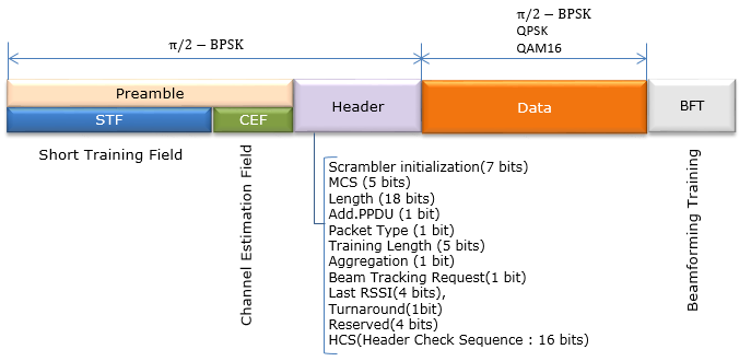
Figure 3. Single Carrier PHY frame. The header is 64 bits, and it signals the MCS that the Data part uses.
Data modulation : pi/2-BPSK, QPSK or 16QAM, chosen by the 5 bit MCS field.Header size : the fields as drawn add up to 7 + 5 + 18 + 1 + 1 + 5 + 1 + 1 + 4 + 1 + 4 + 16 = 64 bits.Length 18 bits : this field can hold values up to 262,143, against 1,023 for the 10 bit Length of the control header.Last RSSI and Beam Tracking Request : these fields let the two ends keep the beam and the link adaptation up to date during data transfer.
The data is protected by LDPC with a codeword of 672 bits. The pi/2 rotation in the name means that each symbol is rotated by 90 deg from the one before it. This keeps the signal away from the origin between symbols, so the power amplifier sees a lower peak-to-average ratio. That matters at 60 GHz, where output power is expensive.
Low Power Single Carrier PHY Frame
The Low Power Single Carrier PHY targets battery devices such as phones, with rates up to about 2.5 Gbps. Compare the diagram below with the Single Carrier one above. The preamble and the header are the same, and the only visible change is that the Data part stops at QPSK.
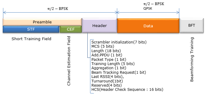
Figure 4. Low Power Single Carrier PHY frame. The frame looks like the Single Carrier frame, and the saving comes from a simpler Data part.
Same header : the field list is identical to the Single Carrier header, 64 bits in total.Data modulation : pi/2-BPSK or QPSK only, with no 16QAM.Where it fits : this is the lowest power mode of 802.11ad, aimed at mobile devices such as smartphones. The Single Carrier mode stays available for the highest rates.
OFDM PHY Frame
The OFDM PHY gives the highest modulation of 802.11ad, up to 64 QAM. But it keeps the single carrier preamble, as the diagram below shows. So a receiver first synchronizes in pi/2-BPSK, and it switches to OFDM only at the Header, which uses QPSK.
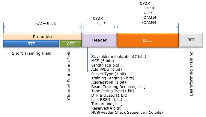
Figure 5. OFDM PHY frame. The preamble is shared with the single carrier modes, and the Header and Data are OFDM.
Data modulation : SQPSK, QPSK, QAM16 or QAM64. SQPSK is spread QPSK, the most robust OFDM option.Two new header fields : Tone Paring Type and DTP Indicator. Both are about tone pairing, an OFDM-only feature, so the single carrier headers do not carry them.Header size as drawn : the fields add up to 66 bits, 2 more than the single carrier header, because Reserved is still drawn as 4 bits.
The Reserved width in the OFDM header could not be checked against the standard, so treat the 66 bit total with care. The OFDM PHY is defined in the standard, but test equipment vendors have noted that it had no commercial implementation. In practice, 802.11ad products use the Control PHY and the Single Carrier PHY.
One skeleton, four PHYs : every frame is Preamble, Header, Data and BFT. The PHYs differ in modulation and header content.The preamble is always pi/2-BPSK or pi/2-DBPSK : a receiver can detect any 802.11ad frame before it knows which PHY sent it.Control PHY first, data PHY later : the robust control mode carries the frames that set up the beam, and the faster modes carry data once the beam exists.
Additional MAC Frame Types
In 802.11ad, Following new Frame Types are added to the existing type. The reason is the 2 bit Type field. Management, Control and Data used three of its four values, and 802.11ad needed new frames for beam training and scheduled access. So 802.11ad takes the last Type value, 11, for the Extension type, and it uses one Control subtype, 0110, to point to a further 4 bit field.
|
Type |
Type Description |
Sub Type |
Sub Type Description |
|
01 |
Control |
0000-0001 |
Reserved (This is changed from existing field) |
|
01 |
Control |
0110 |
Control Frame Extension |
|
11 |
Extension |
0000 |
DMG(Directional Multi Gigabit) Beacon |
|
11 |
Extension |
0001-1111 |
Reserved |
The DMG Beacon is the most visible result. It uses the Extension type, so a receiver that knows only the older types does not parse it as a beacon. Also, Extension subtype 0001 is no longer reserved today. The later 802.11ah amendment uses it for the S1G Beacon.
When Frame Extension type is configured, the structure of Frame Control field is defined as follows
The diagram below shows three levels of detail. The top row is the whole packet, and the middle row is the MAC Header. The bottom row is the 2 byte Frame Control field of a control frame with Type 01 and Sub type 0110.
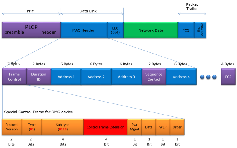
Figure 6. Frame Control of a DMG control frame extension. The 4 bit Control Frame Extension takes the place of the flag bits that follow Sub type in other frames.
Bit budget : Protocol Version 2, Type 2, Sub type 4, Control Frame Extension 4, then Pwr Mgmt, Data, WEP and Order at 1 bit each. The total is still 16 bits.What was given up : in other frames, those 4 bits hold To DS, From DS, More Fragments and Retry. A DMG control frame does not need them.Labels : Data here is the More Data bit, and WEP is the Protected Frame bit.
The Control Frame Extension bit field is defined as follows (802.11ad - Table 8-1aControl Frame Extension).
|
Type |
Sub Type |
Control Frame Extension |
Description |
|
01 |
0110 |
0000 |
Reserved |
|
01 |
0110 |
0001 |
Reserved |
|
01 |
0110 |
0010 |
Poll |
|
01 |
0110 |
0011 |
SPR |
|
01 |
0110 |
0100 |
Grant |
|
01 |
0110 |
0101 |
DMG CTS |
|
01 |
0110 |
0110 |
DMG DTS |
|
01 |
0110 |
0111 |
Grant ACK |
|
01 |
0110 |
1000 |
SSW |
|
01 |
0110 |
1001 |
SSW-Feedback |
|
01 |
0110 |
1010 |
SSW-Ack |
|
01 |
0110 |
1011-1111 |
Reserved |
The last four rows were added to complete the table. Values 1000 to 1010 are the Sector Sweep frames, SSW, SSW-Feedback and SSW-Ack, as the Wireshark 802.11 dissector defines them. The rest of the list falls into two groups. Poll, SPR, Grant and Grant ACK let a device ask for a Service Period and let the PCP or AP give one. DMG CTS and DMG DTS play the role of CTS for directional links, where DTS is a Denial to Send.
A new Type, not only new subtypes : the DMG Beacon sits in the Extension type 11, because the old beacon subtype belongs to the Management type.One subtype opens 16 more : Control subtype 0110 plus a 4 bit Control Frame Extension adds room for the new control frames.Beam training has its own frames : SSW, SSW-Feedback and SSW-Ack carry the sector sweep that points the antenna arrays at each other.
References :
[1] Wikipeida : Wireless Gigabit Alliance
[2] Understanding IEEE 802.11ad Physical Layer and Measurement Challenges
[4] WLAN 802.11ad physical layer
[5] Keysight N7637 help : 802.11ad Concepts
[6] Wireshark : packet-ieee80211.h , frame type and Control Frame Extension values
[7] Wikipedia : IEEE 802.11ad and IEEE 802.11ac , channel plan and 802.11ac rates