BeamForming is a technology by which we can focus a antenna radiation pattern into a certain direction. In most of conventional wireless communication, the radiation pattern from the communication devices tend to be omnidirection meaning it radiate in all directions at similar energy strength, but there are some cases (especially in modern communication using high frequency) where we need to (or better to) focus the radiation to a certain direction rather than transmitting in all directions.
This page follows three questions in order. First, why would a device want a beam at all? Second, how does an antenna shape one? Third, how does the 802.11 protocol tell the transmitter where to point it? The third question is the WiFi-specific part, because the beam is only as good as the transmitter's knowledge of the channel.
- Why beamforming ?
- How to form a beam ?
- How to perform BeamForming in WiFi protcol ?
- References
- YouTube
Why beamforming ?
I think there are two major reasons for beamforming. The first csae is where we want to do beamforming intentionally with a specific purpose and there is another case where we need to do beamforming even if we may not want to do. If a communication device is commuicating many other devices scattered all around, it would be better to use omidirectional antenna to cover all those devices. On the contrary, if a device is communicating with only one or a few devices in a certain direction it would be more efficient (less waste of energy) to form a beam to a certain direction where the communicating devices are located.
In some other situation like very high frequencies are used, it is difficult to achieve enough distance coverage with single antenna (mostly omnidirectional). In this case, a common technology is to use multiple antenna to increase the coverage. Once we use multiple antenna (called Antenna) array to increase coverage, a specific shape of beam is formed due to the array type of positioning of the antenna elements. With this kind of array antenna, it is difficult to create omnidirectional radiation pattern even if we want... so beamforming would be the unavoidable solution.
Whatever the motivation is, there are pros and cons for BeamForming. The advantage is that we can focus the radiation energy only to a necessary directions resulting in less waste of energy and the disadvantage is that it would require very complicated algorithm that can able to find the right direction where the reciever device is located and this sometimes gets really complicated when the reciever changes its position frequently (like celluar communication or some WiFi application).
Let's put numbers on both cases for WiFi. In the first case, the beam turns into SNR. The array gain adds directly to the SNR at the station, and a higher SNR lets the AP use a higher MCS. So the station gets a faster link at the same distance, or the same link at a longer distance. A second benefit comes with MU-MIMO. There the AP shapes the beams so that each station receives its own stream, while the streams for the other stations cancel at its antennas. Several stations can then share one transmission.
The second case is 60 GHz WiFi, 802.11ad and 802.11ay. With isotropic antennas, free-space path loss grows with frequency. So a 60 GHz link loses 20 log10(60/5) = 21.6 dB more than a 5 GHz link over the same distance. The wavelength at 60 GHz is only 5 mm, so many antenna elements fit into a small module, and their array gain recovers this loss. For this reason, 802.11ad defines its own beam training, the sector level sweep, in which the devices try several sectors and report the best one. At 60 GHz, a link without beamforming usually has too little SNR to work.
Gain becomes rate : array gain adds to the SNR, and the AP turns a higher SNR into a higher MCS.MU-MIMO needs beams : the AP serves several stations at once only if each stream cancels at the other stations.At 60 GHz beamforming is required : the array recovers about 21.6 dB of extra free-space loss compared with 5 GHz.
How to form a beam ?
How to form a beam ? That is, how to shape the radiation pattern in such a way to point it to a certain direction ? There can be many ways to do it and some of the most widely used method, as far as I know, are illustrated as below.
Most common way would be to use Dish or Horn antenna, but it would be impractical to use this kind of antenna for a small WiFi hotspot or mobile devices. Another issue with Dish antenna or horn antenna is that it is difficult to change the direction of the beam. To change the direction of the beam from Dish antenna or Horn antenna is to change the direction of the antenna mannualy or put some motors and change the direction using the motors (like Startlink dish antenna). So for the small devices or for the application where it needs to change the beam direction very frequently, they use array antenna (multiples of antenna arranged in the form of an array). Each of the antenna elements in the array can be a patch antenna as shown below or dipole antenna. Another advantage of array antenna is that it can change the beam direction electronically. Since the beamforming with using array antenna is so widely used in high end communication system like WiFi, Cellular System. I have written a note with much more details on beamforming. See this note if you are interested in the details of beamforming.
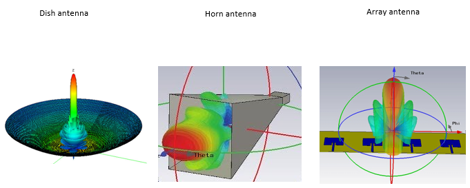
Dish antenna, on the left : one narrow main lobe rises straight out of the reflector, with small side lobes near its base. The reflector shape fixes the direction.Horn antenna, in the middle : a wider lobe comes out of the mouth of the horn. Its direction is also fixed by how the horn is mounted.Array antenna, on the right : four patch elements on a flat board form a main lobe with several side lobes. The Theta and Phi axes mark the angles that the array can steer electronically.
Let's see how the array changes direction without moving. Each element transmits the same signal with a different phase. For elements spaced d apart, a beam at angle θ from broadside needs a phase step of 2π d sinθ / λ between neighbouring elements. With the common half-wavelength spacing, the step becomes π sinθ. So a beam steered 30 deg away from broadside needs 90 deg of phase between elements. At 5.5 GHz the wavelength is about 5.5 cm, so half-wavelength spacing is about 2.7 cm, and a small array fits inside an AP. The gain also grows with the number of elements. N elements that add in phase give 10 log10(N) dB of array gain, so 4 antennas give about 6 dB and 8 antennas about 9 dB.
A WiFi AP rarely points one geometric beam, though. Indoors, the signal reaches the station over many reflected paths, and the channel is different on each subcarrier. So the AP computes a steering matrix for each subcarrier or group of subcarriers from the measured channel. The resulting pattern is whatever makes the paths add up at the station, and it may not look like a single lobe at all. For this, the AP must know the channel to the station. That is the question of the next section.
Phase, not motors : an array steers its beam by the phase step between elements, π sinθ for half-wavelength spacing.More antennas, more gain : 4 elements in phase give about 6 dB, 8 elements about 9 dB.WiFi beams follow the channel : indoors the steering is computed per subcarrier from channel knowledge, not from a direction.
How to perform BeamForming in WiFi protcol ?
Now we know what is the beamforming and why we want to use the technique. Then a question arises. How the transmitter (BeamFormer) wants to know which direction it should point the beam to ? If the location of the transmitter and reciever is fixed, the determining the beam direction would be simple. You just point the antenna of transmitter and reciever in such a way that they are aligned in line of sight at the time of installation (Most of satellite communication or microwave link determine the beam direction in this way). However, in case of WiFi the position of AP and Station, especially the position of Stations changes very frequently. So a working beam direction now would not work in a few minutes later. It mean that there should be some mechanism by which the BeamFormer figure out the proper direction of the beam dynamically. This kind of Dynamic mechanism is implemented as a protocol in 802.11. There are two types of beamforming process, called Implicit and Explicit process.
Implicit Process : Beamformer figure out the proper beam implcitely from a specific reference signal from beamformee. In this case, the beamformee does not explicitly tell to BeamFormer anything about what is the best beam for itself.Explicit Process : Beamformer figures out the best beam from the explicit information sent by beamformee. In this case, the beamformee figures out what is the best beam for it based on the reference signal from beamformer and the result of the best beam selection explicitely to the beamformer.
These two process can be summarized in illustration as follows.
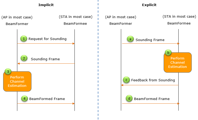
Implicit, steps 1 to 4 : the BeamFormer, the AP in most case, sends a Request for Sounding. The BeamFormee answers with a Sounding Frame. The BeamFormer performs channel estimation on that frame and then sends the BeamFormed Frame. So the BeamFormer measures the reverse link, from the station to the AP.Explicit, steps a to d : the BeamFormer sends a Sounding Frame, and the BeamFormee performs channel estimation on it. The BeamFormee returns the Feedback from Sounding, and the BeamFormer then sends the BeamFormed Frame. So the forward link itself is measured.
The implicit process depends on channel reciprocity. WiFi is TDD, so the air channel from the AP to the station is the same as the channel back on the same frequency. But the transmit and receive RF chains inside each device are not identical. So the AP must calibrate its chains before a reverse-link estimate can steer the forward link. Its advantage is that the station needs no beamforming support. The explicit process avoids the calibration, because the BeamFormee measures the forward channel directly. The cost is the feedback frame, which takes airtime.
802.11n defined both processes. 802.11ac kept only the explicit one, with NDP sounding, and 802.11ax and 802.11be use the same sequence. The BeamFormer first sends an NDP Announcement, which names the stations that should measure. It then sends an NDP, a null data packet that carries the preamble with its training fields but no data. Each BeamFormee estimates the channel from the NDP and returns a Compressed Beamforming Report. The report does not carry the raw channel. It carries the steering matrix V for each subcarrier group, compressed into Givens rotation angles called phi and psi. For MU-MIMO, the AP needs a report from every station in the group. 802.11ac asks the further stations with a Beamforming Report Poll frame, and 802.11ax uses a Trigger frame of the Beamforming Report Poll type.
Implicit needs calibration, explicit needs airtime : the two processes trade RF chain calibration against feedback overhead.NDPA, NDP, report : this three-frame exchange is the sounding sequence of 802.11ac and later.The feedback is a matrix, not a direction : the station reports the V matrix as phi and psi angles per subcarrier group.
References
- packet-ieee80211.c : Wireshark IEEE 802.11 dissector, used for the frame and field names NDP Announcement, Compressed Beamforming Report, phi and psi angles, and the Beamforming Report Poll trigger type.
YouTube
- NETGEAR implicit beamforming (Feb 2016)
- Beamforming both explicit and implicit (Aug 2020)
- 802 11n 802 11ac MIMO Transmit Beamforming (Dec 2020)