DCF is one of the most fundamental functionality of WLAN MAC Protocol. The main role of this function is to schedule the data transmission based on CSMA/CA, Backoff and various IFS(Inter Frame Space). Overall DCF cycle (algorithm) goes as follows (of course, it would look much complicated than just CSMA/CA + Backoff :). Just take a look at the overall picture and try to make your own story out of this.
DCF has no central scheduler. Every station follows the same rules for waiting and backing off, and those rules alone decide who transmits next. Let's first walk through one cycle with the picture below. Then we put numbers on the interframe spaces and the backoff, and finally we see how much of the PHY rate survives one cycle.
- How does one DCF cycle run ?
- How long are SIFS, slot time and DIFS ?
- How does the random backoff work ?
- How much of the PHY rate does one DCF cycle deliver ?
How does one DCF cycle run ?
One DCF cycle moves one data frame from a source to a destination, and every other station has to stay quiet while it happens. The cycle below uses the RTS/CTS exchange, which is optional. Without it, the source sends Data straight after DIFS and the backoff.
The diagram below has three rows: Src, Dest and Other, for all the remaining stations. The green circles number the events in the order of the steps listed under the picture. The upper part shows the frames on the air. The lower part shows how the other stations defer, first on their NAV and then with a random backoff in the Contention Window.
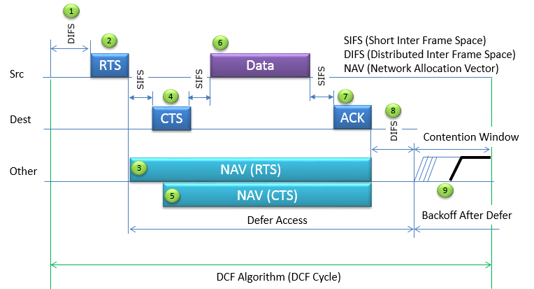
Two details in the picture are worth a closer look. First, the NAV from the RTS starts at step 3, and the NAV from the CTS starts later, at step 5. Both end at the same point, the end of the ACK. The CTS NAV matters for a hidden station, one that can hear Dest but not Src. Such a station never sees the RTS, so the CTS is its only warning. Second, the legend expands DIFS as Distributed Inter Frame Space, while step 1 calls it DCF Inter Frame Space. Both refer to the same gap, the one that DCF uses before a new transmission.
Only the first access is contended : after DIFS and the backoff, CTS, Data and ACK each follow after SIFS.NAV is virtual carrier sensing : the other stations defer because of the Duration value, even when they cannot hear the medium. See the NAV page.RTS/CTS protects against hidden stations : the CTS reaches stations around Dest that cannot hear Src.
How long are SIFS, slot time and DIFS ?
The picture shows the gaps but not their lengths. The lengths come from the PHY, and they are what gives the ACK and the CTS priority over a new transmission.
SIFS is the time a station needs to turn around from receiving to transmitting. The slot time is the unit of the backoff, and it is long enough for a station to detect that another station started in the previous slot. DIFS is built from these two: DIFS = SIFS + 2 x slot time. PIFS, which the point coordinator uses in PCF, sits in between: PIFS = SIFS + slot time. The table below gives the values used by the ns-3 simulator for each PHY, with DIFS computed from the formula.
PHY |
SIFS, microseconds |
Slot, microseconds |
DIFS, microseconds |
CWmin, slots |
DSSS, 802.11b |
10 |
20 |
50 |
31 |
ERP, 802.11g with short slot |
10 |
9 |
28 |
15 |
OFDM 20 MHz, 802.11a and later in 5 GHz |
16 |
9 |
34 |
15 |
The priority follows from the order SIFS < PIFS < DIFS. A destination answers with an ACK after SIFS. Any station that wants to start a new frame must first see the medium idle for DIFS, which is two slot times longer. So the ACK always starts before any new contention can end, and it never collides with a new frame. The same holds for CTS and for Data after CTS. In a mixed 802.11b/g network, the ERP stations fall back to the 20 microsecond slot of DSSS, so DIFS returns to 50 microseconds. 802.11g in 2.4 GHz also adds a 6 microsecond signal extension after each OFDM frame.
DIFS = SIFS + 2 x slot : 50, 28 or 34 microseconds, depending on the PHY.The shorter gap wins : responses after SIFS always start before a new contention after DIFS.OFDM made the gaps shorter : the 9 microsecond slot cuts the cost of every backoff slot to less than half.
How does the random backoff work ?
DIFS alone cannot separate two stations that both wait for the medium. They would both see the same idle DIFS and start at the same moment. Step 9 in the picture solves this with a random wait, and the size of that wait adapts to how crowded the channel is.
Each station draws a backoff counter as a random integer from 0 to CW, the contention window. After the medium has been idle for DIFS, the station counts the counter down by one for every idle slot. If another station starts to transmit, the counter freezes. It resumes after the medium has again been idle for DIFS. The station transmits when its counter reaches zero. So a station that lost one round keeps its remaining count and gets closer to the front each time.
CW starts at CWmin. After each failed transmission, the station roughly doubles it, CW = min(CWmax, 2k x (CWmin + 1) - 1) after k failures. With CWmin = 15 and CWmax = 1023, the sequence is 15, 31, 63, 127, 255, 511 and 1023. After a success, CW returns to CWmin. This is binary exponential backoff. It spreads the stations over more slots exactly when collisions show that the channel is crowded.
A few numbers make this concrete. With CW = 15, the mean backoff is 7.5 slots, or 67.5 microseconds with a 9 microsecond slot. Two stations that draw independently pick the same slot with a probability of 1/16, or 6.25 percent. After two failures CW is 63, and that probability drops to 1/64, about 1.6 percent.
The counter freezes, it does not restart : a station that waited long keeps its advantage in the next round.Collisions make the window grow : CW goes from 15 up to 1023 and returns to 15 after a success.The mean backoff is CW / 2 slots : 67.5 microseconds for CW = 15 and a 9 microsecond slot.
How much of the PHY rate does one DCF cycle deliver ?
Every gap and every control frame in the cycle takes air time without carrying user data. So a station that transmits at 54 Mbps never delivers 54 Mbps, even when it is alone on the channel. Let's add up one cycle to see how large the gap is.
The example uses a 5 GHz OFDM PHY. Data goes at 54 Mbps, and RTS, CTS and ACK go at 24 Mbps. The data frame carries 1500 bytes of payload with a 24-byte MAC header and a 4-byte FCS. An OFDM frame lasts 20 microseconds of preamble and SIGNAL, plus 4 microseconds for each symbol. The number of symbols is (16 + 8 x bytes + 6) / bits per symbol, rounded up. That gives 216 bits per symbol at 54 Mbps and 96 at 24 Mbps. An RTS has 20 bytes, and a CTS or ACK has 14.
Part of the cycle |
Duration, microseconds |
How it is computed |
DIFS |
34 |
Idle medium before contention |
Mean backoff |
67.5 |
7.5 slots x 9 microseconds |
RTS |
28 |
20 bytes at 24 Mbps |
SIFS |
16 |
|
CTS |
28 |
14 bytes at 24 Mbps |
SIFS |
16 |
|
Data |
248 |
1528 bytes at 54 Mbps, 57 symbols |
SIFS |
16 |
|
ACK |
28 |
14 bytes at 24 Mbps |
Total |
481.5 |
1500 bytes of payload delivered |
The cycle delivers 1500 x 8 = 12000 bits in 481.5 microseconds, which is 24.9 Mbps. Without RTS/CTS, the cycle drops RTS, CTS and two SIFS and lasts 393.5 microseconds, which gives 30.5 Mbps. So even a single station with no collisions gets 46 to 56 percent of the PHY rate. This is why the aggregation of 802.11n and later matters so much, because it spreads one contention and one acknowledgement over many frames.
The same numbers also explain steps 3 and 5. The Duration field in the RTS covers everything that follows it: 3 x SIFS + CTS + Data + ACK = 352 microseconds. The CTS carries 352 - 16 - 28 = 308 microseconds, because one SIFS and the CTS itself have already passed. The Data frame carries SIFS + ACK = 44 microseconds. Each NAV therefore ends at the end of the ACK, as the two NAV bars in the picture show.
54 Mbps on the PHY is about 25 to 30 Mbps of payload : gaps, backoff, preamble and control frames take the rest.RTS/CTS has a price : in this example, it costs 88 microseconds per frame, about 18 percent of the cycle.The Duration values chain together : RTS 352, CTS 308 and Data 44 microseconds all point to the end of the ACK.