|
Resource Grid - Downlink : CORESET, PDSCH, PDSCH DMRS
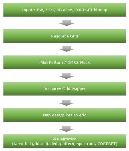
In this note, I will implement a python script to construct and visualize NR Downlink Resource Grid which includes very basic components : CORESET, PDSCH, PDSCH DMRS. I might have included more components like SSB, CSI-RS, PTRS etc but I wanted to make it simple at first.
This script leverages NVIDIA's Sionna library for OFDM resource grid creation and mapping, providing a comprehensive visualization framework using Tkinter-based tabbed GUI.
Followings are brief descriptions on each procedure with the focus on sionna api
-
Inputs: Channel BW, subcarrier spacing, RB allocation (START_RB, NUM_RBS), CORESET bitmap/duration/start symbol, DMRS config.
-
ResourceGrid (sionna.phy.ofdm.ResourceGrid): Constructs the OFDM grid (FFT size, guards, symbols, pilots placeholder).
-
PilotPattern / DMRS masks: Builds DMRS positions per Type A rules; CORESET masks derived from bitmap.
-
ResourceGridMapper (sionna.phy.ofdm.ResourceGridMapper): Maps data/pilot symbols into the grid using masks.
-
Visualization: Multiple Tkinter tabs render full grid, zoomed view, resource pattern (PDSCH/DMRS/CORESET), spectrum (PSD/spectrogram), and CORESET detail.
Toolkits for the script
I didn't write the code myself. What I did was just prompting for AI tool and did basic check up for the output. Followings are the tool kits that I used for this script
- Scripting IDE : Cursor
- Version: 2.1.50 (system setup)
- VSCode Version: 1.105.1
- Commit: 56f0a83df8e9eb48585fcc4858a9440db4cc7770
- Date: 2025-12-06T23:39:52.834Z
- Electron: 37.7.0
- Chromium: 138.0.7204.251
- Node.js: 22.20.0
- V8: 13.8.258.32-electron.0
- OS: Windows_NT x64 10.0.26100
- AI Model : Opus 4.5 (as of Dec 7, 2025)
- Python Info : Check out this note for the detailed installation proces that I went through
|
==== Python Version ====
3.12.3 (main, Nov 6 2025, 13:44:16) [GCC 13.3.0]
==== Python Executable ====
/home/jaeku/nvidia/venv-sionna/bin/python3
==== Platform Info ====
Linux-6.6.87.2-microsoft-standard-WSL2-x86_64-with-glibc2.39
('main', 'Nov 6 2025 13:44:16')
==== Site-Packages Directories ====
['/home/jaeku/nvidia/venv-sionna/lib/python3.12/site-packages', '/home/jaeku/nvidia/venv-sionna/local/lib/python3.12/dist-packages', '/home/jaeku/nvidia/venv-sionna/lib/python3/dist-packages', '/home/jaeku/nvidia/venv-sionna/lib/python3.12/dist-packages']
==== sys.path ====
/home/jaeku/nvidia
/usr/lib/python312.zip
/usr/lib/python3.12
/usr/lib/python3.12/lib-dynload
/home/jaeku/nvidia/venv-sionna/lib/python3.12/site-packages
==== Installed Packages ====
absl-py == 2.3.1
asttokens == 3.0.1
astunparse == 1.6.3
certifi == 2025.11.12
charset-normalizer == 3.4.4
comm == 0.2.3
contourpy == 1.3.3
cycler == 0.12.1
decorator == 5.2.1
drjit == 1.2.0
executing == 2.2.1
flatbuffers == 25.9.23
fonttools == 4.61.0
gast == 0.7.0
google-pasta == 0.2.0
grpcio == 1.76.0
h5py == 3.15.1
idna == 3.11
importlib_resources == 6.5.2
ipydatawidgets == 4.3.5
ipython == 9.8.0
ipython_pygments_lexers == 1.1.1
ipywidgets == 8.1.8
jedi == 0.19.2
jupyterlab_widgets == 3.0.16
keras == 3.12.0
kiwisolver == 1.4.9
libclang == 18.1.1
Markdown == 3.10
markdown-it-py == 4.0.0
MarkupSafe == 3.0.3
matplotlib == 3.10.7
matplotlib-inline == 0.2.1
mdurl == 0.1.2
mitsuba == 3.7.1
ml_dtypes == 0.5.4
namex == 0.1.0
numpy == 1.26.4
opt_einsum == 3.4.0
optree == 0.18.0
packaging == 25.0
parso == 0.8.5
pexpect == 4.9.0
pillow == 12.0.0
pip == 25.3
prompt_toolkit == 3.0.52
protobuf == 6.33.2
ptyprocess == 0.7.0
pure_eval == 0.2.3
Pygments == 2.19.2
pyparsing == 3.2.5
python-dateutil == 2.9.0.post0
pythreejs == 2.4.2
requests == 2.32.5
rich == 14.2.0
scipy == 1.16.3
setuptools == 80.9.0
sionna == 1.2.1
sionna-rt == 1.2.1
six == 1.17.0
stack-data == 0.6.3
tensorboard == 2.20.0
tensorboard-data-server == 0.7.2
tensorflow == 2.20.0
termcolor == 3.2.0
traitlets == 5.14.3
traittypes == 0.2.3
typing_extensions == 4.15.0
urllib3 == 2.6.0
wcwidth == 0.2.14
Werkzeug == 3.1.4
wheel == 0.45.1
widgetsnbextension == 4.0.15
wrapt == 2.0.1
|
Source Code and Output
You can get the source code for this note here. I would not describe / explain on every single line of the code since AI (e.g, chatGPT, Gemini etc) will explain better than I do.
Disclaimer !!!
I have checked and fixed some obvious issues of the script while I am prompting the script, but I haven't verified all the details of the implementation. So there likely to be bugs / errors that I missed. So take this purely as an educational purpose for getting some high level idea on how 3GPP NR Phy specification can be implemented
The script output some part of the result in text and some part in graphics.
Followings are the output of the code in text
|
2025-12-07 21:28:01.913649: I external/local_xla/xla/tsl/cuda/cudart_stub.cc:31] Could not find cuda drivers on your machine, GPU will not be used.
2025-12-07 21:28:01.929677: I tensorflow/core/util/port.cc:153] oneDNN custom operations are on. You may see slightly different numerical results due to floating-point round-off errors from different computation orders. To turn them off, set the environment variable `TF_ENABLE_ONEDNN_OPTS=0`.
2025-12-07 21:28:02.489031: I tensorflow/core/platform/cpu_feature_guard.cc:210] This TensorFlow binary is optimized to use available CPU instructions in performance-critical operations.
To enable the following instructions: AVX2 AVX_VNNI FMA, in other operations, rebuild TensorFlow with the appropriate compiler flags.
2025-12-07 21:28:02.757062: I tensorflow/core/util/port.cc:153] oneDNN custom operations are on. You may see slightly different numerical results due to floating-point round-off errors from different computation orders. To turn them off, set the environment variable `TF_ENABLE_ONEDNN_OPTS=0`.
2025-12-07 21:28:02.760282: I external/local_xla/xla/tsl/cuda/cudart_stub.cc:31] Could not find cuda drivers on your machine, GPU will not be used.
============================================================
NR Resource Grid Configuration
============================================================
Channel Bandwidth: 20 MHz
Subcarrier Spacing: 30 kHz
Max RBs (for BW/SCS): 51
START_RB: 10
NUM_RBS: 24
RB Range: RB 10 to RB 33
Allocation: 24/51 RBs (47.1%)
Allocated Subcarriers: 288
OFDM Symbols per Slot: 14
FFT Size: 2048
Guard Carriers: 838 (left), 922 (right)
------------------------------------------------------------
DMRS Configuration (3GPP TS 38.211)
------------------------------------------------------------
DMRS Config Type: Type 1 (comb-2)
DMRS Length: 1 symbol(s)
DMRS First Symbol (l0): 2
DMRS Additional Pos: 3
DMRS Symbol Positions: [2, 5, 8, 11]
DMRS CDM Group: 0
DMRS Ports: [0]
DMRS Delta Shift: 0
CDM Groups w/o Data: 1
------------------------------------------------------------
CORESET Configuration (3GPP TS 38.331)
------------------------------------------------------------
CORESET Enabled: Yes
CORESET ID: 1
Freq Domain Bitmap: 111100000000000... (45 bits)
CORESET RBs: 24 RBs (RB 0 to 23, contiguous)
CORESET Duration: 2 symbol(s)
CORESET Start Symbol: 0
CCE-REG Mapping: interleaved
REG Bundle Size: 6
Interleaver Size: 2
Shift Index: 0
CORESET REGs: 48
CORESET CCEs: 8
Overlap with PDSCH: 14 RBs
CORESET Data REs: 252
CORESET DMRS REs: 84
============================================================
Creating NR DMRS Type A pilot pattern (3GPP TS 38.211)...
2025-12-07 21:28:04.640002: E external/local_xla/xla/stream_executor/cuda/cuda_platform.cc:51] failed call to cuInit: INTERNAL: CUDA error: Failed call to cuInit: UNKNOWN ERROR (303)
DMRS mask shape: (1, 1, 14, 288)
DMRS pilots shape: (1, 1, 576)
Number of DMRS REs: 576
DMRS Info:
- CDM Groups Used: [0]
- Delta Shift: 0
- Ports: [0]
- DMRS Subcarriers/Symbol: 144
Incorporating CORESET into pilot pattern...
DMRS REs: 576
CORESET REs: 336
Combined reserved REs: 912
Creating Resource Grid...
Resource Grid created:
FFT Size: 2048
Num OFDM Symbols: 14
Num Subcarriers: 288
Num Data Symbols: 3120
Pilot Pattern: Custom NR DMRS Type A
Creating Resource Grid Mapper...
Number of data symbols to map: 3120
Data symbols shape: (1, 1, 1, 3120)
Resource grid shape: (1, 1, 1, 14, 2048)
============================================================
PDSCH RE Mapping Verification (3GPP TS 38.214)
============================================================
Reserved REs (PDSCH should NOT be mapped here):
Total REs in allocation: 4032
DMRS REs: 576
CORESET REs: 336
PTRS REs: 0
Total Reserved REs: 912
Available for PDSCH Data: 3120
Overhead: 22.62%
PDSCH Mapping Order Verification:
Number of Data REs mapped: 3120
Mapping order correct: YES ✓
CORESET data violations: 0 ✓
First data RE: Symbol 0, SC 168
Last data RE: Symbol 13, SC 287
3GPP Compliance Check (TS 38.214 Section 5.1.4):
[✓] Frequency-first mapping (lowest to highest SC, then next symbol)
[✓] DMRS REs excluded (via pilot pattern)
[✓] CORESET REs excluded (REs not available for PDSCH)
[✓] PTRS REs excluded (PTRS disabled)
[N/A] CSI-RS REs (not configured)
[INFO] VRB-to-PRB mapping: Non-interleaved (direct mapping)
============================================================
============================================================
Launching Resource Grid Viewer...
============================================================
[DEBUG] Spectrum Tab Data:
rg_freq shape: (14, 2048)
rg_freq non-zero count: 3696
Time domain signal length: 28672
Sampling rate: 61.44 MHz
Signal duration: 466.67 µs
Time signal power: 267.7714
Welch PSD shape: (1024,)
Frequency range: -30.72 to 30.66 MHz
PSD range: -89.6 to -44.0 dB/Hz
START_RB: 10, NUM_RBS: 24
Allocated center offset: -1.26 MHz
Allocated band: -5.58 to 3.06 MHz
Per-symbol PSD shape: (14, 256)
Per-symbol freq range: -30.72 to 30.48 MHz
|
Followings are the snapshots of graphical output (NOTE : If you want to get images for better resolution, I would suggest you to install the sionna on your PC and run the script that I shared).
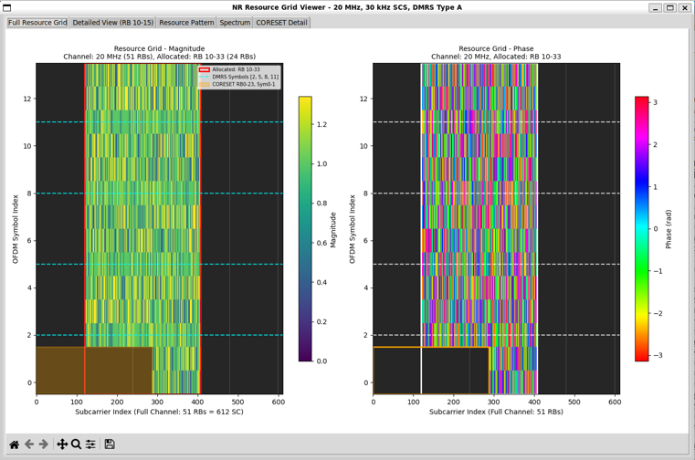
Full Resource Grid
The screenshot shows the final constructed NR resource grid after applying all configuration steps in the script. The carrier configuration is 20 MHz bandwidth with 30 kHz subcarrier spacing, resulting in 51 RBs = 612 subcarriers across the full channel.
Followings are brief description of each components in this view :
- Only a subset of RBs is allocated for transmission.
- Active RBs appear as a colored vertical block in the middle of the grid.
- Unallocated RBs on both sides remain empty (dark), confirming correct RB masking.
- The left panel displays magnitude of the resource grid.
- Data symbols occupy most REs in the allocated RB range.
- DMRS symbols are visible with distinct magnitude patterns.
- Reserved regions (e.g., CORESET) are clearly excluded from data mapping.
- The right panel displays phase of the same grid.
- Data symbols show random-looking phase distribution, consistent with QAM modulation.
- DMRS symbols show structured phase behavior, reflecting deterministic reference sequences.
- DMRS Type A placement is correctly applied.
- DMRS symbols appear only at expected OFDM symbol indices.
- No collision between data and DMRS is observed.
- The CORESET region is clearly carved out.
- Control resources are confined to the configured frequency and symbol range.
- Data symbols do not leak into CORESET-reserved REs.
- Dashed horizontal lines mark OFDM symbol indices of interest, helping verify
- symbol-domain configurations such as DMRS positions and CORESET duration.
- The visualization confirms the correct order of operations in the script:
- configuration → grid creation → DMRS masking → resource mapping → symbol placement.
- This full-grid view acts as a sanity and debugging check.
- Any mistake in RB allocation, DMRS configuration, or CORESET bitmap would be immediately visible as misplaced energy or symbol collisions.
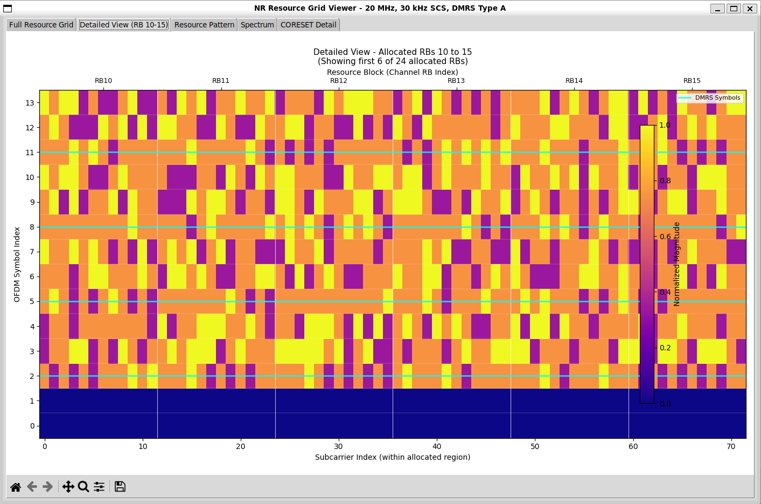
Defailed View
This view provides a maginified view of only a small portions of the full resource allocation area to provide more detailed aspect of the resource grid.
Followings are brief description of each components in this view :
-
This view zooms into a small RB subset (RB10 to RB15) taken from the full allocated bandwidth.
-
Only 6 RBs are shown here, even though more RBs are allocated overall.
-
This makes individual RE-level behavior clearly visible.
-
The x-axis represents subcarrier indices within the allocated region.
-
Each RB spans 12 subcarriers, and vertical separators mark RB boundaries.
-
RB labels at the top (RB10–RB15) confirm correct frequency-domain indexing.
-
The y-axis represents OFDM symbol indices within a slot.
-
DMRS Type A symbols are explicitly highlighted.
-
They appear at specific OFDM symbols only.
-
The DMRS locations match the configured Type-A mapping rules.
-
No data symbols are placed on DMRS REs, confirming correct masking.
-
Data symbols fill all remaining non-reserved REs.
-
The bottom OFDM symbols are empty or reserved.
-
This typically corresponds to control, guard, or intentionally unused regions.
-
It confirms that data mapping starts only after reserved symbols are excluded.
-
The color bar on the right shows normalized magnitude.
-
This detailed view is primarily a validation tool.
-
It confirms RE-level correctness of RB allocation.
-
It verifies DMRS symbol timing and frequency placement.
-
It ensures there is no collision between data, pilots, and reserved regions.
-
Compared to the full-grid view, this plot answers “what exactly is happening inside one RB group”,
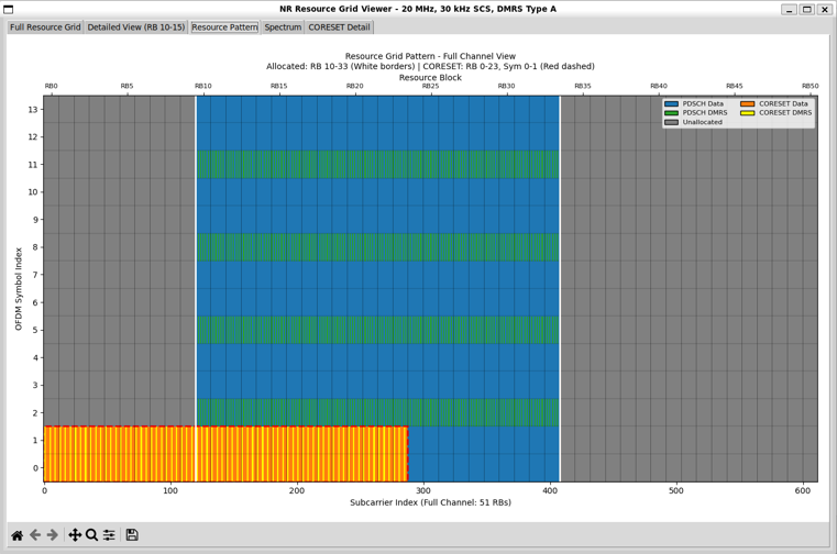
Resource Pattern
This view shows the logical resource pattern of the entire channel, rather than symbol magnitude or phase. The carrier is 20 MHz, 30 kHz SCS, covering 51 RBs across the full frequency span.
Followings are brief description of each components in this view :
-
Frequency-domain allocation is clearly separated:
-
Different resource types are color-coded for clarity:
-
PDSCH Data occupies most REs in the allocated RB region.
-
PDSCH DMRS appears as horizontal bands at specific OFDM symbol indices.
-
CORESET Data and DMRS are shown in the lower OFDM symbols.
-
Unallocated regions remain uniformly grey.
-
DMRS Type A structure is easy to verify:
-
DMRS symbols repeat periodically across frequency within the allocated RBs.
-
DMRS appears only on the configured OFDM symbols.
-
No DMRS appears outside the allocated PDSCH region.
-
The CORESET region is explicitly carved out:
-
CORESET occupies RB0–RB23 and OFDM symbols 0–1, marked with red dashed borders.
-
Control resources are isolated from PDSCH resources both in time and frequency.
-
The time-domain separation is visually clear:
-
Lower OFDM symbols are dominated by CORESET.
-
Higher OFDM symbols are used for PDSCH data and DMRS.
-
No overlap exists between control and data regions.
-
This pattern view confirms correct masking and prioritization rules:
-
CORESET takes precedence over PDSCH.
-
DMRS masks are applied before data mapping.
-
Unallocated RBs never carry data or pilots.
-
Compared to the full-grid magnitude/phase views, this plot focuses on “what type of signal is placed where”, rather than “what complex values those signals carry.”
-
This visualization is especially useful for:
-
Verifying RB allocation logic
-
Checking CORESET frequency and symbol spans
-
Confirming DMRS placement rules
-
Explaining NR resource mapping concepts in a tutorial context
Spectrum
This view connects the time–frequency resource grid to the actual RF spectrum seen after OFDM modulation. The carrier configuration is 20 MHz bandwidth with 30 kHz SCS, and only RB10–RB33 (24 RBs) are allocated.
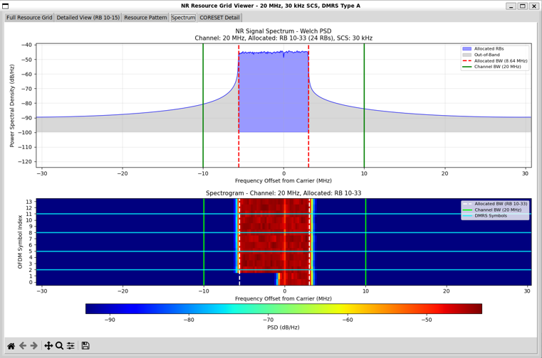
Followings are brief description of each components in this view :
-
The top plot shows the power spectral density (PSD) computed using Welch’s method.
-
The blue region corresponds to the occupied bandwidth of the allocated RBs.
-
The red dashed vertical lines mark the edges of the allocated RB region.
-
The green vertical lines indicate the full channel bandwidth limits.
-
Energy is confined strictly within the allocated RB bandwidth.
-
The grey area represents out-of-band spectrum.
-
The bottom plot is a spectrogram, showing spectrum versus OFDM symbol index.
-
DMRS symbol locations are visible in the spectrogram.
-
The spectrum view verifies several critical aspects simultaneously:
-
RB allocation is correctly reflected in the frequency domain.
-
DMRS placement in time aligns with symbol-domain configuration.
-
No transmission occurs outside the configured channel bandwidth.
-
This plot is especially useful as a final validation step.
-
Conceptually, this view answers the question: “Does the resource grid we built produce the spectrum we expect?”
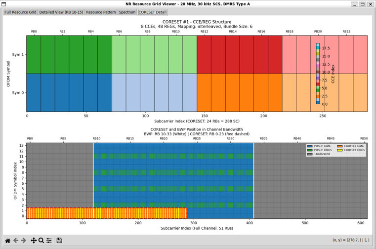
CORESET Details
This view focuses specifically on the CORESET configuration and its internal structure, separated from the PDSCH grid.
Followings are brief description of each components in this view :
-
The top panel shows the CCE–REG mapping structure of the CORESET.
-
Interleaved mapping is used.
-
REG bundle size is 6, which determines how REGs are grouped before interleaving.
-
The color-coded blocks in the top panel represent CCE indices.
-
The x-axis of the top panel shows subcarrier indices within the CORESET bandwidth.
-
The y-axis of the top panel represents OFDM symbols used by the CORESET.
-
The bottom panel places the CORESET back into the full resource grid context.
-
The CORESET is confined to the lower OFDM symbols.
-
Its frequency span is limited to RB0–RB23, marked with dashed red borders.
-
PDSCH and CORESET regions are clearly separated.
-
CORESET DMRS and data REs are both visible.
-
This view is especially useful for validating:
-
CORESET frequency and symbol duration
-
CCE count and REG bundling
-
Interleaving behavior
-
Control–data isolation at the RE level
-
Conceptually, this plot answers the question:“How exactly is PDCCH control information packed into the resource grid?”
Source Code Overview
Even though I no longer need to describe every single line of code in the age of AI, I still think it is valuable to write down some key points. This is not to show off the code itself. It is to record the intention behind the script. I want to clarify what I was trying to do, what kind of idea I had in mind, and what kind of problems this script is designed to solve. This allows the reader to connect the final result with the original design goal. It also helps me later when I come back to
this code after a long time and forget my own thinking process.
You may not need all of these details if your only goal is to understand the output of the script. For simple usage, you can often treat the script as a black box. You run it. You look at the result. You move on. In many cases this is enough. However, if you want to modify, revise, or extend the script for your own purpose, the situation changes. You would need to know which part of the code is doing what. You would need to know which parameters control which behavior. You would also need to
know what kind of assumptions I made when I first wrote the code. In that case, a clear description of the code is not a luxury. It becomes a kind of map.
One of the best ways to learn anything related to programming is still very old-fashioned. You break it and then you fix it. You change a small part of the script and see what goes wrong. You check the error. You adjust. You run it again. This loop may look inefficient at first, but it forces your brain to connect cause and effect inside the code. So my intention with these explanations is not just to document the script. It is to give you enough context so that you can safely break it, understand
why it broke, and then fix it in a way that matches your own idea. This process is painful sometimes, but it is also the part that makes the knowledge stick to your brain.
Key Features
- NR Resource Grid Generation: Creates a 5G NR downlink resource grid with configurable bandwidth, subcarrier spacing, and RB allocation
- 3GPP-Compliant DMRS: Implements DMRS Type A with support for multiple positions, CDM groups, delta shift, and OCC
- CORESET Support: Configurable CORESET regions using 3GPP-compliant 45-bit frequency domain bitmap
- PDSCH RE Mapping Verification: Validates that PDSCH data follows 3GPP TS 38.214 mapping rules
- Multi-Tab Visualization: Interactive GUI with 5 tabs showing resource grid, detailed view, pattern, spectrum, and CORESET details
What is Implemented ?
Followings are the features that I fully implemented (hopefully :)
|
Feature
|
Description
|
Reference
|
|
Resource Grid Creation
|
OFDM resource grid with configurable FFT size, guard carriers, and subcarrier spacing
|
TS 38.211
|
|
DMRS Type A Time Domain
|
Symbol positions based on l0 and additional position (0-3)
|
TS 38.211 Table 7.4.1.1.2-3
|
|
DMRS Type 1 Frequency Pattern
|
Comb-2 pattern with even/odd subcarrier allocation
|
TS 38.211 Section 7.4.1.1.2
|
|
DMRS CDM Groups
|
Support for CDM groups 0 and 1 (Type 1)
|
TS 38.211 Table 7.4.1.1.2-1
|
|
DMRS Delta Shift
|
Frequency offset for inter-cell interference management
|
TS 38.211
|
|
DMRS OCC
|
Orthogonal Cover Codes for ports 0-3 (single-symbol) and 0-7 (double-symbol)
|
TS 38.211
|
|
Multiple DMRS Ports
|
Ports 0-3 for Type 1 configuration
|
TS 38.211
|
|
CORESET Configuration
|
Full CORESET setup with bitmap, duration, start symbol
|
TS 38.331
|
|
CORESET Bitmap
|
45-bit frequency domain bitmap (each bit = 6 RBs)
|
TS 38.331
|
|
CORESET CCE/REG Mapping
|
Interleaved and non-interleaved mapping support
|
TS 38.213
|
|
PDCCH DMRS Pattern
|
Subcarriers 1, 5, 9 within each RB in CORESET
|
TS 38.211 Section 7.3.2.2
|
|
RB Allocation Validation
|
START_RB and NUM_RBS boundary checking
|
-
|
|
Channel Bandwidth Tables
|
MAX_RBS and FFT sizes for 5–100 MHz (FR1)
|
TS 38.101
|
|
PDSCH RE Mapping Verification
|
Validates frequency-first mapping and reserved RE exclusion
|
TS 38.214 Section 5.1.4
|
|
Spectrum Analysis
|
Welch PSD and spectrogram visualization
|
-
|
|
Interactive GUI
|
5-tab Tkinter interface with matplotlib integration
|
-
|
What is Partially Implemented ?
|
Feature
|
Status
|
Notes
|
|
PTRS (Phase Tracking Reference Signal)
|
Basic mask generation
|
Time/frequency density supported; actual PTRS sequence not generated
|
|
DMRS Type 2
|
Basic structure only
|
Subcarrier positions defined; not fully validated
|
|
VRB-to-PRB Interleaved Mapping
|
Not functional
|
Only non-interleaved (direct) mapping is used
|
What is NOT Implemented ?
|
Feature
|
Description
|
Reference
|
|
CSI-RS
|
Channel State Information Reference Signal
|
TS 38.211 Section 7.4.1.5
|
|
PTRS Sequence Generation
|
Gold sequence for PTRS values
|
TS 38.211 Section 7.4.1.2.2
|
|
DMRS Gold Sequence
|
Uses random QPSK instead of proper Gold sequence
|
TS 38.211 Section 7.4.1.1.1
|
|
TRS (Tracking Reference Signal)
|
Not implemented
|
TS 38.211
|
|
SRS (Sounding Reference Signal)
|
Uplink signal, not applicable
|
TS 38.211
|
|
SSB (Synchronization Signal Block)
|
Not implemented
|
TS 38.211
|
|
PDSCH Rate Matching
|
Rate matching around reserved resources
|
TS 38.214
|
|
LDPC/Polar Encoding
|
Channel coding
|
TS 38.212
|
|
VRB-to-PRB Interleaved Mapping
|
Interleaved resource block mapping
|
TS 38.214 Section 5.1.4
|
|
Multi-Slot DMRS
|
DMRS spanning multiple slots
|
TS 38.211
|
|
Transform Precoding (DFT-s-OFDM)
|
Uplink feature
|
TS 38.211
|
|
Frequency Hopping
|
Intra/inter-slot frequency hopping
|
TS 38.214
|
|
BWP (Bandwidth Part) Switching
|
Dynamic BWP configuration
|
TS 38.214
|
Description of Parameters (Global Variables)
Debug Configuration
|
Parameter
|
Type
|
Default
|
Description
|
|
DEBUG
|
bool
|
True
|
Enable/disable debug print statements
|
Channel Bandwidth Configuration
|
Parameter
|
Type
|
Default
|
Description
|
|
CHANNEL_BW_MHZ
|
int
|
20
|
Channel bandwidth in MHz (5, 10, 15, 20, 25, 30, 35, 40, 45, 50, 60, 70, 80, 90, 100)
|
|
SUBCARRIER_SPACING
|
float
|
30e3
|
Subcarrier spacing in Hz (15e3, 30e3, 60e3, 120e3)
|
PRB Allocation Configuration
|
Parameter
|
Type
|
Default
|
Description
|
|
START_RB
|
int
|
10
|
Starting RB index (0 to MAX_RBS - NUM_RBS)
|
|
NUM_RBS
|
int
|
24
|
Number of RBs to allocate
|
|
NUM_OFDM_SYMBOLS
|
int
|
14
|
OFDM symbols per slot (fixed for normal CP)
|
Lookup Tables
|
Table
|
Description
|
|
MAX_RBS_TABLE
|
Maximum RBs per channel bandwidth and SCS (3GPP TS 38.101). Format: {BW_MHz: {SCS_kHz: max_RBs}}
|
|
FFT_SIZE_TABLE
|
FFT sizes for different bandwidths. Format: {BW_MHz: fft_size}
|
DMRS Time Domain Configuration
|
Parameter
|
Type
|
Default
|
Description
|
|
DMRS_SYMBOL_INDEX
|
int
|
2
|
First DMRS symbol position l0 (2 or 3 for Type A)
|
|
DMRS_ADD_POS
|
int
|
3
|
Additional position (0: 1 symbol, 1: 2 symbols, 2: 3 symbols, 3: 4 symbols)
|
|
DMRS_LENGTH
|
int
|
1
|
DMRS length (1: single-symbol, 2: double-symbol)
|
DMRS Frequency Domain Configuration
|
Parameter
|
Type
|
Default
|
Description
|
|
DMRS_CONFIG_TYPE
|
int
|
1
|
Configuration type (1: comb-2, 2: comb-3)
|
|
DMRS_CDM_GROUP
|
int
|
0
|
CDM group (0 or 1 for Type 1, 0-2 for Type 2)
|
|
DMRS_DELTA_SHIFT
|
int
|
0
|
Delta shift for frequency offset (0 or 1)
|
|
DMRS_NUM_CDM_GROUPS_WITHOUT_DATA
|
int
|
1
|
Number of CDM groups reserved (no data mapping)
|
|
DMRS_PORTS
|
list
|
[0]
|
List of DMRS ports (0-3 for Type 1)
|
DMRS OCC Configuration Tables
|
Table
|
Description
|
|
DMRS_TYPE1_CDM_GROUPS
|
Subcarrier positions per CDM group. CDM 0: even (0,2,4,6,8,10), CDM 1: odd (1,3,5,7,9,11)
|
|
DMRS_TYPE1_OCC
|
OCC patterns (w_f, w_t) for single-symbol DMRS ports 0-3
|
|
DMRS_TYPE1_OCC_DOUBLE
|
OCC patterns for double-symbol DMRS ports 0-7
|
PTRS Configuration
|
Parameter
|
Type
|
Default
|
Description
|
|
PTRS_ENABLED
|
bool
|
False
|
Enable/disable PTRS
|
|
PTRS_TIME_DENSITY
|
int
|
1
|
Time density: 1, 2, or 4 (every Nth symbol)
|
|
PTRS_FREQ_DENSITY
|
int
|
2
|
Frequency density: 2 or 4 (every Nth RB)
|
|
PTRS_RE_OFFSET
|
int
|
0
|
RE offset within RB
|
CSI-RS Configuration
|
Parameter
|
Type
|
Default
|
Description
|
|
CSI_RS_ENABLED
|
bool
|
False
|
Enable/disable CSI-RS (placeholder only)
|
CORESET Configuration
|
Parameter
|
Type
|
Default
|
Description
|
|
CORESET_ENABLED
|
bool
|
True
|
Enable/disable CORESET visualization
|
|
CORESET_ID
|
int
|
1
|
CORESET ID (0-11)
|
|
CORESET_FREQ_DOMAIN_BITMAP
|
str
|
'111100000...' (45 chars)
|
45-bit bitmap where each bit represents 6 RBs
|
|
CORESET_DURATION
|
int
|
2
|
Duration in OFDM symbols (1, 2, or 3)
|
|
CORESET_START_SYMBOL
|
int
|
0
|
Starting OFDM symbol (0-12)
|
|
CORESET_CCE_REG_MAPPING
|
str
|
'interleaved'
|
CCE-to-REG mapping ('interleaved' or 'nonInterleaved')
|
|
CORESET_REG_BUNDLE_SIZE
|
int
|
6
|
REG bundle size (Duration 1,2: {2,6}; Duration 3: {3,6})
|
|
CORESET_INTERLEAVER_SIZE
|
int
|
2
|
Interleaver size R (2, 3, or 6)
|
|
CORESET_SHIFT_INDEX
|
int
|
0
|
n_shift (0-274, typically cell ID mod 275)
|
|
CORESET_PRECODER_GRANULARITY
|
str
|
'sameAsREG-bundle'
|
Precoder granularity
|
|
CORESET_DMRS_SCRAMBLING_ID
|
int/None
|
None
|
DMRS scrambling ID (None = use cell ID)
|
Antenna Configuration
|
Parameter
|
Type
|
Default
|
Description
|
|
NUM_TX
|
int
|
1
|
Number of transmitters
|
|
NUM_STREAMS_PER_TX
|
int
|
1
|
Number of streams per transmitter
|
Derived Parameters (Calculated at Runtime)
|
Parameter
|
Description
|
|
MAX_RBS
|
Maximum RBs for configured BW/SCS (from MAX_RBS_TABLE)
|
|
FFT_SIZE
|
FFT size for configured BW (from FFT_SIZE_TABLE)
|
|
NUM_SUBCARRIERS
|
NUM_RBS * 12
|
|
MAX_SUBCARRIERS
|
MAX_RBS * 12
|
|
START_SUBCARRIER
|
START_RB * 12
|
|
END_SUBCARRIER
|
(START_RB + NUM_RBS) * 12
|
|
GUARD_LEFT
|
Left guard carriers based on FFT size and allocation
|
|
GUARD_RIGHT
|
Right guard carriers based on FFT size and allocation
|
|
DMRS_SYMBOLS
|
List of DMRS symbol indices (calculated from l0 and ADD_POS)
|
|
CORESET_NUM_RBS
|
Total RBs in CORESET (from bitmap)
|
|
CORESET_RB_LIST
|
List of RB indices in CORESET (from bitmap)
|
|
CORESET_NUM_REGS
|
CORESET_NUM_RBS * CORESET_DURATION
|
|
CORESET_NUM_CCES
|
CORESET_NUM_REGS / 6
|
Description of Functions
validate_rb_allocation(start_rb, num_rbs, max_rbs, channel_bw, scs_khz)
Validates RB allocation parameters and adjusts invalid values.
Parameters:
|
Parameter
|
Type
|
Description
|
|
start_rb
|
int
|
Starting RB index
|
|
num_rbs
|
int
|
Number of RBs to allocate
|
|
max_rbs
|
int
|
Maximum RBs for the channel BW/SCS
|
|
channel_bw
|
int
|
Channel bandwidth in MHz
|
|
scs_khz
|
int
|
Subcarrier spacing in kHz
|
Returns: tuple(valid_start_rb, valid_num_rbs, error_messages)
Validation Rules:
- num_rbs must be > 0
- num_rbs must not exceed max_rbs
- start_rb must be >= 0 and < max_rbs
- start_rb + num_rbs must not exceed max_rbs
validate_coreset_config(bitmap_info, duration, start_symbol, reg_bundle_size)
Validates CORESET configuration parameters according to 3GPP specifications.
Parameters:
|
Parameter
|
Type
|
Description
|
|
bitmap_info
|
dict
|
Parsed bitmap information from parse_coreset_bitmap()
|
|
duration
|
int
|
CORESET duration in OFDM symbols (1-3)
|
|
start_symbol
|
int
|
Starting OFDM symbol for CORESET
|
|
reg_bundle_size
|
int
|
REG bundle size
|
Returns: tuple(valid_duration, valid_start_sym, valid_reg_bundle, errors)
Validation Rules:
- Duration must be 1, 2, or 3
- Start symbol + duration must not exceed 14
- REG bundle size must be valid for the duration (Duration 1,2: {2,6}; Duration 3: {3,6})
parse_coreset_bitmap(bitmap_str, max_rbs)
Parses the 45-bit CORESET frequency domain bitmap according to 3GPP TS 38.331.
Parameters:
|
Parameter
|
Type
|
Description
|
|
bitmap_str
|
str
|
45-character string of '0' and '1'
|
|
max_rbs
|
int
|
Maximum RBs in the channel bandwidth
|
Returns: Dictionary containing:
|
Key
|
Type
|
Description
|
|
rb_groups
|
list
|
List of (start_rb, end_rb) tuples for each active group
|
|
total_rbs
|
int
|
Total number of RBs in CORESET
|
|
rb_list
|
list
|
List of all RB indices in CORESET
|
|
bitmap
|
str
|
Validated 45-bit bitmap string
|
|
is_contiguous
|
bool
|
Whether the CORESET RBs are contiguous
|
|
first_rb
|
int
|
First RB index in CORESET
|
|
last_rb
|
int
|
Last RB index in CORESET
|
Example:
# Bitmap '111100000...' means bits 0-3 are set
# Each bit = 6 RBs, so RBs 0-23 are allocated
bitmap_info = parse_coreset_bitmap('111100000000000000000000000000000000000000000', 51)
# Returns: {'rb_groups': [(0,6), (6,12), (12,18), (18,24)], 'total_rbs': 24, ...}
create_coreset_mask(num_symbols, num_subcarriers, coreset_rb_list, coreset_duration, coreset_start_symbol, bwp_start_rb, bwp_num_rbs)
Creates boolean masks for CORESET data and DMRS positions.
Parameters:
|
Parameter
|
Type
|
Description
|
|
num_symbols
|
int
|
Number of OFDM symbols
|
|
num_subcarriers
|
int
|
Number of subcarriers in the allocated BWP
|
|
coreset_rb_list
|
list
|
List of RB indices in CORESET (channel-relative)
|
|
coreset_duration
|
int
|
Duration in OFDM symbols (1-3)
|
|
coreset_start_symbol
|
int
|
Starting OFDM symbol for CORESET
|
|
bwp_start_rb
|
int
|
Starting RB of the BWP (relative to Channel Bandwidth)
|
|
bwp_num_rbs
|
int
|
Number of RBs in the BWP
|
Returns: tuple(coreset_mask, coreset_dmrs_mask, overlap_info)
- coreset_mask: Boolean array of shape (num_symbols, num_subcarriers) for CORESET data REs
- coreset_dmrs_mask: Boolean array for PDCCH DMRS positions (subcarriers 1, 5, 9 in each RB)
- overlap_info: Dict with has_overlap, overlap_rbs, overlap_num_rbs
get_dmrs_symbols(l0=2, add_pos=0, num_symbols=14)
Gets DMRS symbol positions based on 3GPP TS 38.211 Table 7.4.1.1.2-3.
Parameters:
|
Parameter
|
Type
|
Default
|
Description
|
|
l0
|
int
|
2
|
First DMRS symbol position (2 or 3 for Type A)
|
|
add_pos
|
int
|
0
|
Additional position (0, 1, 2, or 3)
|
|
num_symbols
|
int
|
14
|
Number of OFDM symbols in the slot
|
Returns: list[int] - DMRS symbol indices
DMRS Symbol Positions (14 symbols, l0=2):
|
add_pos
|
Symbol Positions
|
|
0
|
[2]
|
|
1
|
[2, 11]
|
|
2
|
[2, 7, 11]
|
|
3
|
[2, 5, 8, 11]
|
get_dmrs_subcarrier_positions(config_type, cdm_group, delta_shift, num_rbs)
Gets DMRS subcarrier positions based on 3GPP TS 38.211 Table 7.4.1.1.2-1.
Parameters:
|
Parameter
|
Type
|
Description
|
|
config_type
|
int
|
DMRS configuration type (1 or 2)
|
|
cdm_group
|
int
|
CDM group (0 or 1 for Type 1, 0-2 for Type 2)
|
|
delta_shift
|
int
|
Delta shift parameter (0 or 1)
|
|
num_rbs
|
int
|
Number of resource blocks
|
Returns: list[int] - Sorted list of subcarrier indices
Type 1 CDM Groups (within each RB):
|
CDM Group
|
Subcarrier Positions k'
|
|
0
|
0, 2, 4, 6, 8, 10 (even)
|
|
1
|
1, 3, 5, 7, 9, 11 (odd)
|
get_port_cdm_group(port, config_type)
Returns the CDM group for a given DMRS port.
Parameters:
|
Parameter
|
Type
|
Description
|
|
port
|
int
|
DMRS port number
|
|
config_type
|
int
|
DMRS configuration type (1 or 2)
|
Returns: int - CDM group number
Type 1 Port-to-CDM Mapping:
|
Ports
|
CDM Group
|
|
0, 1
|
0
|
|
2, 3
|
1
|
apply_occ(base_sequence, port, dmrs_length, config_type)
Applies Orthogonal Cover Code (OCC) to DMRS sequence.
Parameters:
|
Parameter
|
Type
|
Description
|
|
base_sequence
|
np.array
|
Base DMRS sequence (QPSK symbols)
|
|
port
|
int
|
DMRS port number
|
|
dmrs_length
|
int
|
DMRS length (1 or 2 symbols)
|
|
config_type
|
int
|
DMRS configuration type
|
Returns: np.array - OCC-applied DMRS sequence
OCC Patterns (Type 1, Single Symbol):
|
Port
|
w_f Pattern
|
Description
|
|
0, 2
|
[+1, +1]
|
No sign change
|
|
1, 3
|
[+1, -1]
|
Alternating sign
|
create_nr_dmrs_type_a_pilot_pattern(...)
Creates a complete NR DMRS Type A pilot pattern (3GPP TS 38.211 compliant).
Full Signature:
def create_nr_dmrs_type_a_pilot_pattern(
num_tx, num_streams_per_tx,
num_ofdm_symbols, num_subcarriers,
dmrs_symbols=[2], config_type=1,
cdm_group=0, delta_shift=0,
ports=[0], dmrs_length=1,
num_cdm_groups_without_data=1
)
Parameters:
| Parameter |
Type |
Description |
| num_tx |
int |
Number of transmitters |
| num_streams_per_tx |
int |
Number of streams per transmitter |
| num_ofdm_symbols |
int |
Number of OFDM symbols (14 for normal CP) |
| num_subcarriers |
int |
Number of subcarriers |
| dmrs_symbols |
list |
DMRS symbol indices |
| config_type |
int |
DMRS configuration type (1: comb-2, 2: comb-3) |
| cdm_group |
int |
CDM group (0 or 1 for Type 1) |
| delta_shift |
int |
Delta shift for frequency offset (0 or 1) |
| ports |
list |
DMRS port numbers to use |
| dmrs_length |
int |
DMRS length (1: single-symbol, 2: double-symbol) |
| num_cdm_groups_without_data |
int |
Number of CDM groups reserved (no data mapping) |
Returns: tuple(pilot_pattern, mask, pilots, dmrs_info)
- pilot_pattern: Sionna PilotPattern object
- mask: Boolean array [num_tx, num_streams, num_symbols, num_sc]
- pilots: Complex array [num_tx, num_streams, num_pilots]
- dmrs_info: Dictionary with configuration summary
Sionna API Used:
pilot_pattern = PilotPattern(
mask=mask, # Boolean array indicating pilot positions
pilots=pilots, # Complex pilot values
normalize=True # Normalize pilot power
)
create_reserved_re_mask(...)
Creates a combined mask of all reserved REs according to 3GPP TS 38.214 Section 5.1.4.
Full Signature:
def create_reserved_re_mask(
num_symbols, num_subcarriers,
dmrs_mask, coreset_mask, coreset_dmrs_mask,
ptrs_enabled=False, ptrs_time_density=1,
ptrs_freq_density=2, ptrs_re_offset=0,
dmrs_symbols=None
)
Reserved REs (PDSCH should NOT be mapped here):
- REs assigned for DMRS associated with the PDSCH
- REs assigned for DMRS intended for other co-scheduled UEs
- REs for non-zero-power CSI-RS
- REs for PTRS
- REs declared as 'not available for PDSCH' (CORESET, etc.)
Returns: tuple(reserved_mask, ptrs_mask, re_stats)
- reserved_mask: Boolean array [num_symbols, num_subcarriers]
- ptrs_mask: Boolean array for PTRS positions only
- re_stats: Dictionary with RE statistics (total, DMRS, CORESET, PTRS, overhead %)
verify_pdsch_mapping_order(...)
Verifies PDSCH RE mapping follows 3GPP TS 38.214 rules.
Full Signature:
def verify_pdsch_mapping_order(
rg_allocated, reserved_mask, guard_left,
dmrs_mask=None, coreset_mask=None, coreset_dmrs_mask=None
)
Verification Rules (3GPP TS 38.214 Section 5.1.4):
- Frequency-first mapping: Fill REs from lowest to highest frequency, then next symbol
- No data mapped to reserved REs (DMRS, CORESET, PTRS)
Returns: Dictionary with:
| Key |
Type |
Description |
| num_data_res |
int |
Number of data REs mapped |
| mapping_order_correct |
bool |
Whether frequency-first order is correct |
| dmrs_violations |
int |
Data mapped to DMRS positions |
| coreset_data_violations |
int |
Data mapped to CORESET positions |
| first_data_position |
tuple |
(symbol, subcarrier) of first data RE |
| last_data_position |
tuple |
(symbol, subcarrier) of last data RE |
ResourceGrid(sionna.phy.ofdm)
Creates an OFDM resource grid with specified parameters.
resource_grid = ResourceGrid(
num_ofdm_symbols=14, # OFDM symbols per slot
fft_size=2048, # FFT size
subcarrier_spacing=30e3, # Subcarrier spacing in Hz
num_tx=1, # Number of transmitters
num_streams_per_tx=1, # Streams per TX
cyclic_prefix_length=72, # CP length (normal CP for 30 kHz)
pilot_pattern=pilot_pattern, # PilotPattern object
dc_null=False, # DC subcarrier null (disabled)
num_guard_carriers=(left, right) # Guard carriers
)
Key Properties:
- resource_grid.fft_size: FFT size
- resource_grid.num_ofdm_symbols: Number of OFDM symbols
- resource_grid.num_effective_subcarriers: Subcarriers excluding guards
- resource_grid.num_data_symbols: Number of data symbols (excluding pilots)
ResourceGridMapper(sionna.phy.ofdm)
Maps data and pilot symbols to the resource grid.
rg_mapper = ResourceGridMapper(resource_grid)
x_rg = rg_mapper(data_symbols)
Input: data_symbols - Complex tensor of shape [batch, num_tx, num_streams, num_data_symbols]
Output: x_rg - Complex tensor of shape [batch, num_tx, num_streams, num_ofdm_symbols, fft_size]
PilotPattern(sionna.phy.ofdm)
Defines the pilot pattern (DMRS positions and values).
pilot_pattern = PilotPattern(
mask=mask, # Boolean [num_tx, num_streams, num_symbols, num_sc]
pilots=pilots, # Complex [num_tx, num_streams, num_pilots]
normalize=True # Normalize pilot power
)
BinarySource(sionna.phy.mapping)
Generates random binary data.
binary_source = BinarySource()
bits = binary_source([batch_size, num_tx, num_streams, num_bits])
Mapper (sionna.phy.mapping)
Maps bits to constellation symbols.
mapper = Mapper("qam", num_bits_per_symbol=4) # 16QAM
data_symbols = mapper(bits)
Modulation Options:
- num_bits_per_symbol=2: QPSK
- num_bits_per_symbol=4: 16QAM
- num_bits_per_symbol=6: 64QAM
- num_bits_per_symbol=8: 256QAM
ResourceGridViewer
A Tkinter-based GUI class for visualizing the NR resource grid.
Constructor:
viewer = ResourceGridViewer(rg, dmrs_mask, num_rbs_to_show=6)
Parameters:
| Parameter |
Type |
Description |
| rg |
tf.Tensor |
Resource grid tensor from ResourceGridMapper |
| dmrs_mask |
np.array |
DMRS mask array |
| num_rbs_to_show |
int |
Number of RBs to show in detailed view (default: 6) |
Methods:
| Method |
Description |
| create_tab1_full_grid() |
Full channel bandwidth view with allocated RBs overlay and CORESET |
| create_tab2_detailed_view() |
Zoomed view of first N allocated RBs |
| create_tab3_dmrs_pattern() |
Resource pattern showing PDSCH, DMRS, CORESET with color coding |
| create_tab4_spectrum() |
Welch PSD and spectrogram with bandwidth indicators |
| create_tab5_coreset_detail() |
CCE/REG structure and CORESET position in channel (only if CORESET enabled) |
| run() |
Start the Tkinter main loop |
Tab Descriptions:
-
Full Resource Grid: Shows entire channel bandwidth as gray background with allocated RBs overlaid in color. Magnitude (left) and Phase (right) plots. CORESET shown as orange rectangle.
-
Detailed View: Zoomed view of first 6 allocated RBs showing individual subcarriers and symbols. DMRS symbols highlighted in cyan.
-
Resource Pattern: Color-coded pattern showing:
- Blue: PDSCH Data
- Green: PDSCH DMRS
- Gray: Unallocated
- Orange: CORESET Data
- Yellow: CORESET DMRS
-
Spectrum:
- Upper plot: Welch Power Spectral Density (dB/Hz)
- Lower plot: Spectrogram per OFDM symbol
- Red dashed lines: Allocated bandwidth edges
- Green solid lines: Channel bandwidth edges
-
CORESET Detail (if enabled):
- Upper plot: CCE/REG structure with color-coded CCE assignments
- Lower plot: Full channel view showing BWP and CORESET positions
|
|