|
Resource Grid - Downlink : SSB
For this note, the script constructs and visualizes the NR SSB resource grid, focusing on the basic SSB components: PSS, SSS, PBCH, and PBCH DMRS. It intentionally omits other downlink signals such as CSI-RS and PTRS to keep the first version simple.
This script leverages NVIDIA's Sionna library for OFDM resource grid creation and mapping, providing a comprehensive visualization framework using Tkinter-based tabbed GUI.
Followings are brief descriptions on each procedure with the focus on sionna api
-
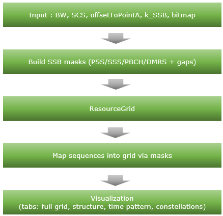
Inputs: Channel BW, SSB SCS (case A–E), raster params (offsetToPointA, k_SSB), SSB TX bitmap, active SSB indices/positions.
-
Masks: Construct PSS, SSS, PBCH, PBCH DMRS masks with SSB-specific gaps (Symbol 2 gaps at SC 48–55 and 183–191).
-
ResourceGrid (sionna.phy.ofdm.ResourceGrid): Defines the OFDM grid (4 symbols, 240 subcarriers) to place the SSB.
-
Mapping: Sequences (PSS/SSS BPSK, PBCH/DMRS QPSK) are inserted into the grid using the masks.
-
Visualization: Tkinter tabs render full grid, structure diagram, time pattern, and constellations (PSS/SSS/PBCH/DMRS/combined).
Toolkits for the script
I didn't write the code myself. What I did was just prompting for AI tool and did basic check up for the output. Followings are the tool kits that I used for this script
- Scripting IDE : Cursor
- Version: 2.1.50 (system setup)
- VSCode Version: 1.105.1
- Commit: 56f0a83df8e9eb48585fcc4858a9440db4cc7770
- Date: 2025-12-06T23:39:52.834Z
- Electron: 37.7.0
- Chromium: 138.0.7204.251
- Node.js: 22.20.0
- V8: 13.8.258.32-electron.0
- OS: Windows_NT x64 10.0.26100
- AI Model : Opus 4.5 (as of Dec 8, 2025) and GPT 5.1 Codex Max(as of Dec 8, 2025)
- Python Info : Check out this note for the detailed installation proces that I went through
|
==== Python Version ====
3.12.3 (main, Nov 6 2025, 13:44:16) [GCC 13.3.0]
==== Python Executable ====
/home/jaeku/nvidia/venv-sionna/bin/python3
==== Platform Info ====
Linux-6.6.87.2-microsoft-standard-WSL2-x86_64-with-glibc2.39
('main', 'Nov 6 2025 13:44:16')
==== Site-Packages Directories ====
['/home/jaeku/nvidia/venv-sionna/lib/python3.12/site-packages', '/home/jaeku/nvidia/venv-sionna/local/lib/python3.12/dist-packages', '/home/jaeku/nvidia/venv-sionna/lib/python3/dist-packages', '/home/jaeku/nvidia/venv-sionna/lib/python3.12/dist-packages']
==== sys.path ====
/home/jaeku/nvidia
/usr/lib/python312.zip
/usr/lib/python3.12
/usr/lib/python3.12/lib-dynload
/home/jaeku/nvidia/venv-sionna/lib/python3.12/site-packages
==== Installed Packages ====
absl-py == 2.3.1
asttokens == 3.0.1
astunparse == 1.6.3
certifi == 2025.11.12
charset-normalizer == 3.4.4
comm == 0.2.3
contourpy == 1.3.3
cycler == 0.12.1
decorator == 5.2.1
drjit == 1.2.0
executing == 2.2.1
flatbuffers == 25.9.23
fonttools == 4.61.0
gast == 0.7.0
google-pasta == 0.2.0
grpcio == 1.76.0
h5py == 3.15.1
idna == 3.11
importlib_resources == 6.5.2
ipydatawidgets == 4.3.5
ipython == 9.8.0
ipython_pygments_lexers == 1.1.1
ipywidgets == 8.1.8
jedi == 0.19.2
jupyterlab_widgets == 3.0.16
keras == 3.12.0
kiwisolver == 1.4.9
libclang == 18.1.1
Markdown == 3.10
markdown-it-py == 4.0.0
MarkupSafe == 3.0.3
matplotlib == 3.10.7
matplotlib-inline == 0.2.1
mdurl == 0.1.2
mitsuba == 3.7.1
ml_dtypes == 0.5.4
namex == 0.1.0
numpy == 1.26.4
opt_einsum == 3.4.0
optree == 0.18.0
packaging == 25.0
parso == 0.8.5
pexpect == 4.9.0
pillow == 12.0.0
pip == 25.3
prompt_toolkit == 3.0.52
protobuf == 6.33.2
ptyprocess == 0.7.0
pure_eval == 0.2.3
Pygments == 2.19.2
pyparsing == 3.2.5
python-dateutil == 2.9.0.post0
pythreejs == 2.4.2
requests == 2.32.5
rich == 14.2.0
scipy == 1.16.3
setuptools == 80.9.0
sionna == 1.2.1
sionna-rt == 1.2.1
six == 1.17.0
stack-data == 0.6.3
tensorboard == 2.20.0
tensorboard-data-server == 0.7.2
tensorflow == 2.20.0
termcolor == 3.2.0
traitlets == 5.14.3
traittypes == 0.2.3
typing_extensions == 4.15.0
urllib3 == 2.6.0
wcwidth == 0.2.14
Werkzeug == 3.1.4
wheel == 0.45.1
widgetsnbextension == 4.0.15
wrapt == 2.0.1
|
Source Code and Output
You can get the source code for this note here. I would not describe / explain on every single line of the code since AI (e.g, chatGPT, Gemini etc) will explain better than I do.
Disclaimer !!!
I have checked and fixed some obvious issues of the script while I am prompting the script, but I haven't verified all the details of the implementation. So there likely to be bugs / errors that I missed. So take this purely as an educational purpose for getting some high level idea on how 3GPP NR Phy specification can be implemented
The script output some part of the result in text and some part in graphics.
Followings are the output of the code in text
|
2025-12-08 17:23:55.539729: I external/local_xla/xla/tsl/cuda/cudart_stub.cc:31] Could not find cuda drivers on your machine, GPU will not be used.
2025-12-08 17:23:55.553756: I tensorflow/core/util/port.cc:153] oneDNN custom operations are on. You may see slightly different numerical results due to floating-point round-off errors from different computation orders. To turn them off, set the environment variable `TF_ENABLE_ONEDNN_OPTS=0`.
2025-12-08 17:23:56.099971: I tensorflow/core/platform/cpu_feature_guard.cc:210] This TensorFlow binary is optimized to use available CPU instructions in performance-critical operations.
To enable the following instructions: AVX2 AVX_VNNI FMA, in other operations, rebuild TensorFlow with the appropriate compiler flags.
2025-12-08 17:23:57.903978: I tensorflow/core/util/port.cc:153] oneDNN custom operations are on. You may see slightly different numerical results due to floating-point round-off errors from different computation orders. To turn them off, set the environment variable `TF_ENABLE_ONEDNN_OPTS=0`.
2025-12-08 17:23:57.906758: I external/local_xla/xla/tsl/cuda/cudart_stub.cc:31] Could not find cuda drivers on your machine, GPU will not be used.
======================================================================
SSB Resource Grid Configuration
======================================================================
SSB Case: B
SSB Subcarrier Spacing: 30 kHz
L_max: 8
SSB TX Bitmap: 11111111
SSBs Transmitted: 8
SSB Symbol Positions: [4, 8, 16, 20, 32, 36, 44, 48]
SSB Indices (bitmap): [0, 1, 2, 3, 4, 5, 6, 7]
offsetToPointA (RB@15k): 92
k_SSB (SC@15k): 0
----------------------------------------------------------------------
Channel Bandwidth: 50 MHz
Max RBs in Channel: 133
FFT Size: 4096
Guard Carriers: 1250 (left), 1250 (right)
----------------------------------------------------------------------
Half Frame Duration: 5.0 ms
Slot Duration: 0.5 ms
Slots in Half Frame: 10
Total OFDM Symbols: 140
----------------------------------------------------------------------
SSB Size: 20 RBs x 4 symbols
SSB Offset (RB): 46
SSB Start Subcarrier: 552
----------------------------------------------------------------------
Cell ID: 0
N_ID^(1): 0
N_ID^(2): 0
======================================================================
SSB Resource Element Statistics:
PSS REs: 1016
SSS REs: 1016
PBCH REs: 3456
PBCH DMRS REs: 1152
Total SSB REs: 6640
REs per SSB: 960
======================================================================
SSB Configuration Summary
======================================================================
SSB Case: B
Subcarrier Spacing: 30 kHz
L_max: 8
SSB TX Bitmap: 11111111
SSBs Transmitted: 8
SSB Starting Symbols: [4, 8, 16, 20, 32, 36, 44, 48]
SSB Indices (bitmap order): [0, 1, 2, 3, 4, 5, 6, 7]
offsetToPointA (RB@15k): 92
k_SSB (SC@15k): 0
----------------------------------------------------------------------
Time Domain:
Half Frame Duration: 5.0 ms
Slots in Half Frame: 10
Symbols per Slot: 14
Total Symbols (5ms): 140
----------------------------------------------------------------------
Frequency Domain:
Channel Bandwidth: 50 MHz
Max RBs in Channel: 133
SSB Size: 20 RBs (240 subcarriers)
SSB Start RB: 46
SSB Start Subcarrier: 552
----------------------------------------------------------------------
SSB Components (per burst):
PSS: 127 subcarriers (Symbol 0)
SSS: 127 subcarriers (Symbol 2)
PBCH: 3 symbols with DMRS (every 4th SC)
|
Followings are the snapshots of graphical output (NOTE : If you want to get images for better resolution, I would suggest you to install the sionna on your PC and run the script that I shared).
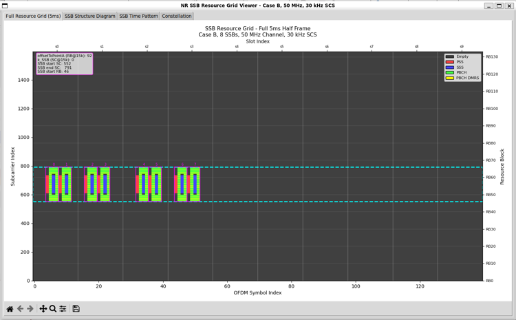
Full Resource Grid
NR SSB resource grid visualization for Case B, 50 MHz channel bandwidth, 30 kHz subcarrier spacing, shown over a 5 ms half-frame.
Followings are the brief descriptions on each components of the plot
- Horizontal axis (time): OFDM symbol index across the half-frame. Only specific symbol ranges contain energy, so this confirms that SSBs are transmitted in discrete symbol locations, not continuously.
- SSB instances: Repeated blocks in time correspond to active SSB indices enabled by the SSB bitmap. The small numbers above each block indicate the SSB index within the SS burst set.
- Vertical axis (frequency): Subcarrier index of the full carrier grid. Most of the grid is empty, so you can see that SSB occupies only a small part of the full carrier.
- SSB bandwidth: The dashed horizontal lines mark the 240 consecutive subcarriers used by each SSB, so it clearly shows how narrow the SSB is relative to the 50 MHz channel.
- Frequency positioning: The absolute vertical placement of the SSB region is determined by offsetToPointA and kSSB, which fix the SSB location with respect to Point A.
- Internal SSB structure: Within each SSB block, different colors represent PSS, SSS, PBCH, and PBCH DMRS, arranged according to the fixed 4-symbol × 240-subcarrier SSB pattern.
- PBCH DMRS pattern: The interleaved DMRS REs inside the PBCH region confirm that DMRS masking and mapping are applied correctly.
- Empty REs: All non-SSB REs remain zero, so this highlights the implementation approach: create the full resource grid first, then map SSB content selectively via masks.
- Overall validation: This figure validates time placement, frequency placement, and internal SSB structure for the configured Case B SSB transmission.
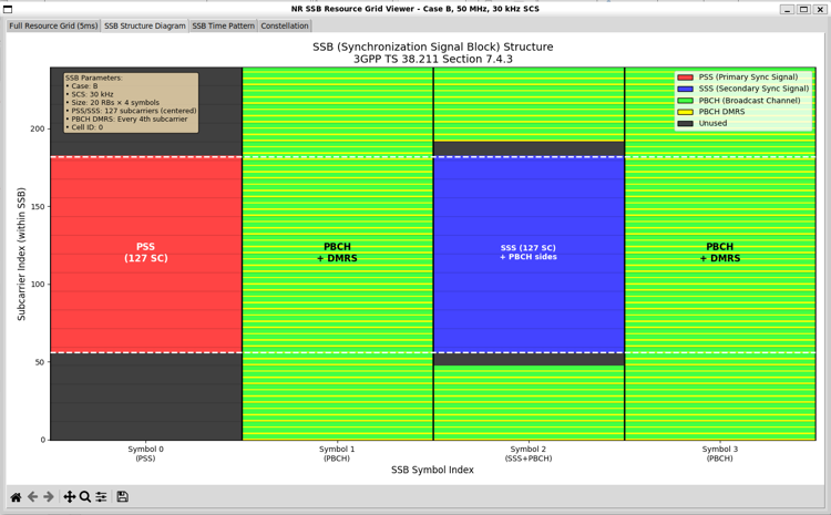
SSB Structure
One SSB spans 4 consecutive OFDM symbols in time and 240 subcarriers in frequency. This view zooms into that 4-symbol × 240-subcarrier region.
Followings are the brief descriptions on each components of the plot
- Vertical axis: Subcarrier index within the SSB. Only the SSB-local frequency range is shown, not the full carrier.
- Horizontal axis: SSB symbol index from Symbol 0 to Symbol 3, corresponding to the four OFDM symbols that form a single SSB.
- Symbol 0 (PSS): The Primary Synchronization Signal occupies 127 consecutive subcarriers, centered within the 240-subcarrier SSB bandwidth. Remaining subcarriers are unused.
- Symbol 1 (PBCH): This symbol carries PBCH data with PBCH DMRS interleaved in frequency. DMRS appears on every fourth subcarrier, enabling channel estimation for PBCH.
- Symbol 2 (SSS + PBCH): The Secondary Synchronization Signal occupies 127 subcarriers in the center. PBCH data continues on both sides of the SSS region, following the 3GPP-defined layout.
- Symbol 3 (PBCH): PBCH transmission continues, again with PBCH DMRS interleaved across frequency in a fixed pattern.
- Color coding: Distinct colors indicate PSS, SSS, PBCH, PBCH DMRS, and unused REs, making the internal SSB composition visually explicit.
- DMRS pattern: PBCH DMRS is placed at fixed subcarrier offsets, repeating every fourth subcarrier, which matches the specification and validates correct mask generation.
- Center alignment: Both PSS and SSS are centered within the SSB bandwidth, confirming correct frequency centering independent of the SSB’s absolute position in the carrier.
- Specification compliance: The layout exactly matches 3GPP TS 38.211 Section 7.4.3, verifying that symbol usage and frequency allocation are implemented correctly.
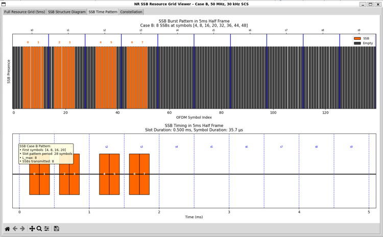
SSB Time Pattern
This view illustrates the time-domain transmission pattern of SSBs within a 5 ms half-frame for Case B.
Followings are the brief descriptions on each components of the plot
- Upper panel (OFDM-symbol view): The horizontal axis shows the OFDM symbol index across the half-frame. Orange regions indicate symbols carrying SSBs, while dark regions indicate empty symbols.
- SSB grouping: SSB symbols appear in clusters, reflecting the fact that each SSB occupies 4 consecutive OFDM symbols.
- SSB indices: Numbers above the orange clusters correspond to the SSB index within the SS burst set, as defined by the Case B pattern.
- Active symbols: For Case B, SSBs are transmitted at symbol indices {4, 8, 16, 20, 32, 36, 44, 48}, which matches the highlighted regions.
- Empty symbols: Large gaps between clusters show that no SSB energy is transmitted during most OFDM symbols in the half-frame.
- Lower panel (time-in-ms view): The horizontal axis is expressed in time (ms), making it easier to relate SSB transmission to frame timing.
- Slot boundaries: Vertical dashed lines indicate slot boundaries. Each slot duration is approximately 0.5 ms for 30 kHz SCS.
- SSB burst duration: The orange blocks at the beginning of the half-frame show that the SSB burst is confined to an early time window, followed by a long idle period.
- Case B characteristic: The pattern reflects a medium SCS (30 kHz) deployment where SSBs are denser than Case A but still limited to a specific burst region.
- Bitmap relationship: Which of these potential SSB locations are actually transmitted is controlled by the SSB bitmap, which enables or disables individual SSB indices.
- Design implication: This visualization confirms that the implementation correctly separates time-pattern generation from frequency-domain grid mapping.
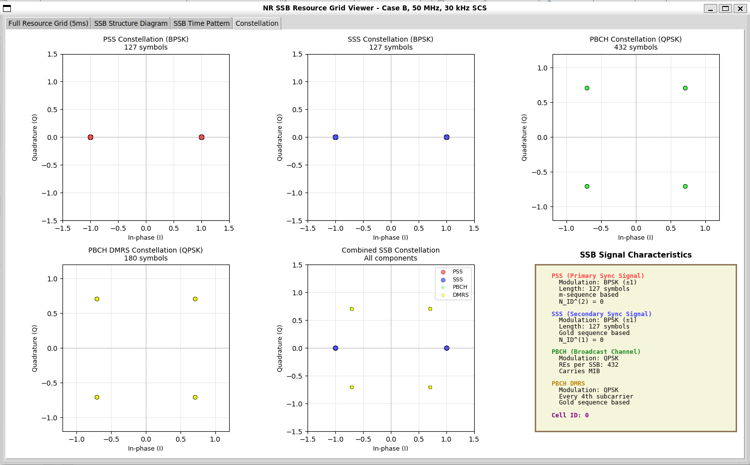
Constellation
This panel verifies that each SSB component is mapped using the correct modulation scheme and that the generated symbols fall on the expected constellation points.
Followings are the brief descriptions on each components of the plot
- PSS constellation: The Primary Synchronization Signal uses BPSK modulation. The plot shows 127 symbols located at ±1 on the in-phase axis, with zero quadrature component, confirming correct BPSK mapping.
- SSS constellation: The Secondary Synchronization Signal also uses BPSK modulation with 127 symbols. The constellation points mirror the PSS behavior but are generated from a different sequence definition.
- PBCH constellation: The Broadcast Channel uses QPSK modulation. The plot shows 432 symbols evenly distributed over the four QPSK constellation points.
- PBCH DMRS constellation: PBCH DMRS also uses QPSK. The plot contains 180 symbols, showing clean clustering at the four ideal QPSK points, which confirms correct reference-signal generation.
- Combined SSB constellation: This plot overlays PSS, SSS, PBCH, and PBCH DMRS symbols together. BPSK points from PSS/SSS and QPSK points from PBCH/DMRS coexist without distortion, confirming correct multiplexing.
- Symbol counts: The number of plotted symbols for each component matches the expected counts defined by 3GPP TS 38.211, validating correct RE allocation and masking.
- Amplitude normalization: All constellations are centered and properly normalized, indicating that no unintended scaling or phase rotation has been applied.
- Cell ID dependence: PSS, SSS, and PBCH DMRS symbol sequences are generated based on the configured cell ID, which affects the exact symbol ordering but not the constellation geometry.
- Implementation check: This view acts as a final sanity check that sequence generation, modulation, and grid mapping are consistent before OFDM modulation or channel processing.
Source Code Overview
Even though I no longer need to describe every single line of code in the age of AI, I still think it is valuable to write down some key points. This is not to show off the code itself. It is to record the intention behind the script. I want to clarify what I was trying to do, what kind of idea I had in mind, and what kind of problems this script is designed to solve. This allows the reader to connect the final result with the original design goal. It also helps me later when I come back to
this code after a long time and forget my own thinking process.
You may not need all of these details if your only goal is to understand the output of the script. For simple usage, you can often treat the script as a black box. You run it. You look at the result. You move on. In many cases this is enough. However, if you want to modify, revise, or extend the script for your own purpose, the situation changes. You would need to know which part of the code is doing what. You would need to know which parameters control which behavior. You would also need to
know what kind of assumptions I made when I first wrote the code. In that case, a clear description of the code is not a luxury. It becomes a kind of map.
One of the best ways to learn anything related to programming is still very old-fashioned. You break it and then you fix it. You change a small part of the script and see what goes wrong. You check the error. You adjust. You run it again. This loop may look inefficient at first, but it forces your brain to connect cause and effect inside the code. So my intention with these explanations is not just to document the script. It is to give you enough context so that you can safely break it, understand
why it broke, and then fix it in a way that matches your own idea. This process is painful sometimes, but it is also the part that makes the knowledge stick to your brain.
Key Features
- SSB Grid Generation: 4-symbol SSB (20 RBs, 240 subcarriers), PSS/SSS centered, PBCH + DMRS, unused gaps in Symbol 2.
- Auto Positioning: Computes
offsetToPointA / k_SSB to center SSB for any CBW/SCS; clamps if needed.
- Bitmap-Controlled Bursts:
SSB_TX_BITMAP selects which SSB indices (0..L_max-1) transmit.
- Case Support: Cases A–E with correct SCS and symbol patterns per 38.213.
- Visualization Tabs: Full grid (with frequency annotations), SSB structure diagram, time pattern, constellations (PSS/SSS/PBCH/DMRS + combined).
What is Implemented ?
Followings are the features that I fully implemented (hopefully :)
|
Feature
|
Description
|
Reference
|
|
SSB structure
|
4 symbols, PSS/SSS centered, PBCH+DMRS, unused gaps in Symbol 2
|
TS 38.211 §7.4.3
|
|
Positioning
|
Auto-centered offsetToPointA / k_SSB on 15 kHz raster; SSB start RB/SC derived
|
TS 38.213
|
|
Cases A–E
|
Correct SCS and symbol patterns
|
TS 38.213 §4.1
|
|
Bitmap control
|
SSB_TX_BITMAP selects active SSB indices (0..L_max-1)
|
TS 38.213
|
|
Constellations
|
PSS/SSS (BPSK), PBCH/DMRS (QPSK), combined plot
|
TS 38.211
|
|
GUI Tabs
|
Full grid, SSB structure diagram, time pattern, constellation
|
-
|
What is NOT Implemented ?
|
Feature
|
Description
|
Reference
|
|
CSI-RS, PTRS sequences
|
Not modeled (only DMRS for PBCH)
|
TS 38.211
|
|
SSB scrambling sequences
|
Uses simplified sequences (random/QPSK for PBCH/DMRS)
|
TS 38.211
|
|
Multi-beam/multi-PCI
|
Single PCI (N_CELL_ID) at a time
|
TS 38.211
|
|
FR2 k_SSB finer offsets
|
Uses 15 kHz raster; FR2 finer raster not modeled
|
TS 38.213
|
|
PBCH channel coding
|
No PBCH BCH/MIB channel coding; symbols are uncoded QPSK
|
TS 38.212
|
Description of Parameters (Global Variables)
SSB Case and Counts
|
Param
|
Default
|
Description
|
|
SSB_CASE
|
'B'
|
Case A–E
|
|
L_MAX
|
8
|
Max SSBs per half-frame (per case)
|
|
SSB_TX_BITMAP
|
'11111111'
|
Bitmap of SSB presence (len ≤ L_MAX)
|
Channel / Raster
|
Param
|
Default
|
Description
|
|
CHANNEL_BW_MHZ
|
50
|
Channel bandwidth
|
|
SSB_SCS_KHZ
|
case-based
|
SSB SCS (15/30/120/240)
|
|
COMMON_SCS_KHZ
|
15
|
Common raster for offset/k_SSB
|
Derived Positioning
|
Derived
|
Description
|
|
OFFSET_TO_POINTA_RB
|
RB offset on 15 kHz raster (auto-centered)
|
|
K_SSB
|
Subcarrier offset on 15 kHz raster
|
|
SSB_START_SC, SSB_OFFSET_RB
|
Start SC/RB at SSB SCS
|
Physical Layout
|
Param
|
Value
|
Description
|
|
SSB_NUM_RBS
|
20
|
240 subcarriers
|
|
SSB_NUM_SYMBOLS
|
4
|
Symbols 0–3
|
|
PSS_SSS_START_SC
|
56
|
PSS/SSS start (within SSB)
|
|
PSS_SSS_NUM_SUBCARRIERS
|
127
|
PSS/SSS length
|
|
PBCH_LEFT_END_SC
|
48
|
PBCH left edge (0–47)
|
|
PBCH_RIGHT_START_SC
|
192
|
PBCH right edge (192–239)
|
Time
|
Derived
|
Description
|
|
NUM_SLOTS_IN_HALF_FRAME
|
Half-frame slots (depends on SCS)
|
|
NUM_OFDM_SYMBOLS
|
Slots × 14
|
Description of Functions
Positioning
-
Centering logic (inline): computes OFFSET_TO_POINTA_RB / K_SSB on 15 kHz raster to place SSB in the middle of CBW, then derives SSB_START_SC / SSB_OFFSET_RB at the SSB SCS. Clamps if needed.
-
Bitmap helpers: normalize_ssb_bitmap, apply_ssb_bitmap build SSB_ACTIVE = list of (ssb_index, symbol_position) honoring the bitmap bits (0/1) up to L_MAX.
SSB Sequences
- generate_pss_sequence(n_id_2): PSS m-sequence (BPSK).
- generate_sss_sequence(n_id_1, n_id_2): SSS m-sequences (BPSK).
- generate_pbch_dmrs_sequence(n_cell_id, ssb_index, l_ssb_max): Simplified PBCH DMRS (QPSK, uncoded).
- PBCH data: uncoded random QPSK (no BCH/MIB channel coding).
Masks and Grid
-
get_ssb_symbol_positions(ssb_case, num_ssb, l_max): Returns list of start symbols per case A–E (38.213).
Params: ssb_case (str), num_ssb (int), l_max (int).
-
create_ssb_masks(num_symbols, num_subcarriers, ssb_start_sc, ssb_symbol_positions): Builds PSS/SSS/PBCH/PBCH-DMRS/combined masks with gaps in Symbol 2 (48-55, 183-191).
Params: num_symbols (int), num_subcarriers (int), ssb_start_sc (int), ssb_symbol_positions (list).
-
create_resource_grid_display(num_symbols, num_subcarriers, ssb_masks): Encodes masks into numeric grid for plotting.
Params: num_symbols (int), num_subcarriers (int), ssb_masks (dict of masks).
Sionna APIs Used
-
sionna.phy.ofdm.ResourceGrid: OFDM grid definition (FFT, SCS, guards, pilot pattern).
Params: num_ofdm_symbols, fft_size, subcarrier_spacing, num_tx, num_streams_per_tx, cyclic_prefix_length, pilot_pattern, num_guard_carriers, dc_null.
-
sionna.phy.ofdm.ResourceGridMapper: Maps data/pilots into grid.
Params: resource_grid.
-
sionna.phy.ofdm.PilotPattern: Pilot masks/values (DMRS; PSS/SSS/PBCH via masks).
Params: mask, pilots, normalize.
-
sionna.phy.mapping.BinarySource: Generates random bits.
Params: shape [batch, num_tx, num_streams, num_bits].
-
sionna.phy.mapping.Mapper: Maps bits to QAM/QPSK.
Params: modulation (e.g., "qam"), num_bits_per_symbol.
Visualization (Tabbed GUI)
- Tab 1: Full grid (with offsetToPointA/k_SSB box, SSB region box, slot/RB labels).
- Tab 2: SSB structure diagram (PBCH/DMRS/SSS layout with gaps).
- Tab 3: Time pattern (burst timeline, slot labels).
- Tab 4: Constellations (PSS, SSS, PBCH, DMRS, combined + info box).
|
|