Beam failure recovery is a critical mechanism in 5G networks designed to ensure seamless connectivity and reliability, even in challenging radio conditions. This procedure addresses situations where the signal strength of the connected beam drops below a predefined threshold, indicating beam failure. When such an event occurs, the UE initiates a recovery process by detecting beam failure using a specific reference signal and searching for a candidate beam with better signal quality. If a sufficient number of beam failures are detected, the UE triggers the beam failure recovery process by transmitting a request to the network using a PRACH preamble linked to the candidate beam. The network then responds with the necessary configuration, completing the recovery process and re-establishing a reliable connection. This process ensures that the UE can maintain continuous communication with the network, even in dynamic or high-mobility scenarios where beam quality may vary rapidly.
Followings are the topics I am going to look into in this note
- What exactly counts as a beam failure ?
- How the counter and the timer work together
- Which reference signals does the UE actually monitor ?
- Who does what : PHY, MAC and the network
- RRC Parameters for Beam Failure Detection
- RRC Parameters for Beam Failure Recovery Configuration
- SCell Beam Failure Recovery (Release 16)
- Examples
- Example 01 : Hand blockage on a mmWave phone (the textbook case)
- Example 02 : Walking around a street corner (LoS lost, reflection found)
- Example 03 : A truck passes by (the case where BFR should NOT trigger)
- Example 04 : Rotating the device / raising the phone to the ear
- Example 05 : No candidate beam is found - BFR fails and RLF follows
- Example 06 : Beam failure on an SCell in Carrier Aggregation (Release 16)
- Example 07 : A fixed wireless access CPE and a tree in the wind
- Summary of the scenarios
Beam Failure detection and recovery procedure is specified in 38.321-5.17 and can be summarized as below.
|
Step |
Direction |
Process |
|
1 |
< UE > |
Detects Beam Failure (L1-RSRP for the connected beam goes below a certain limit). UE uses a specific Reference Signal to detect the beam failure. |
|
2 |
< UE > |
Search Another Canadidate Beam with good quality |
|
3 |
UE -> NW |
If a predefined number of Beam Failure is detected, Trigger Beam Failure Recovery Process with the candidate beam (PRACH). The predefined number of beamfailure to trigger this process is defined by beamFailureInstanceMaxCount in RRC. // UE send PRACH with the ID specified in BFR-SSB-Resource.ra-PreambleIndex |
|
4 |
UE <- NW |
Reply to Beam Failure Recovery Request (RACH Response). NW send DCI for msg2 via the search space specified by recoverySearchSpaceId |
This process is illustrated as below from this paper([3])
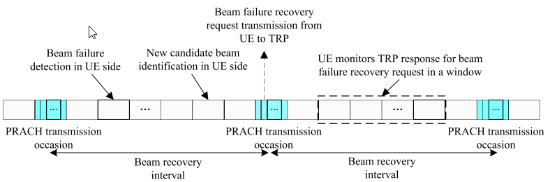
Following is breakdown of the illustration :
-
Beam Failure Detection : The process starts with the UE detecting a beam failure. This occurs when the signal strength of the connected beam, typically measured using L1-RSRP or a reference signal, falls below a predefined threshold. -
Candidate Beam Identification : After detecting the beam failure, the UE searches for a new candidate beam with better signal quality. This involves scanning the available beams in the network and selecting one that meets the required quality criteria. -
Beam Failure Recovery Request : -
The UE sends a Beam Failure Recovery Request to the network using the Physical Random Access Channel (PRACH).
-
In Release 15, PRACH is used for recovery requests in the primary cell.
-
In Release 16, uplink control channels are also supported for recovery requests in secondary cells during carrier aggregation.
-
The use of non-contention-based PRACH ensures faster and more reliable message delivery for critical beam recovery scenarios.
-
Network Response : The network (via the Transmission Reception Point, TRP) monitors and responds to the recovery request. This response includes acknowledgment or configuration details to establish communication using the newly identified beam. -
Post-Recovery Communication : After the recovery process, the UE and TRP switch to the newly identified beam(s) for ongoing communication. This ensures that the connection remains robust and uninterrupted.
To accelerate the procedure of beam recovery and ensure the robustness of this message delivery, non-contention based channel based on physical random access channel (PRACH) (instead of contention-based) can be used for carrying beam failure recovery request for primary cell in Release 15. In Release 16, uplink control channel is additionally supported for carrying beam failure recovery request for secondary cells in the case of carrier aggregation. After this beam failure recovery process, the TRP and UE can use the newly identified beam(s) for subsequent communication
- The non-contention-based PRACH mechanism significantly accelerates the beam recovery process and ensures reliable delivery of recovery requests, especially in challenging environments.
- The enhancements in Release 16, including support for secondary cells in carrier aggregation, make beam recovery more versatile in advanced network configurations.
- This process is critical in scenarios involving high mobility, interference, or complex beamforming setups, enabling seamless communication and improving user experience.
What exactly counts as a beam failure ?
The summary above says the beam quality drops below a threshold, and that is the right idea. But if you go looking for that threshold in the specification you will not find an RSRP value, and it is worth knowing why.
The physical layer does not compare RSRP against a limit. It estimates the radio link quality of each beam failure detection reference signal, the BFD-RS, and compares it against a threshold called Qout,LR. And Qout,LR is not defined in dBm at all. It is defined as the point at which the
The word hypothetical is doing real work there. There may be no PDCCH being transmitted on that beam at that moment. What the UE works out is what the block error rate
Why go to that trouble instead of just using RSRP ? Because RSRP knows nothing about interference. A beam can be strong and still be undecodable, if something else is arriving on top of it. What actually matters is whether the UE can still receive control information. So the criterion is written in terms of control channel decoding rather than received power.
There is a second detail that catches people, and it changes how the feature behaves in the field. A beam failure instance is only counted when
The candidate side has its own threshold and it works the other way round. A candidate beam only counts as usable if it is above Qin,LR. The RRC parameter that carries that value is rsrp-ThresholdSSB for the SpCell, or rsrp-ThresholdBFR-r16 for an SCell.
How the counter and the timer work together
This is the part of 38.321 that is most often misread, and it is worth going through slowly. There are exactly two pieces of state : a counter called BFI_COUNTER and a timer called beamFailureDetectionTimer.
The rule is short. Every time the physical layer reports a beam failure instance, MAC does two things. It restarts the timer, and it adds one to the counter. If the counter reaches beamFailureInstanceMaxCount, beam failure is declared. If the timer expires first, the counter is set back to zero.
Read that once more and notice the word restarts. The timer is not started once at the first bad instance and left to run. It is restarted at every bad instance. So the counter can only climb while bad instances keep arriving
That single design choice is what makes the feature usable. Without it, a UE that saw one bad instance every few seconds would eventually accumulate enough of them to declare a failure. The link would have been perfectly healthy the whole time. With it, only a genuine sustained loss gets through.
Two practical consequences follow, and both of them matter when you are tuning a network.
The units are periods, not milliseconds : beamFailureDetectionTimer is expressed as pbfd1 through pbfd10, and those are multiples of the BFD-RS period. So the same setting behaves very differently with a 10 ms CSI-RS than with an 80 ms one. You cannot read the timer without knowing the reference signal period.The pair sets the reaction time : the fastest possible declaration is beamFailureInstanceMaxCount multiplied by the BFD-RS period. With n3 and a 10 ms period that is 30 ms. Lower the count or shorten the period and the UE reacts faster, at the price of more false triggers.
Which reference signals does the UE actually monitor ?
Everything above depends on the BFD-RS set, so the obvious next question is where that set comes from. There are two answers, and in a live network the second one is the common case.
The explicit answer is the one you see in the ASN.1 below. The network lists the resources in failureDetectionResourcesToAddModList, inside RadioLinkMonitoringConfig, and each entry carries a purpose field set to beamFailure, rlf or both. Up to ten resources can be configured, since maxNrofFailureDetectionResources is 10.
The implicit answer applies when the network configures none of them, and this is where it gets elegant. In that case the UE derives the set itself, from the TCI states of the CORESETs it is monitoring for PDCCH. Specifically it takes the reference signal that provides QCL-TypeD in each active TCI state, and it uses up to two of them.
Think about what that means. The UE ends up monitoring exactly the beams that its control channel is arriving on. Not a beam the network guessed might be relevant, but the actual beam whose failure would stop the UE being reachable. The set also follows the beam automatically, because every time the CORESET TCI state is updated the BFD-RS set moves with it.
Who does what : PHY, MAC and the network
The four step table near the top gives the outline. It is worth redrawing it with the layer boundaries shown. Almost every confusing question about beam failure recovery turns out to be a question about which layer owns which decision.
Three things in that picture are worth calling out.
The physical layer never declares anything : it only reports instances. It has no counter and no memory of previous instances. All of the decision logic sits in MAC, which is why the procedure is specified in 38.321 rather than in a physical layer specification.The PRACH carries no payload : there is no message that says 'my beam failed, please use SSB #5'. The UE simply transmits the preamble that was reserved for SSB #5, on the occasion reserved for it. The network works out both facts from where the preamble arrived. This is the same trick used at initial access, and it is the reason recovery can work when there is no usable grant.Recovery is contention free when it can be : candidateBeamRSList may give a dedicated ra-PreambleIndex for the candidate. When it does, the UE uses it and skips contention resolution entirely. That is what makes recovery fast enough to be worth having.
The last box in the diagram is the one people forget. Beam failure recovery is allowed to fail. If beamFailureRecoveryTimer expires, or the UE runs out of preamble attempts at preambleTransMax, the random access procedure is unsuccessful. That outcome is what eventually drives radio link failure. Beam failure recovery is a repair mechanism, not a guarantee. Example 05 below walks through exactly that case.
RRC Parameters for Beam Failure Detection
The RRC Parameters for Beam Failure Detection define the configuration used by the UE to monitor and detect beam failures in 5G networks. These parameters are part of the RRC signaling protocol and specify how the UE should identify and handle beam failure scenarios.
Followings are key concepts of this RRC parameter :
Dynamic Configuration : The configuration allows the network to dynamically add, modify, or release monitoring resources to adapt to changing conditions in the network.Beam Failure Detection : The UE monitors the signal quality of reference signals (SSB or CSI-RS) and compares it to predefined thresholds. If the quality drops below the threshold for a specific duration (defined by beamFailureDetectionTimer), a beam failure is detected.Flexible Monitoring : The configuration supports different use cases, including monitoring for beam failures (beamFailure), radio link failures (rlf), or both simultaneously.Network Control : These parameters are provided by the network to ensure efficient and precise monitoring, minimizing false alarms and optimizing recovery procedures
RadioLinkMonitoringConfig ::= SEQUENCE { failureDetectionResourcesToAddModList SEQUENCE (SIZE(1..maxNrofFailureDetectionResources)) OF RadioLinkMonitoringRS OPTIONAL, -- Need N failureDetectionResourcesToReleaseList SEQUENCE (SIZE(1..maxNrofFailureDetectionResources)) OF RadioLinkMonitoringRS-Id OPTIONAL, -- Need N beamFailureInstanceMaxCount ENUMERATED {n1, n2, n3, n4, n5, n6, n8, n10} OPTIONAL, -- Need R beamFailureDetectionTimer ENUMERATED {pbfd1, pbfd2, pbfd3, pbfd4, pbfd5, pbfd6, pbfd8, pbfd10} OPTIONAL, -- Need R ... }RadioLinkMonitoringRS ::= SEQUENCE { radioLinkMonitoringRS-Id RadioLinkMonitoringRS-Id, purpose ENUMERATED {beamFailure, rlf, both}, detectionResource CHOICE { ssb-Index SSB-Index, csi-RS-Index NZP-CSI-RS-ResourceId }, ... } RadioLinkMonitoringRS-Id ::= INTEGER (0..maxNrofFailureDetectionResources-1) maxNrofFailureDetectionResources INTEGER ::= 10
- A sequence that defines the list of resources to add or modify for beam failure detection.
- Each entry in this list corresponds to a RadioLinkMonitoringRS, which contains the details of a specific reference signal used for monitoring beam failure.
- A sequence that defines the list of resources to be released, corresponding to previously configured monitoring resources.
- This allows the network to dynamically update the monitoring configuration by removing obsolete resources.
- An enumerated parameter that specifies the maximum number of beam failures that the UE can tolerate before triggering the recovery procedure.
- Possible values include predefined counts such as n1, n2, n3, n4, n5, n6, n8, n10.
- An enumerated timer that defines the maximum time duration for monitoring and detecting beam failures.
- The timer values include pbfd1, pbfd2, pbfd3, pbfd4, pbfd5, pbfd6, pbfd8, pbfd10, where "pbfd" refers to "Physical Beam Failure Detection."
RRC Parameters for Beam Failure Recovery Configuration
The RRC Parameters for Beam Failure Recovery Configuration specify the configuration for managing beam failure recovery in 5G networks. These parameters define how the UE (User Equipment) interacts with the network to re-establish communication when a beam failure occurs.
BeamFailureRecoveryConfig ::= SEQUENCE { rootSequenceIndex-BFR INTEGER (0..137) OPTIONAL, -- Need M rach-ConfigBFR RACH-ConfigGeneric OPTIONAL, -- Need M rsrp-ThresholdSSB RSRP-Range OPTIONAL, -- Need M candidateBeamRSList SEQUENCE (SIZE(1..maxNrofCandidateBeams)) OF PRACH-ResourceDedicatedBFR OPTIONAL, -- Need M ssb-perRACH-Occasion ENUMERATED {oneEighth, oneFourth, oneHalf, one, two, four, eight, sixteen} OPTIONAL, -- Need M ra-ssb-OccasionMaskIndex INTEGER (0..15) OPTIONAL, -- Need M recoverySearchSpaceId SearchSpaceId OPTIONAL, -- Need R ra-Prioritization RA-Prioritization OPTIONAL, -- Need R beamFailureRecoveryTimer ENUMERATED {ms10, ms20, ms40, ms60, ms80, ms100, ms150, ms200} OPTIONAL, -- Need M ..., [[ msg1-SubcarrierSpacing SubcarrierSpacing OPTIONAL -- Need M ]], [[-- added in Release 16 ra-PrioritizationTwoStep-r16 RA-Prioritization OPTIONAL, -- Need R candidateBeamRSListExt-v1610 SetupRelease { CandidateBeamRSListExt-r16 } OPTIONAL -- Need M ]] }CandidateBeamRSListExt-r16 ::= SEQUENCE (SIZE(1..maxNrofCandidateBeamsExt-r16)) OF PRACH-ResourceDedicatedBFR maxNrofCandidateBeams INTEGER ::= 16 maxNrofCandidateBeamsExt-r16 INTEGER ::= 48
PRACH-ResourceDedicatedBFR ::= CHOICE { ssb BFR-SSB-Resource, csi-RS BFR-CSIRS-Resource }BFR-SSB-Resource ::= SEQUENCE { ssb SSB-Index, ra-PreambleIndex INTEGER (0..63), ... }BFR-CSIRS-Resource ::= SEQUENCE { csi-RS NZP-CSI-RS-ResourceId, ra-OccasionList SEQUENCE (SIZE(1..maxRA-OccasionsPerCSIRS)) OF INTEGER (0..maxRA-Occasions-1) OPTIONAL, -- Need R ra-PreambleIndex INTEGER (0..63) OPTIONAL, -- Need R ... } maxRA-OccasionsPerCSIRS INTEGER ::= 64
- Refers to an SSB resource used for beam failure recovery, including:
- SSB-Index: Identifies the SSB associated with the recovery.
- ra-PreambleIndex: Specifies the preamble index for the PRACH resource.
- Refers to a CSI-RS resource used for beam failure recovery, including:
- NZP-CSI-RS-ResourceId: Identifies the CSI-RS resource.
- ra-OccasionList: Lists the RA occasions for the CSI-RS.
- ra-PreambleIndex: Specifies the preamble index for the PRACH resource.
RACH-ConfigGeneric ::= SEQUENCE { prach-ConfigurationIndex INTEGER (0..255), msg1-FDM ENUMERATED {one, two, four, eight}, msg1-FrequencyStart INTEGER (0..maxNrofPhysicalResourceBlocks-1), zeroCorrelationZoneConfig INTEGER (0..15), preambleReceivedTargetPower INTEGER (-202..-60), preambleTransMax ENUMERATED {n3, n4, n5, n6, n7, n8, n10, n20, n50, n100, n200}, powerRampingStep ENUMERATED {dB0, dB2, dB4, dB6}, ra-ResponseWindow ENUMERATED {sl1, sl2, sl4, sl8, sl10, sl20, sl40, sl80}, ..., [[-- added in Release 16 prach-ConfigurationPeriodScaling-IAB-r16 ENUMERATED {scf1, scf2, scf4, scf8, scf16, scf32, scf64} OPTIONAL, -- Need R prach-ConfigurationFrameOffset-IAB-r16 INTEGER (0..63) OPTIONAL, -- Need R prach-ConfigurationSOffset-IAB-r16 INTEGER (0..39) OPTIONAL, -- Need R ra-ResponseWindow-v1610 ENUMERATED {sl60, sl160} OPTIONAL, -- Need R prach-ConfigurationIndex-v1610 INTEGER (256..262) OPTIONAL -- Need R ]] }
RA-Prioritization ::=                  SEQUENCE {
    powerRampingStepHighPriority             ENUMERATED {dB0, dB2, dB4, dB6},
    scalingFactorBI                          ENUMERATED {zero, dot25, dot5, dot75}               OPTIONAL,  -- Need R
    ...
}
SCell Beam Failure Recovery (Release 16)
Everything up to this point assumed the failing cell was the SpCell, meaning the PCell or the PSCell. That was not an accident. In Release 15, beam failure recovery only existed for the SpCell, and the reason is entirely practical. The whole procedure is built on sending a PRACH preamble. An ordinary SCell has no PRACH resources of its own.
That left a real gap. In carrier aggregation the SCell is usually the FR2 carrier, and it carries most of the throughput. FR2 is also exactly where beams fail. So the cell most likely to lose its beam was the one cell that could not ask for it back. The UE could only wait for the network to notice on its own, which is slow. Otherwise the network had to deactivate the SCell.
Release 16 closed the gap. It did so by changing how the request travels, rather than by giving SCells a PRACH.
Read the two columns side by side and the trade becomes clear. The SpCell path is fast, and it needs nothing to be working beforehand. A preamble can be sent without a grant. The SCell path needs the SpCell to be alive, because it has to ask for a grant first. That is an acceptable assumption. If the SpCell were also down, the UE would be running SpCell recovery, or heading into radio link failure.
The other difference is what the message actually is. On the SpCell there is no message at all. There is only a preamble, whose identity tells the network which beam to use. On an SCell the report is a real MAC control element, with real bits. So it can name several failed SCells at once, and give a candidate beam for each. It can afford to, because by then the UE has a grant.
The configuration sits in two places, which is worth knowing when you go looking for it in a log.
BeamFailureRecoverySCellConfig-r16 ::= SEQUENCE { rsrp-ThresholdBFR-r16 RSRP-Range OPTIONAL, -- Need M candidateBeamRSSCellList-r16 SEQUENCE (SIZE(1..maxNrofCandidateBeams-r16)) OF CandidateBeamRS-r16 OPTIONAL, -- Need M ... }CandidateBeamRS-r16 ::= SEQUENCE { candidateBeamConfig-r16 CHOICE { ssb-r16 SSB-Index, csi-RS-r16 NZP-CSI-RS-ResourceId }, servingCellId ServCellIndex OPTIONAL -- Need R } maxNrofCandidateBeams-r16 INTEGER ::= 64-- and, in MAC-CellGroupConfig, the scheduling request used to ask for the grant : MAC-CellGroupConfig ::= SEQUENCE { ... [[ schedulingRequestID-BFR-SCell-r16 SchedulingRequestId OPTIONAL, -- Need R ... ]] }
The per-SCell part lives in ServingCellConfig : beamFailureRecoverySCellConfig-r16 is carried as SetupRelease {BeamFailureRecoverySCellConfig-r16}. So each SCell gets its own threshold and its own candidate list.The request part lives in MAC-CellGroupConfig : schedulingRequestID-BFR-SCell-r16 points at a dedicated scheduling request configuration. A dedicated SR is used for a reason. The network can then tell a beam failure report apart from an ordinary buffer status request, and prioritise it.The candidate list is much longer : maxNrofCandidateBeams-r16 is 64, against 16 for the Release 15 SpCell list. There is no PRACH preamble to reserve for each entry, so the list is cheap to make long.Candidates can point at another cell : each CandidateBeamRS-r16 carries an optional servingCellId. That allows the candidate beam to be looked for on a different serving cell from the one that failed.
Examples
All the parameters described above look very abstract when you read them one by one in the ASN.1 structure. So in this section, let me put them into situations that actually happen in the real world. In every scenario I will follow the same story :
Before going into the individual cases, it is worth being clear about one thing that confuses many people. Beam failure is
|
|
Beam Failure Recovery |
Radio Link Failure |
Handover |
|
What changes |
The beam, inside the same cell |
The whole connection is dropped and re-established |
The cell |
|
Who decides |
UE (MAC / PHY), on its own |
UE (RRC) |
Network (RRC), based on UE measurement report |
|
Typical time |
a few tens of ms |
hundreds of ms to seconds |
tens to hundreds of ms |
|
User notices ? |
Usually not. Maybe a short throughput dip. |
Yes. Call drop, session stall. |
Usually not. |
The scenarios below are ordered roughly from the most common to the least common.
Example 01 : Hand blockage on a mmWave phone (the textbook case)
You are downloading a file on a mmWave (FR2) connection and you shift your grip on the phone. Your hand now covers the antenna module that was pointing at the gNB.
t (ms) what happens ------ --------------------------------------------------------------------------------- 0 the hand covers the antenna module ; L1-RSRP of the serving beam drops ~25 dB 10 BFD-RS #1 : quality worse than Qout,LR -> BFI_COUNTER = 1 (BFD timer starts) 20 BFD-RS #2 : still bad -> BFI_COUNTER = 2 30 BFD-RS #3 : still bad -> BFI_COUNTER = 3 = beamFailureInstanceMaxCount ->BEAM FAILURE IS DECLARED 32 UE scans candidateBeamRSList, finds SSB#5 above rsrp-ThresholdSSB 36 UE sends the dedicated preamble (ra-PreambleIndex of SSB#5) on a PRACH occasion -> beamFailureRecoveryTimer starts 44 UE finds a PDCCH for its C-RNTI in recoverySearchSpaceId ->recovery complete
So the whole repair took about 45 ms, and the user saw nothing except a small dip in the throughput graph. This is exactly what the mechanism is designed for.
beamFailureInstanceMaxCount and theBFD-RS period together decide the detection speed. 3 instances at 10 ms means about 30 ms. If you set n10 instead, the same blockage would take about 100 ms to be detected, and the user would probably notice the stall.candidateBeamRSList decides whether there is anywhere to escape to. If the network only put one SSB in this list, the UE has no alternative and this scenario turns into Example 05.rsrp-ThresholdSSB decides how good the escape beam must be. Setting it too high means the UE finds no candidate ; setting it too low means the UE jumps to a beam that is almost as bad as the failed one and fails again a moment later (a "ping-pong" of BFR attempts).
Example 02 : Walking around a street corner (LoS lost, reflection found)
You are walking along a street with a good line of sight to a mmWave small cell on a lamp post, and you turn the corner into a side street. The building at the corner now stands between you and the gNB.
This is a good example of why the candidate beam list has to be built from real measurements and not from geometry. A planning tool would say "there is a building in the way, no service here", but the reflected beam works perfectly well.
Example 03 : A truck passes by (the case where BFR should NOT trigger)
You are standing at a bus stop with a good beam, and a bus drives between you and the gNB. The blockage lasts about 200 ms and then everything is fine again.
This scenario is included because it shows the
- The PRACH transmission costs uplink power and takes a dedicated preamble resource.
- The network has to reconfigure the beam, then reconfigure it back a moment later.
- During the switching, scheduling is interrupted anyway, so an unnecessary recovery can hurt the throughput more than the blockage itself.
The two parameters that protect against this are worth understanding together, because they work as a pair.
beamFailureInstanceMaxCount is the "how many bad measurements in a row" counter. Raising it makes the UE more patient.beamFailureDetectionTimer is the "forget about it" timer. Every time a bad instance is reported, the timer is restarted. If the timer expires without a new bad instance, the counter is reset to zero. Note that its values (pbfd1, pbfd2 ...) are counted inperiods of the BFD reference signal , not in milliseconds.
So the real question that the UE is asking is not "is the beam bad ?" but
In practice, an operator tunes this against the mobility profile of the cell. A cell covering a busy road with a lot of passing vehicles is usually configured to be more patient than a cell covering a fixed installation.
Example 04 : Rotating the device / raising the phone to the ear
You are in a video call holding the phone in front of you, and you raise it to your ear to talk. The phone rotates by roughly 90 degrees in about half a second.
This is invisible in the signalling, because the specification never talks about UE panels in Release 15. The UE simply says "I want SSB#7" by sending the preamble mapped to SSB#7, and how it internally receives SSB#7 is entirely up to the implementation. This is one of the reasons why two phones with the same chipset but different antenna placement can behave very differently in the same spot.
Example 05 : No candidate beam is found - BFR fails and RLF follows
You walk into an elevator, or into a basement corridor, while connected on mmWave. The serving beam dies, and so does every other beam of that cell.
This is the negative case, and it is important to understand because it shows the boundary of what BFR can do. Beam failure recovery repairs a
What happens step by step :
- The BFI counter reaches beamFailureInstanceMaxCount as usual, and beam failure is declared.
- The UE goes through candidateBeamRSList and finds that
no entry has an L1-RSRP above rsrp-ThresholdSSB. - Because there is no candidate with a dedicated preamble, the UE falls back to an ordinary contention based random access on the best SSB it can find, if any.
- Each preamble attempt is repeated with power ramping (powerRampingStep) up to preambleTransMax attempts. Meanwhile beamFailureRecoveryTimer is running.
- When the attempts are exhausted, the MAC layer reports a random access problem to RRC. Together with the radio link monitoring result, this leads the UE to declare
radio link failure and start RRC re-establishment - typically on the LTE anchor or on an FR1 NR cell, which is where the service actually continues.
Example 06 : Beam failure on an SCell in Carrier Aggregation (Release 16)
A UE is aggregating an FR1 PCell with an FR2 SCell. The FR2 beam is blocked, but the FR1 connection is perfectly healthy.
Everything described so far assumed that the failed beam is the only way to reach the network. In carrier aggregation that assumption is wrong, and Release 16 takes advantage of it.
- In
Release 15 , the BFR request is carried by PRACH. This makes sense for the primary cell, because if the PCell beam is broken there is no other way to talk to the network. But sending a PRACH on the SCell to report an SCell problem is slow and clumsy when a perfectly good uplink already exists on the PCell. - In
Release 16 , the UE instead sends a scheduling request on the PCell and then reports the failure with aBFR MAC CE , which carries the index of the failed SCell and the index of the new candidate beam. No PRACH is involved on the failing carrier at all.
This is a good example of a general principle in the design of 5G : the recovery mechanism is chosen according to
From a testing point of view, this also means that an SCell beam failure and a PCell beam failure look completely different in a log even though the physical cause may be identical. If you are looking for PRACH and you do not find it, check the MAC CEs on the PCell before concluding that nothing happened.
Example 07 : A fixed wireless access CPE and a tree in the wind
An FWA (Fixed Wireless Access) modem is mounted on the outside wall of a house, aimed at a mmWave site 200 m away. There is a tree between them. Everything works perfectly in winter, and the customer complains in spring.
This scenario is interesting because it is the opposite of everything above : the device never moves, and yet beam failure happens repeatedly.
Foliage : leaves attenuate mmWave heavily. A path that has 5 dB of margin through bare branches can lose 15 dB or more once the tree is in leaf, which is why the problem appears seasonally.Wind : this is what turns a static loss into a beam failure. The branches move, so the attenuation fluctuates by several dB on a time scale of a second or so. Every gust can push the quality below Qout,LR for a few measurement periods.Rain : adds its own attenuation, and wet leaves are considerably worse than dry ones.
What you see in the network statistics is a cell with a normal average RSRP but an abnormally high BFR count, concentrated on one or two UEs, and correlated with the weather rather than with the traffic. This pattern -
The fix is usually physical (move or re-aim the CPE so that it uses a different, cleaner path, which may well be a reflected one) rather than a parameter change. But on the parameter side, this is the classic case for making the UE
Summary of the scenarios
Putting all of them side by side makes the pattern easy to see.
|
Scenario |
How long the blockage lasts |
Is a candidate beam available ? |
Result |
Parameter that matters most |
|
01 - Hand blockage |
a second or less |
Yes, usually |
Fast recovery, user sees nothing |
beamFailureInstanceMaxCount |
|
02 - Street corner |
permanent |
Yes, a reflected one |
Recovery, then TCI update to the new beam |
candidateBeamRSList |
|
03 - Passing vehicle |
a few hundred ms |
Not needed |
Ideally no recovery at all |
beamFailureDetectionTimer |
|
04 - Device rotation |
until the movement ends |
Yes, via another UE panel |
Recovery, often on the same SSB |
UE implementation, not RRC |
|
05 - Elevator / basement |
permanent |
No |
BFR fails, RLF and fallback to FR1/LTE |
beamFailureRecoveryTimer, preambleTransMax |
|
06 - SCell in CA (Rel-16) |
any |
Yes, and the PCell still works |
Recovery by MAC CE, no PRACH |
Release 16 SCell BFR configuration |
|
07 - FWA and a tree |
repeating, ~1 s each |
Often the same beam |
Repeated recoveries, high BFR counter |
beamFailureInstanceMaxCount (be patient) |
If you read the table from left to right, you will notice that only two questions really decide everything :
Reference
- 3GPP TS 38.214 - 5G;NR; Physical layer procedures for data
- 3GPP TS 38.331 - 5G;NR;Radio Resource Control (RRC); Protocol specification
- Beam Management in Millimeter-Wave Communications for 5G and Beyond