Let me start with the one sentence version. CSI-RS is the downlink reference signal that a UE measures in order to tell the network what the radio channel looks like. LTE did the same job with CRS, which was always on the air whether anyone needed it or not. NR removed that permanent signal and replaced it with one the network switches on where and when it wants. That is why almost every property of CSI-RS has to be configured rather than assumed.
The table below is the short version, and the rest of the page unpacks it.
|
- CSI RS in Detail
- Sequence Generation and Resource Mapping
- Tables for Resource Element Mapping
- Tables for CDM Sequence Generation
- RRC Parameter : NZP-CSI-RS-Resource
- How UE figure out which CSI-RS the network is using ? (CSI-RS-ResourceMapping)
- How to determine CSI-RS port and cdm (in Row number of 38.211 Table 7.4.1.5.3-1) ?
- How to determine REs(Resource Elements) for the selected CSI-RS ?
- CSI RS Resource Mapping Examples
- Example 01 : p1, row1 = 0001, density = three, noCDM, timedomainsymbol = 4
- Example 02 : p1, row1 = 0100, density = three, noCDM, timedomainsymbol = 4
- Example 03 : p1, row1 = 1000, density = three, noCDM, timedomainsymbol = 4
- Example 04 : p1, row2 = 010000000000, density = one, noCDM, timedomainsymbol = 13
- Example 05 : p2, row3 = 001000, density = one, FD-CDM2, timedomainsymbol = 13
- Example 06 : p8, row6 = 011110, density = one, FD-CDM2, timedomainsymbol = 3
- Example 07 : p8, row7 = 000110, density = one, FD-CDM2, timedomainsymbol = 3
- Example 08 : p8, row8 = 000110, density = one, CDM4(FD2,TD2), timedomainsymbol = 3
- CSI RS Transmission Timing
- Resource for Interference Measurement (CSI-IM)
- Tracking Reference Signal (TRS)
- Zero Power CSI-RS
- RRC Parameters for CSI RS
- RRC Examples
- How to Avoid Collision with Other Signals ?
- Reference
- Get the Test Procedure and Log / Amarisoft TechAcademy
CSI RS in Detail
As in LTE CSI, NR CSI (Channel Status Information) is a mechanism that a UE measure various radio channel quality and report the result to Network(gNB).
There are pretty complicated factors involved in CSI operation, but this page would focus on CSI signal generation and Resource Mapping. Other CSI operation procedure will be explained in other page.
For most of LTE case, we don't need any special signal for CSI since we used Cell Specific Reference Signal. However, from LTE TM9 we stared using a special reference signal for CSI. So if you have some understandings on LTE CSI Reference signal in TM9 or higher, it would be relatively easier for you to understand this page even if NR CSI RS(Reference Signal) is constructed more complicated way comparing to LTE CSI RS.
Before going into the details, it may help to have a simple picture in mind. The gNB transmits a signal that the UE already knows – it knows exactly which resource elements carry it and exactly what value each of those resource elements should hold. So when the UE receives it, any difference between what it expected and what it actually got is caused by the radio channel and nothing else. That is the whole idea of a reference signal, and CSI-RS is simply the reference signal that NR provides for measuring the downlink channel.
Now the natural question is : if LTE already had reference signals, why does NR need such a complicated one ? The short answer is flexibility. LTE CRS was always there, always in the same place, in every subframe, whether anybody needed it or not. That is convenient for the UE but expensive for the network – it burns resources and it radiates energy all the time. NR took the opposite approach : transmit a reference signal only where and when it is needed, and let RRC decide the details. The price you pay for that flexibility is exactly what makes this page long : almost nothing about CSI-RS is fixed, so almost everything has to be signalled.
It also helps to know that CSI-RS is not used for only one purpose. The same physical signal is reused for several different jobs, and which job it is doing is decided purely by how it is configured :
- Channel quality measurement – the classic use. The UE measures the channel and reports CQI/PMI/RI back to the network. This normally uses a multi-port configuration (p2 and above).
- Beam management – the network sweeps beams and the UE reports which one it hears best (L1-RSRP).
- Time/Frequency tracking (TRS) – a single-port configuration used to keep the UE's timing and frequency locked. Covered in the TRS section.
- Interference measurement – done with a companion resource called CSI-IM, which is a set of REs where the network deliberately sends nothing.
Sequence Generation and Resource Mapping
As you may notice in the following equation, NR CSI is based on Pseudo Random Sequence. Then this sequence is multipied by sepcially designed weighting sequence in both time domain and frequency domain and than scaled by power scaling factor. And then this sequence is mapped to a set of specific resource elements in Resource Grid. All of these process can be summarized as follows and so many factors are involved in this procedure.
If you are not the physical layer developer who need to implement this part, you don't need to go through this to the full details, but it will be beneficial to pay attention to various parameters (especially RRC parameters) involved in this process.
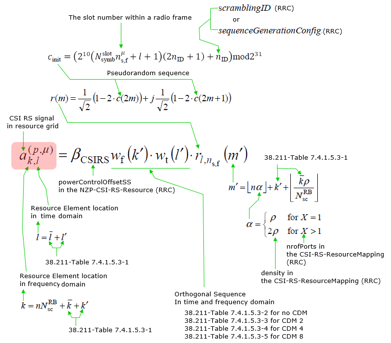
The equation looks intimidating, but the good news is that it is really answering two completely separate questions, and you can think about them one at a time :
- What values do I transmit ? – this is the sequence generation part. A pseudo random sequence is generated, modulated, and then multiplied by the CDM weights.
- Where do I put them ? – this is the resource mapping part. It decides which subcarriers and which OFDM symbols carry those values.
Most of the confusion around CSI-RS comes from mixing these two together. They are almost independent : you can change where the signal is mapped without changing a single value in the sequence, and you can change the sequence (by changing the scrambling ID) without moving a single resource element. Keep them in separate boxes in your head and the rest of this page gets much easier.
One more thing worth noticing early : the sequence is generated as a function of the slot number and symbol number, not just once at configuration time. That is why the same CSI-RS resource carries different values in different slots, and it is also why the UE has to be time synchronised before it can use CSI-RS at all – if the UE thinks it is in the wrong slot, it will generate the wrong reference sequence and the measurement becomes meaningless.
Tables for Resource Element Mapping
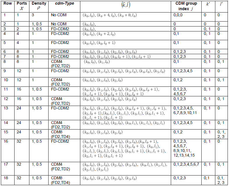
Following table contains everything about the physical resource allocation for CSI-RS. If you just take a first look, it would be almost like an encrypted document and no idea on what it mean. Follow through the explaination in this note and try to get clear undestandings on examples and you will gradually get familiar with this table.
< 38.211-Table 7.4.1.5.3-1: CSI-RS locations within a slot. >
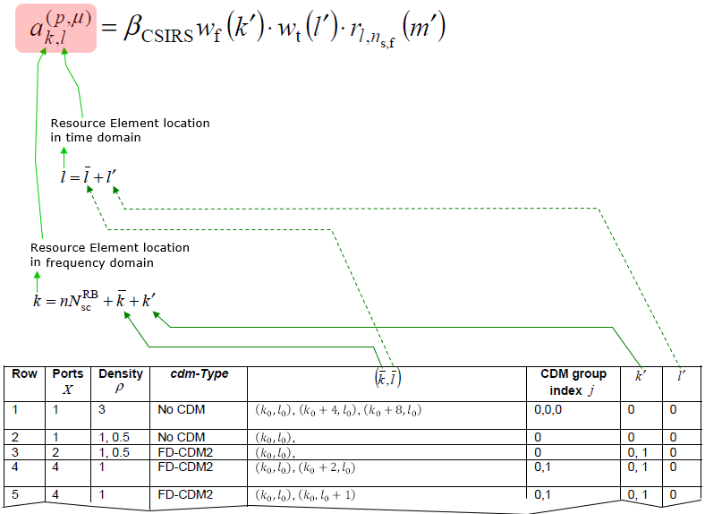
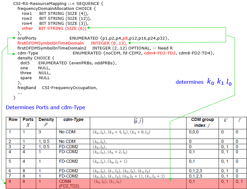
The reference location of CSI-RS in time domain is determined by RRC layer as below.
Do not try to memorize this table, and do not try to read it top to bottom. In practice you never read the whole thing – you land on exactly one row and everything you need comes from that single row. The whole table is really just a catalogue of pre-approved patterns, and the RRC configuration is how the network tells you which one it picked.
The way to use it is always the same three steps :
- Step 1 – find your row. The combination of nrofPorts, density and cdm-Type from RRC picks out one row, and only one row. This is a lookup, not a calculation.
- Step 2 – read the pattern off that row. The row tells you how many REs are used per port, and gives you the (k̄, l̄) list which is the relative position of each RE within the pattern.
- Step 3 – anchor the pattern. The row also tells you how many bits the frequency domain bitmap has (that is why the ASN.1 has row1/row2/row4/other with different sizes). The bitmap gives you the frequency anchor, and firstOFDMSymbolInTimeDomain gives you the time anchor.
So the row decides the shape of the pattern, and RRC decides where that shape is placed. If you keep that division in mind, the table becomes much less frightening – you are only ever using one line of it.
 =
=  =
= The reference location of CSI-RS in frequency domain (k1,k2,k3) is determined by RRC layer as below




- Bitmap: [b2 b1 b0] = 101 (bits 0 and 2 set).
- f(0) = 0, f(1) = 2. therefore
- ki= 4 × f(0) = 4 × 0 = 0,
- ki= 4 × f(1) = 4× 2 = 8.
f(i) is the bit number of the i th bit in the bitmap(CSI-RS-ResourceMapping.frequencyDomainAllocation) set to one, repeated across every 1/density.
Example : Row 4 (FD-CDM2, Density 1):
Ports, Density, cdm-Type are specified by following RRC parameters
- Ports = CSI-RS-ResourceMapping.nrofPorts
- cdm-Type = CSI-RS-ResourceMapping.cdm-Type
- Density = CSI-RS-ResourceMapping.density
Tables for CDM Sequence Generation
The row you picked also decides how the ports share those resource elements. When cdm-Type is anything other than noCDM, several ports sit on the same REs and are separated by an orthogonal code instead of by position. The tables below hold those codes, and there is one table per CDM type.
CDM table is used for CSI-RS signal generation as shown below.
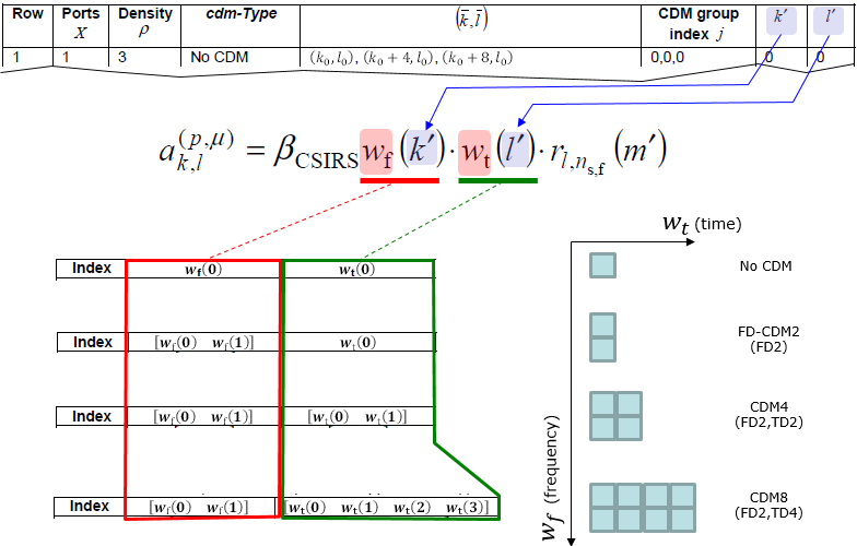
Each element values of CDM tables are specified in 38.211 as shown below.
< 38.211 - Table 7.4.1.5.3-2: The sequences wf(k) f and wt(l) for cdm-Type equal to 'no CDM'. >

< 38.211 - Table 7.4.1.5.3-3: The sequences wf(k) f and wt(l) for cdm-Type equal to fd-CDM2 >

< 38.211 - Table 7.4.1.5.3-4: The sequences wf(k) f and wt(l) for cdm-Type equal to cdm4-FD2-TD2. >
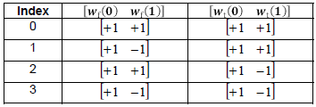
< 38.211 - Table 7.4.1.5.3-5: The sequences wf(k) f and wt(l) for cdm-Type equal to cdm8-FD2-TD4. >

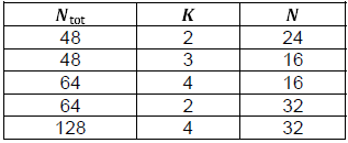
< 38.211 - Table 7.4.1.5.3-6: The supported combinations of Ntot, K and N when the number of CSI-RS ports is 48, 64, or 128. >
It is worth pausing on why CDM exists at all, because the table makes much more sense afterwards. Suppose the network has 8 antenna ports and wants the UE to measure all of them. The obvious approach is to give every port its own resource elements – but that costs 8 times the overhead, and those REs cannot carry data.
CDM (Code Division Multiplexing) is the trick that avoids paying that price. Several ports transmit on the very same resource elements, but each port multiplies its signal by a different orthogonal code. Because the codes are orthogonal, the UE can separate the ports again at the receiver. The naming tells you exactly how the code is spread :
- noCDM – no code applied. One port per RE, the simplest case.
- fd-CDM2 – a length-2 code spread over the frequency domain, i.e. over 2 adjacent subcarriers. 2 ports share the same REs.
- cdm4-FD2-TD2 – a length-4 code spread over 2 subcarriers and 2 symbols. 4 ports share the same REs.
- cdm8-FD2-TD4 – a length-8 code over 2 subcarriers and 4 symbols. 8 ports share the same REs.
This is also why the tables below are expressed as two separate weights, wf (frequency direction) and wt (time direction). The actual weight applied to a given RE is simply the product of the two.
RRC Parameter : NZP-CSI-RS-Resource
Almost all of the contents in this page is about the IE(Information Element) resourceMapping. The IE resourceMapping is a part of the NZP-CSI-RS-Resource as shown below.
Before reading the field list, it helps to know where this IE sits in the bigger picture, because CSI-RS configuration is layered and it is easy to lose track of which level you are looking at :
- NZP-CSI-RS-Resource (this IE) – describes one CSI-RS resource. Where it sits in frequency and time, how many ports, which CDM type, what scrambling ID, how often it repeats.
- NZP-CSI-RS-ResourceSet – a group of the above. This is the level where the network says 'these resources belong together', and where trs-Info lives.
- CSI-ReportConfig – says what the UE should actually measure and report using those resources, and how often.
In other words this IE answers 'what does the signal look like and where is it', while the levels above it answer 'what is it for'. A very common source of confusion is expecting a resource on its own to produce a report – it will not. A resource is only transmitted and measured because something above it refers to it.
NZP, by the way, simply means Non-Zero Power : this is a CSI-RS that actually radiates. Its counterpart, ZP-CSI-RS, uses almost the same resource description but transmits nothing at all.
Following is based on
NZP-CSI-RS-Resource ::=             SEQUENCE {
    nzp-CSI-RS-ResourceId               NZP-CSI-RS-ResourceId,
    resourceMapping                     CSI-RS-ResourceMapping,
    powerControlOffset                  INTEGER (-8..15),
    powerControlOffsetSS                ENUMERATED{db-3, db0, db3, db6}                 OPTIONAL,   -- Need R
    scramblingID                        ScramblingId,
    periodicityAndOffset                CSI-ResourcePeriodicityAndOffset                OPTIONAL,   -- Cond PeriodicOrSemiPersistent
    qcl-InfoPeriodicCSI-RS              TCI-StateId                                     OPTIONAL,   -- Cond Periodic
    ...,
    [[
    subcarrierSpacing-r18               SubcarrierSpacing                               OPTIONAL,   -- Cond LTM
    absoluteFrequencyPointA-r18         ARFCN-ValueNR                                   OPTIONAL,   -- Cond LTM
    cyclicPrefix-r18                    ENUMERATED {extended}                           OPTIONAL    -- Cond LTM
    ]],
    [[
    additionalOneSlotOffset-r19         ENUMERATED{enabled}                             OPTIONAL,   -- Need R
    additionalSlotOffset-r19            INTEGER(0..7)                                   OPTIONAL    -- Need R
    ]]
}
In short, this indicates the tci-StateId to which this CSI-RS is QCLed.
How UE figure out which CSI-RS the network is using ? (CSI-RS-ResourceMapping)
When Network allocate the CSI-RS, it selects a specific row from 38.211-Table 7.4.1.5.3-1 and fill in a set of resource elements with the specific signal. This part would be straightforward.. the challenging part is how UE can figure out which CSI-RS the gNB(Network) is using.
The answer is that Network informs UE of all the details of CSI-RS via RRC message. Let's look into what kind of RRC parameters get involved in this process.
This is worth stating plainly because it removes a lot of mystery : the UE never guesses, and the UE never searches. Unlike PSS/SSS, where the UE genuinely has to hunt blindly for a signal it has not been told about, CSI-RS is fully described in advance by RRC. By the time a CSI-RS is transmitted, the UE already knows the exact subcarriers, the exact symbols, the exact slots and the exact sequence.
So the question 'how does the UE figure it out' really becomes 'which RRC fields carry which piece of the answer'. There are only four pieces, and the next two sections walk through them :
- Which row of the table ? – from nrofPorts, cdm-Type and density.
- Where in frequency ? – from frequencyDomainAllocation (the bitmap) plus freqBand (which RBs are covered at all).
- Where in time, within the slot ? – from firstOFDMSymbolInTimeDomain.
- Which slots ? – from periodicityAndOffset, covered in the transmission timing section.
If you can answer those four questions from a real RRC message, you can draw the CSI-RS on a resource grid yourself – which is exactly what the examples later in this page do.
How to determine CSI-RS port and cdm (in Row number of 38.211 Table 7.4.1.5.3-1) ?
Row selection comes first, because every later step reads its values out of the row. Choose the wrong row and the subcarrier positions, the CDM groups and the port numbering all go wrong together. Three RRC fields decide it between them, and none of the three is enough on its own.
:This is specified by nrofPorts and cdm-Type in CSI-RS-ResourceMapping as shown below.
This is the first of the four questions, and it is the one that unlocks the table. Everything else depends on knowing which row you are on, so this is always the step to do first.
Three RRC fields work together to narrow 38.211 Table 7.4.1.5.3-1 down to a single row :
- nrofPorts – p1, p2, p4, p8 ... This eliminates most of the table immediately, since each row supports one specific port count.
- cdm-Type – noCDM, fd-CDM2, cdm4-FD2-TD2, cdm8-FD2-TD4. Several rows may share the same port count but differ in how the ports are stacked.
- density – dot5, one or three. This is 'how many REs per RB per port', and it is what separates the remaining candidates.
There is also a neat consistency check hiding here, and it is a good habit to use it : the row tells you how many (k̄, l̄) entries the pattern has, and the ASN.1 CHOICE in frequencyDomainAllocation tells you how many bits the bitmap has. Those two must agree with the row you selected. If they do not, you picked the wrong row.
Following is based on
CSI-RS-ResourceMapping ::=          SEQUENCE {
    frequencyDomainAllocation           CHOICE {
        row1                                BIT STRING (SIZE (4)),
        row2                                BIT STRING (SIZE (12)),
        row4                                BIT STRING (SIZE (3)),
        other                               BIT STRING (SIZE (6))
    },
    nrofPorts                           ENUMERATED {p1,p2,p4,p8,p12,p16,p24,p32},
    firstOFDMSymbolInTimeDomain         INTEGER (0..13),
    firstOFDMSymbolInTimeDomain2        INTEGER (2..12)                                                         OPTIONAL,   -- Need R
    cdm-Type                            ENUMERATED {noCDM, fd-CDM2, cdm4-FD2-TD2, cdm8-FD2-TD4},
    density                             CHOICE {
        dot5                                ENUMERATED {evenPRBs, oddPRBs},
        one                                 NULL,
        three                               NULL,
        spare                               NULL
    },
    freqBand                            CSI-FrequencyOccupation,
    ...
}
How to determine REs(Resource Elements) for the selected CSI-RS ?
With the row fixed, the question becomes where on the grid the signal actually lands. The row gives the pattern in relative terms, and two RRC fields give the origin that the pattern is measured from. Frequency and time are answered separately here, and it is worth keeping them apart.
: This is configured by (k_bar, l_bar) column and frequencyDomainAllocation and firstOFDMSymbolInTimeDomain of CSI-RS-ResourceMapping as shown below.
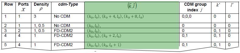
This is where the row you just selected finally turns into actual positions on the resource grid. The mechanism is simple once you see it : the table gives you a relative pattern, and RRC gives you the anchor that the pattern is placed against.
- k (subcarrier) = the frequency anchor from the frequencyDomainAllocation bitmap, plus the k̄ offsets listed in the row.
- l (symbol) = firstOFDMSymbolInTimeDomain, plus the l̄ offsets listed in the row. Some rows also use firstOFDMSymbolInTimeDomain2 for a second group of symbols.
The other thing to remember is that freqBand decides which resource blocks the pattern is repeated over. The pattern itself describes what happens inside one RB; freqBand says how far across the carrier that repetition extends.
Following is based on
CSI-RS-ResourceMapping ::=          SEQUENCE {
    frequencyDomainAllocation           CHOICE {
        row1                                BIT STRING (SIZE (4)),
        row2                                BIT STRING (SIZE (12)),
        row4                                BIT STRING (SIZE (3)),
        other                               BIT STRING (SIZE (6))
    },
    nrofPorts                           ENUMERATED {p1,p2,p4,p8,p12,p16,p24,p32},
    firstOFDMSymbolInTimeDomain         INTEGER (0..13),
    firstOFDMSymbolInTimeDomain2        INTEGER (2..12)                                                         OPTIONAL,   -- Need R
    cdm-Type                            ENUMERATED {noCDM, fd-CDM2, cdm4-FD2-TD2, cdm8-FD2-TD4},
    density                             CHOICE {
        dot5                                ENUMERATED {evenPRBs, oddPRBs},
        one                                 NULL,
        three                               NULL,
        spare                               NULL
    },
    freqBand                            CSI-FrequencyOccupation,
    ...
}

CSI-FrequencyOccupation ::=         SEQUENCE {
    startingRB                          INTEGER (0..maxNrofPhysicalResourceBlocks-1),
    nrofRBs                             INTEGER (24..maxNrofPhysicalResourceBlocksPlus1),
    ...
}
Combining thse two, we come come up with an example as shown below.
: This is another complicated story and is explained in a separate page here.
CSI RS Resource Mapping Examples
Eight worked configurations follow, ordered so that each one adds a single new difficulty. The first three change nothing but the frequency bitmap. The next two introduce density one and then CDM. The last three move to eight ports, where the CDM group index and the port numbering finally start to matter.
This section is to show various examples of configuring following RRC Parameters.
This is the part of the page that makes everything above click, so if the tables felt abstract, this is where to slow down. Each example takes a real RRC configuration and resolves it all the way to a picture of the resource grid, using exactly the steps described above.
The examples are ordered deliberately, from simple to complex, and they are much easier if you read them in order :
- Examples 01 to 03 – single port (p1), density three, no CDM. The simplest possible case. Only the bitmap changes between them, so these three show you very clearly what the frequency domain bitmap actually does.
- Examples 04 and 05 – still small, but now with 2 and 3 ports, and example 05 introduces CDM. This is where you see multiple ports sharing REs for the first time.
- Examples 06 to 08 – 8 ports. Examples 06 and 07 differ only in the bitmap, and example 08 keeps the same bitmap as 07 but switches the CDM type. Comparing 07 and 08 side by side is the clearest way to see what CDM changes and what it does not.
A suggestion that is worth the effort : try to draw one example yourself before looking at the answer. Pick example 01, work out the row, the k and l values, and sketch the grid. Checking your sketch against the figure is far more effective than reading all eight examples passively.
Following is based on
CSI-RS-ResourceMapping ::=          SEQUENCE {
    frequencyDomainAllocation           CHOICE {
        row1                                BIT STRING (SIZE (4)),
        row2                                BIT STRING (SIZE (12)),
        row4                                BIT STRING (SIZE (3)),
        other                               BIT STRING (SIZE (6))
    },
    nrofPorts                           ENUMERATED {p1,p2,p4,p8,p12,p16,p24,p32},
    firstOFDMSymbolInTimeDomain         INTEGER (0..13),
    firstOFDMSymbolInTimeDomain2        INTEGER (2..12)                                                         OPTIONAL,   -- Need R
    cdm-Type                            ENUMERATED {noCDM, fd-CDM2, cdm4-FD2-TD2, cdm8-FD2-TD4},
    density                             CHOICE {
        dot5                                ENUMERATED {evenPRBs, oddPRBs},
        one                                 NULL,
        three                               NULL,
        spare                               NULL
    },
    freqBand                            CSI-FrequencyOccupation,
    ...
}
Followings are some of the examples showing the location (Resource Elements) within a PRB(physical resource block). Since these examples are showing the location only within one RB, n N^RB_sc term is removed in the equation determining k value.
Example 01 >
The simplest case on the list, and the one to read slowly. One port, no CDM and density three put us on row 1 of 38.211 Table 7.4.1.5.3-1. That row places three resource elements per resource block, at k0, k0 + 4 and k0 + 8. The only thing the bitmap has to settle is where k0 sits.
Given the following RRC parameters,
density = three
nrofPorts = p1
cdm-Type = noCDM
frequencyDomainAllocation.row1 = 0001
firstOFDMSymbolinTimeDomain = 4
According to 38.211-Table 7.4.1.5.3-1,


From the given configuration:
- k prime (k'): {0} => k'[0] = 0
- l prime (l'): {0} => l'[0] = 0
According to the RRC parameters:
- k0: 0 (based on frequencyDomainAllocation.row1 = 0001)
- l0: 4 (based on firstOFDMSymbolInTimeDomain = 4)
Using this information and 38.211-Table 7.4.1.5.3-1, the final resource elements for CSI-RS placement are:
- (k, l) = (k0 + k'[0], l0 + l'[0])
- (k, l) = (k0 + 4 + k'[0], l0 + l'[0])
- (k, l) = (k0 + 8 + k'[0], l0 + l'[0])
By substitution:
- (k, l) = (0 + 0 + 0, 4 + 0) = (0, 4)
- (k, l) = (0 + 4 + 0, 4 + 0) = (4, 4)
- (k, l) = (0 + 8 + 0, 4 + 0) = (8, 4)
Final positions of CSI-RS resource elements are:
- (4, 4)
- (4, 4)
- (8, 4)
|
|
0 |
1 |
2 |
3 |
4 |
5 |
6 |
7 |
8 |
9 |
10 |
11 |
12 |
13 |
|
11 |
|
|
|
|
|
|
|
|
|
|
|
|
|
|
|
10 |
|
|
|
|
|
|
|
|
|
|
|
|
|
|
|
9 |
|
|
|
|
|
|
|
|
|
|
|
|
|
|
|
8 |
|
|
|
|
|
|
|
|
|
|
|
|
|
|
|
7 |
|
|
|
|
|
|
|
|
|
|
|
|
|
|
|
6 |
|
|
|
|
|
|
|
|
|
|
|
|
|
|
|
5 |
|
|
|
|
|
|
|
|
|
|
|
|
|
|
|
4 |
|
|
|
|
|
|
|
|
|
|
|
|
|
|
|
3 |
|
|
|
|
|
|
|
|
|
|
|
|
|
|
|
2 |
|
|
|
|
|
|
|
|
|
|
|
|
|
|
|
1 |
|
|
|
|
|
|
|
|
|
|
|
|
|
|
|
0 |
|
|
|
|
|
|
|
|
|
|
|
|
|
|
Example 02 >
Nothing changes here except one bit in the bitmap. Example 01 fixes the row, the port count, the CDM type and the symbol, and none of them moves here. So this is a clean test of whether you can read frequencyDomainAllocation on its own. Compare the k0 you get with the one Example 01 produced.
Given the following RRC parameters,
density = three
nrofPorts = p1
cdm-Type = noCDM
frequencyDomainAllocation.row1 = 0100
firstOFDMSymbolinTimeDomain = 4
According to 38.211-Table 7.4.1.5.3-1,
-
Density: three
- Indicates 3 Resource Elements (REs) per Physical Resource Block (PRB).
-
Number of Ports: p1
- Single antenna port (Port 0) is configured.
-
CDM Type: noCDM
- No Code Division Multiplexing (CDM) is applied.
-
Frequency Domain Allocation: row1 = 0100
- A 4-bit bitmap is used for Row 1 configurations:
- Bits: [b3, b2, b1, b0] = [0, 1, 0, 0].
- The second bit (b2) is set to "1", which corresponds to the subcarrier offset k0 = 2.
-
First OFDM Symbul in Time Domain: 4
- The starting OFDM symbul index in the time domain is l0 = 4.
- CSI-RS locations in the frequency and time domains are described as:
- (k0, l0)
- (k0 + 4, l0)
- (k0 + 8, l0)
- CDM group index (j): 0, 0, 0
- k′: 0 (frequency offset within the resource block)
- l′: 0 (time offset within the OFDM symbul)
-
From the bitmap [b3, b2, b1, b0] = [0, 1, 0, 0]:
- The bit b2 = 1, so k0 = 2.
-
Using the firstOFDMSymbulInTimeDomain parameter:
- l0 = 4.
-
Using the formulas from Table 7.4.1.5.3-1, the resource element positions are determined as:
- (k, l) = (k0 + k′[0], l0 + l′[0])
- (k, l) = (k0 + 4 + k′[0], l0 + l′[0])
- (k, l) = (k0 + 8 + k′[0], l0 + l′[0])
-
For the first RE:
- (k, l) = (2 + 0, 4 + 0) = (2, 4)
-
For the second RE:
- (k, l) = (2 + 4, 4 + 0) = (6, 4)
-
For the third RE:
- (k, l) = (2 + 8, 4 + 0) = (10, 4)
- (2, 4)
- (6, 4)
- (10, 4)
- Subcarrier indices k = 2, 6, 10
- In the time domain symbul l = 4.
Given RRC Parameters:
Referencing 3GPP Table 7.4.1.5.3-1:
From 3GPP TS 38.211, Table 7.4.1.5.3-1, the configuration for Row 1 with 1 port (density: three) and noCDM is:
Step-by-Step Derivation:
Substituting Values:
Final Resource Element (RE) Positions:
The final CSI-RS RE positions in the grid are:
This means the CSI-RS signals will be transmitted at:
|
|
0 |
1 |
2 |
3 |
4 |
5 |
6 |
7 |
8 |
9 |
10 |
11 |
12 |
13 |
|
11 |
|
|
|
|
|
|
|
|
|
|
|
|
|
|
|
10 |
|
|
|
|
|
|
|
|
|
|
|
|
|
|
|
9 |
|
|
|
|
|
|
|
|
|
|
|
|
|
|
|
8 |
|
|
|
|
|
|
|
|
|
|
|
|
|
|
|
7 |
|
|
|
|
|
|
|
|
|
|
|
|
|
|
|
6 |
|
|
|
|
|
|
|
|
|
|
|
|
|
|
|
5 |
|
|
|
|
|
|
|
|
|
|
|
|
|
|
|
4 |
|
|
|
|
|
|
|
|
|
|
|
|
|
|
|
3 |
|
|
|
|
|
|
|
|
|
|
|
|
|
|
|
2 |
|
|
|
|
|
|
|
|
|
|
|
|
|
|
|
1 |
|
|
|
|
|
|
|
|
|
|
|
|
|
|
|
0 |
|
|
|
|
|
|
|
|
|
|
|
|
|
|
Example 03 >
The third bitmap value completes the set, and this one is taken from a real configuration rather than invented. A single port at density three is the TRS pattern, so this example doubles as a look at what a tracking reference signal occupies. The row and the symbol are unchanged again.
Given the following RRC parameters, (this example is based on TRS case in 38.508-1 Table 4.6.3-45: CSI-RS-ResourceMapping)
density = three
nrofPorts = p1
cdm-Type = noCDM
frequencyDomainAllocation.row1 = 1000 // From density,nrofPorts we can guess that this is for row1.
firstOFDMSymbolinTimeDomain = 4
According to 38.211-Table 7.4.1.5.3-1,
-
Density: three
- Indicates 3 Resource Elements (REs) per Physical Resource Block (PRB).
-
Number of Ports: p1
- Single antenna port (Port 0) is configured.
-
CDM Type: noCDM
- No Code Division Multiplexing (CDM) is applied.
-
Frequency Domain Allocation: row1 = 1000
- A 4-bit bitmap is used for Row 1 configurations:
- Bits: [b3, b2, b1, b0] = [1, 0, 0, 0].
- The first bit (b3) is set to "1", which corresponds to the subcarrier offset k0 = 3.
-
First OFDM Symbul in Time Domain: 4
- The starting OFDM symbul index in the time domain is l0 = 4.
- CSI-RS locations in the frequency and time domains are described as:
- (k0, l0)
- (k0 + 4, l0)
- (k0 + 8, l0)
- CDM group index (j): 0, 0, 0
- k′: 0 (frequency offset within the resource block)
- l′: 0 (time offset within the OFDM symbul)
-
From the bitmap [b3, b2, b1, b0] = [1, 0, 0, 0]:
- The bit b3 = 1, so k0 = 3.
-
Using the firstOFDMSymbulInTimeDomain parameter:
- l0 = 4.
-
Using the formulas from Table 7.4.1.5.3-1, the CSI-RS resource element positions are calculated as:
- (k, l) = (k0 + k′[0], l0 + l′[0])
- (k, l) = (k0 + 4 + k′[0], l0 + l′[0])
- (k, l) = (k0 + 8 + k′[0], l0 + l′[0])
-
For the first RE:
- (k, l) = (3 + 0, 4 + 0) = (3, 4)
-
For the second RE:
- (k, l) = (3 + 4, 4 + 0) = (7, 4)
-
For the third RE:
- (k, l) = (3 + 8, 4 + 0) = (11, 4)
- (3, 4)
- (7, 4)
- (11, 4)
- Subcarrier indices k = 3, 7, 11
- In the time domain symbul l = 4.
Given RRC Parameters:
Referencing 3GPP Table 7.4.1.5.3-1:
From 3GPP TS 38.211, Table 7.4.1.5.3-1, the configuration for Row 1 with 1 port (density: three) and noCDM is:
Step-by-Step Derivation:
Substituting Values:
Final Resource Element (RE) Positions:
The final CSI-RS RE positions in the grid are:
This means the CSI-RS signals will be transmitted at:
|
|
0 |
1 |
2 |
3 |
4 |
5 |
6 |
7 |
8 |
9 |
10 |
11 |
12 |
13 |
|
11 |
|
|
|
|
|
|
|
|
|
|
|
|
|
|
|
10 |
|
|
|
|
|
|
|
|
|
|
|
|
|
|
|
9 |
|
|
|
|
|
|
|
|
|
|
|
|
|
|
|
8 |
|
|
|
|
|
|
|
|
|
|
|
|
|
|
|
7 |
|
|
|
|
|
|
|
|
|
|
|
|
|
|
|
6 |
|
|
|
|
|
|
|
|
|
|
|
|
|
|
|
5 |
|
|
|
|
|
|
|
|
|
|
|
|
|
|
|
4 |
|
|
|
|
|
|
|
|
|
|
|
|
|
|
|
3 |
|
|
|
|
|
|
|
|
|
|
|
|
|
|
|
2 |
|
|
|
|
|
|
|
|
|
|
|
|
|
|
|
1 |
|
|
|
|
|
|
|
|
|
|
|
|
|
|
|
0 |
|
|
|
|
|
|
|
|
|
|
|
|
|
|
Example 04 >
Density drops from three to one here, and that changes the row. One port at density one is row 2, which places a single resource element per resource block instead of three. The bitmap is twelve bits wide rather than four, because one RE per block leaves twelve positions to choose between.
Given the following RRC parameters,
density = one
nrofPorts = p1
cdm-Type = noCDM
frequencyDomainAllocation.row2 = 010000000000
firstOFDMSymbolinTimeDomain = 13
According to 38.211-Table 7.4.1.5.3-1,

-
Density: one
- Indicates that CSI-RS occupies every subcarrier in the configured frequency domain.
-
Number of Ports: p1
- Single antenna port (Port 0) is configured.
-
CDM Type: noCDM
- No Code Division Multiplexing (CDM) is applied.
-
Frequency Domain Allocation: row2 = 010000000000
- A 12-bit bitmap is used for Row 2 configurations:
- Bits: [b11, b10, ..., b0] = [0, 1, 0, 0, 0, 0, 0, 0, 0, 0, 0, 0].
- The bit b10 is set to "1", which corresponds to the subcarrier offset k0 = 10.
-
First OFDM Symbul in Time Domain: 13
- The starting OFDM symbul index in the time domain is l0 = 13.
- CSI-RS location in the frequency and time domain is described as:
- (k0, l0)
- CDM group index (j): 0
- k′: 0 (frequency offset within the resource block)
- l′: 0 (time offset within the OFDM symbul)
-
From the bitmap [b11, b10, ..., b0] = [0, 1, 0, 0, 0, 0, 0, 0, 0, 0, 0, 0]:
- The bit b10 = 1, so k0 = 10.
-
Using the firstOFDMSymbulInTimeDomain parameter:
- l0 = 13.
-
Using the formula from Table 7.4.1.5.3-1, the CSI-RS resource element position is calculated as:
- (k, l) = (k0 + k′[0], l0 + l′[0]).
- (10, 13)
- Subcarrier index k = 10
- In the time domain symbul l = 13.
Given RRC Parameters:
Referencing 3GPP Table 7.4.1.5.3-1:
From 3GPP TS 38.211, Table 7.4.1.5.3-1, the configuration for Row 2 with 1 port (density: one) and noCDM is:
Step-by-Step Derivation:
Substituting Values:
(k, l) = (10 + 0, 13 + 0) = (10, 13)
Final Resource Element (RE) Position:
The final CSI-RS RE position in the grid is:
This means the CSI-RS signal will be transmitted at:
|
|
0 |
1 |
2 |
3 |
4 |
5 |
6 |
7 |
8 |
9 |
10 |
11 |
12 |
13 |
|
11 |
|
|
|
|
|
|
|
|
|
|
|
|
|
|
|
10 |
|
|
|
|
|
|
|
|
|
|
|
|
|
|
|
9 |
|
|
|
|
|
|
|
|
|
|
|
|
|
|
|
8 |
|
|
|
|
|
|
|
|
|
|
|
|
|
|
|
7 |
|
|
|
|
|
|
|
|
|
|
|
|
|
|
|
6 |
|
|
|
|
|
|
|
|
|
|
|
|
|
|
|
5 |
|
|
|
|
|
|
|
|
|
|
|
|
|
|
|
4 |
|
|
|
|
|
|
|
|
|
|
|
|
|
|
|
3 |
|
|
|
|
|
|
|
|
|
|
|
|
|
|
|
2 |
|
|
|
|
|
|
|
|
|
|
|
|
|
|
|
1 |
|
|
|
|
|
|
|
|
|
|
|
|
|
|
|
0 |
|
|
|
|
|
|
|
|
|
|
|
|
|
|
Example 05 >
CDM appears for the first time in this example. Two ports share one pair of resource elements and are separated by the FD-CDM2 code rather than by position, which puts us on row 3. Note also that the row number is given here rather than derived. Outside rows 1, 2 and 4 the bitmap alone cannot tell you which row applies.
Given the following RRC parameters,
density = one
nrofPorts = p2
cdm-Type = FD-CDM2
frequencyDomainAllocation.other = 001000
firstOFDMSymbolinTimeDomain = 13
Assume that row = 3 (you need additional information to determine the row number other than 1,2,4. In this example, it is given)
According to 38.211-Table 7.4.1.5.3-1,

-
Density: one
- Indicates that CSI-RS occupies every subcarrier in the configured frequency domain.
-
Number of Ports: p2
- Two antenna ports (Port 0 and Port 1) are configured.
-
CDM Type: FD-CDM2
- Frequency domain code division multiplexing with two orthogonal sequences is applied.
-
Frequency Domain Allocation: other = 001000
- A 6-bit bitmap is used for Row 3 configurations:
- Bits: [b5, b4, ..., b0] = [0, 0, 1, 0, 0, 0].
- The bit b2 is set to "1", which corresponds to the subcarrier offset k0 = 6 (calculated as 2 × bit position).
-
First OFDM Symbul in Time Domain: 13
- The starting OFDM symbul index in the time domain is l0 = 13.
- CSI-RS locations in the frequency and time domains are described as:
- (k0, l0)
- CDM group index (j): 0
- k′: [0, 1]
- l′: 0
-
From the bitmap [b5, b4, ..., b0] = [0, 0, 1, 0, 0, 0]:
- The bit b2 = 1, so k0 = 6.
-
Using the firstOFDMSymbulInTimeDomain parameter:
- l0 = 13.
-
Using the formula from Table 7.4.1.5.3-1, the CSI-RS resource element positions are calculated as:
- (k, l) = (k0 + k′[0], l0 + l′[0]).
- (k, l) = (k0 + k′[1], l0 + l′[0]).
- (k, l) = (6 + 0, 13 + 0) = (6, 13)
- (k, l) = (6 + 1, 13 + 0) = (7, 13)
- (6, 13)
- (7, 13)
- Subcarrier indices k = 6 and k = 7
- In the time domain symbul l = 13.
Given RRC Parameters:
Referencing 3GPP Table 7.4.1.5.3-1:
From 3GPP TS 38.211, Table 7.4.1.5.3-1, the configuration for Row 3 with 2 ports (density: one) and FD-CDM2 is:
Step-by-Step Derivation:
Substituting Values:
Final Resource Element (RE) Positions:
The final CSI-RS RE positions in the grid are:
This means the CSI-RS signals will be transmitted at:
|
|
0 |
1 |
2 |
3 |
4 |
5 |
6 |
7 |
8 |
9 |
10 |
11 |
12 |
13 |
|
11 |
|
|
|
|
|
|
|
|
|
|
|
|
|
|
|
10 |
|
|
|
|
|
|
|
|
|
|
|
|
|
|
|
9 |
|
|
|
|
|
|
|
|
|
|
|
|
|
|
|
8 |
|
|
|
|
|
|
|
|
|
|
|
|
|
|
|
7 |
|
|
|
|
|
|
|
|
|
|
|
|
|
wf(1) |
|
6 |
|
|
|
|
|
|
|
|
|
|
|
|
|
wf(0) |
|
5 |
|
|
|
|
|
|
|
|
|
|
|
|
|
|
|
4 |
|
|
|
|
|
|
|
|
|
|
|
|
|
|
|
3 |
|
|
|
|
|
|
|
|
|
|
|
|
|
|
|
2 |
|
|
|
|
|
|
|
|
|
|
|
|
|
|
|
1 |
|
|
|
|
|
|
|
|
|
|
|
|
|
|
|
0 |
|
|
|
|
|
|
|
|
|
|
|
|
|
|
Example 06 >
Eight ports arrive here, and with them the CDM group index. Row 6 spreads four CDM groups across four subcarrier positions in the same symbol, and each group carries two ports under an FD-CDM2 code. That is where the port numbering formula in this example comes from.
Given the following RRC parameters, (this example is based on FR1 case in 38.508-1 Table 4.6.3-45: CSI-RS-ResourceMapping)
density = one
nrofPorts = p8
cdm-Type = fd-CDM2
frequencyDomainAllocation.other = 011110 //From density,nrofPorts,cdm-Tye it is assumed that this is for row6.
firstOFDMSymbolinTimeDomain = 3
According to 38.211-Table 7.4.1.5.3-1,

-
Density: one
- Indicates that CSI-RS occupies every subcarrier in the configured frequency domain.
-
Number of Ports: p8
- Eight antenna ports (Ports 0 to 7) are configured.
-
CDM Type: FD-CDM2
- Frequency domain code division multiplexing with two orthogonal sequences is applied.
-
Frequency Domain Allocation: other = 011110
- A 6-bit bitmap is used for Row 6 configurations:
- Bits: [b5, b4, ..., b0] = [0, 1, 1, 1, 1, 0].
- The bits b1, b2, b3, b4 are set to "1," which correspond to subcarrier offsets:
- k0 = 2
- k1 = 4
- k2 = 6
- k3 = 8
-
First OFDM Symbul in Time Domain: 3
- The starting OFDM symbul index in the time domain is l0 = 3.
- CSI-RS locations in the frequency and time domains are described as:
- (k0, l0), (k1, l0), (k2, l0), (k3, l0)
- CDM group index (j): 0, 1, 2, 3
- k′: [0, 1]
- l′: 0
-
From the bitmap [b5, b4, ..., b0] = [0, 1, 1, 1, 1, 0]:
- The bits b1, b2, b3, b4 = 1 correspond to:
- k0 = 2
- k1 = 4
- k2 = 6
- k3 = 8
-
Using the firstOFDMSymbulInTimeDomain parameter:
- l0 = 3.
-
Using the formula from Table 7.4.1.5.3-1, the CSI-RS resource element positions for each port and frequency offset are calculated as:
- For k′:0: (k, l) = (ki + k′[0], l0 + l′[0]).
- For k′:1: (k, l) = (ki + k′[1], l0 + l′[0]).
- k′:0 (2, 3), (4, 3), (6, 3), (8, 3)
- k′:1 (3, 3), (5, 3), (7, 3), (9, 3)
- Subcarrier indices k = 2, 3, 4, 5, 6, 7, 8, 9
- In the time domain symbol l = 3.
Given RRC Parameters:
Referencing 3GPP Table 7.4.1.5.3-1:
From 3GPP TS 38.211, Table 7.4.1.5.3-1, the configuration for Row 6 with 8 ports (density: one) and FD-CDM2 is:
Step-by-Step Derivation:
Final Resource Element (RE) Positions:
The final CSI-RS RE positions in the grid are:
This means the CSI-RS signals will be transmitted at:
|
|
0 |
1 |
2 |
3 |
4 |
5 |
6 |
7 |
8 |
9 |
10 |
11 |
12 |
13 |
|
11 |
|
|
|
|
|
|
|
|
|
|
|
|
|
|
|
10 |
|
|
|
|
|
|
|
|
|
|
|
|
|
|
|
9 |
|
|
|
wf(1) |
|
|
|
|
|
|
|
|
|
|
|
8 |
|
|
|
wf(0) |
|
|
|
|
|
|
|
|
|
|
|
7 |
|
|
|
wf(1) |
|
|
|
|
|
|
|
|
|
|
|
6 |
|
|
|
wf(0) |
|
|
|
|
|
|
|
|
|
|
|
5 |
|
|
|
wf(1) |
|
|
|
|
|
|
|
|
|
|
|
4 |
|
|
|
wf(0) |
|
|
|
|
|
|
|
|
|
|
|
3 |
|
|
|
wf(1) |
|
|
|
|
|
|
|
|
|
|
|
2 |
|
|
|
wf(0) |
|
|
|
|
|
|
|
|
|
|
|
1 |
|
|
|
|
|
|
|
|
|
|
|
|
|
|
|
0 |
|
|
|
|
|
|
|
|
|
|
|
|
|
|
Since this example is using FD-CDM2, it is assumed that 's' is determined by the index value of the following table and 'L' becomes 2. N is given in this example (38.211-Table 7.4.1.5.3-1) is 8.
< 38.211 - Table 7.4.1.5.3-3: The sequences wf(k) f and wt(l) for cdm-Type equal to 'FD-CDM2'. >
Based on this information, j and s can be calculated as follows.
s = 0,1 (index of Table 7.4.1.5.3-3)
j = 0,1,...,N/L-1 = 0,1,...,(8/2-1) = 0,1,2,3
Now we can calculate the antenna port as follows.
p = 3000 + s + j L , where s = {0,1}, j = {0,1,2,3}
= 3000 + {0,1} + {0,1,2,3} 2
= {3000, 3002, 3004, 3006, 3001, 3003, 3005, 3007}
Example 07 >
Same eight ports and the same CDM type as Example 06, but a different row, and the difference is worth seeing. Row 7 uses two subcarrier positions across two symbols rather than four positions in one symbol. So the pattern now occupies l0 and l0 + 1.
Given the following RRC parameters, (this example is based on FR1 case in 38.508-1 Table 4.6.3-45: CSI-RS-ResourceMapping)
density = one
nrofPorts = p8
cdm-Type = fd-CDM2
frequencyDomainAllocation.other = 000110 //From density,nrofPorts,cdm-Tye it is assumed that this is for row7.
firstOFDMSymbolinTimeDomain = 3
According to 38.211-Table 7.4.1.5.3-1,

-
Density: one
- Indicates that CSI-RS occupies every subcarrier in the configured frequency domain.
-
Number of Ports: p8
- Eight antenna ports (Ports 0 to 7) are configured.
-
CDM Type: FD-CDM2
- Frequency domain code division multiplexing with two orthogonal sequences is applied.
-
Frequency Domain Allocation: other = 000110
- A 6-bit bitmap is used for Row 7 configurations:
- Bits: [b5, b4, ..., b0] = [0, 0, 0, 1, 1, 0].
- The bits b2, b3 are set to "1," which correspond to subcarrier offsets:
- k0 = 2 (based on frequencyDomainAllocation.other = 000110)
- k1 = 4 (based on frequencyDomainAllocation.other = 000110)
-
First OFDM Symbul in Time Domain: 3
- The starting OFDM symbul index in the time domain is l0 = 3. (based on firstOFDMSymbolinTimeDomain = 3)
- For k' = 0:
- (ki + k'[0], l0)
- (ki + k'[0], l0 + 1)
- For k' = 1:
- (ki + k'[1], l0)
- (ki + k'[1], l0 + 1)
- For k' = 0:
- At l0 = 3:
- (k0 + k'[0], l0) = (2 + 0, 3) = (2, 3)
- (k1 + k'[0], l0) = (4 + 0, 3) = (4, 3)
- At l0 + 1 = 4:
- (k0 + k'[0], l0 + 1) = (2 + 0, 4) = (2, 4)
- (k1 + k'[0], l0 + 1) = (4 + 0, 4) = (4, 4)
- At l0 = 3:
- For k' = 1:
- At l0 = 3:
- (k0 + k'[1], l0) = (2 + 1, 3) = (3, 3)
- (k1 + k'[1], l0) = (4 + 1, 3) = (5, 3)
- At l0 + 1 = 4:
- (k0 + k'[1], l0 + 1) = (2 + 1, 4) = (3, 4)
- (k1 + k'[1], l0 + 1) = (4 + 1, 4) = (5, 4)
- At l0 = 3:
- For k' = 0:
- (2, 3), (2, 4) for k0 = 2
- (4, 3), (4, 4) for k1 = 4
- For k' = 1:
- (3, 3), (3, 4) for k0 = 2
- (5, 3), (5, 4) for k1 = 4
Given RRC Parameters:
Calculations Based on k' = [0, 1]:
From 3GPP TS 38.211, Table 7.4.1.5.3-1, the CSI-RS positions are grouped by k' = [0, 1] for each subcarrier position (k0, k1) and time domain symbul (l0, l0 + 1).
General Formula:
Substituting Values:
Final Grouped Positions (By k'):
|
|
0 |
1 |
2 |
3 |
4 |
5 |
6 |
7 |
8 |
9 |
10 |
11 |
12 |
13 |
|
11 |
|
|
|
|
|
|
|
|
|
|
|
|
|
|
|
10 |
|
|
|
|
|
|
|
|
|
|
|
|
|
|
|
9 |
|
|
|
|
|
|
|
|
|
|
|
|
|
|
|
8 |
|
|
|
|
|
|
|
|
|
|
|
|
|
|
|
7 |
|
|
|
|
|
|
|
|
|
|
|
|
|
|
|
6 |
|
|
|
|
|
|
|
|
|
|
|
|
|
|
|
5 |
|
|
|
wf(1) |
wf(1) |
|
|
|
|
|
|
|
|
|
|
4 |
|
|
|
wf(0) |
wf(0) |
|
|
|
|
|
|
|
|
|
|
3 |
|
|
|
wf(1) |
wf(1) |
|
|
|
|
|
|
|
|
|
|
2 |
|
|
|
wf(0) |
wf(0) |
|
|
|
|
|
|
|
|
|
|
1 |
|
|
|
|
|
|
|
|
|
|
|
|
|
|
|
0 |
|
|
|
|
|
|
|
|
|
|
|
|
|
|
Since this example is using FD-CDM2, it is assumed that 's' is determined by the index value of the following table and 'L' becomes 2. N is given in this example (38.211-Table 7.4.1.5.3-1) is 8.
< 38.211 - Table 7.4.1.5.3-3: The sequences wf(k) f and wt(l) for cdm-Type equal to 'FD-CDM2'. >
Based on this information, j and s can be calculated as follows.
s = 0,1 (index of Table 7.4.1.5.3-3)
j = 0,1,...,N/L-1 = 0,1,...,(8/2-1) = 0,1,2,3
Now we can calculate the antenna port as follows.
p = 3000 + s + j L , where s = {0,1}, j = {0,1,2,3}
= 3000 + {0,1} + {0,1,2,3} 2
= {3000, 3002, 3004, 3006, 3001, 3003, 3005, 3007}
Example 08 >
This last example keeps the bitmap of Example 07 and changes only the CDM type. CDM4 combines two frequency codes with two time codes, so four ports share one block of resource elements instead of two. The weights come from 38.211 Table 7.4.1.5.3-4, which is why this example needs an l prime as well as a k prime.
Given the following RRC parameters, (this example is based on FR1 case in 38.508-1 Table 4.6.3-45: CSI-RS-ResourceMapping)
density = one
nrofPorts = p8
cdm-Type = CDM4(FD2,TD2)
frequencyDomainAllocation.other = 000110 //From density,nrofPorts,cdm-Tye it is assumed that this is for row8.
firstOFDMSymbolinTimeDomain = 3
According to 38.211-Table 7.4.1.5.3-1,

-
Density: one
- Indicates that CSI-RS occupies every subcarrier in the configured frequency domain.
-
Number of Ports: p8
- Eight antenna ports (Ports 0 to 7) are configured.
-
CDM Type: CDM4(FD2,TD2)
- Code division multiplexing with four orthogonal codes is applied:
- FD2: Two orthogonal sequences in the frequency domain.
- TD2: Two orthogonal sequences in the time domain.
-
Frequency Domain Allocation: other = 000110
- A 6-bit bitmap is used for Row 8 configurations:
- Bits: [b5, b4, ..., b0] = [0, 0, 0, 1, 1, 0].
- The bits b2, b3 are set to "1," which correspond to subcarrier offsets:
- k0 = 2 (based on frequencyDomainAllocation.other = 000110)
- k1 = 4 (based on frequencyDomainAllocation.other = 000110)
-
First OFDM Symbul in Time Domain: 3
- The starting OFDM symbul index in the time domain is l0 = 3 (based on firstOFDMSymbolinTimeDomain = 3).
- For k' = 0:
- (ki + k'[0], l0 + l'[0])
- (ki + k'[0], l0 + l'[1])
- For k' = 1:
- (ki + k'[1], l0 + l'[0])
- (ki + k'[1], l0 + l'[1])
- For k' = 0:
- At l'[0] = 0 (l0 = 3):
- (k0 + k'[0], l0 + l'[0]) = (2 + 0, 3 + 0) = (2, 3)
- (k1 + k'[0], l0 + l'[0]) = (4 + 0, 3 + 0) = (4, 3)
- At l'[1] = 1 (l0 + 1 = 4):
- (k0 + k'[0], l0 + l'[1]) = (2 + 0, 3 + 1) = (2, 4)
- (k1 + k'[0], l0 + l'[1]) = (4 + 0, 3 + 1) = (4, 4)
- At l'[0] = 0 (l0 = 3):
- For k' = 1:
- At l'[0] = 0 (l0 = 3):
- (k0 + k'[1], l0 + l'[0]) = (2 + 1, 3 + 0) = (3, 3)
- (k1 + k'[1], l0 + l'[0]) = (4 + 1, 3 + 0) = (5, 3)
- At l'[1] = 1 (l0 + 1 = 4):
- (k0 + k'[1], l0 + l'[1]) = (2 + 1, 3 + 1) = (3, 4)
- (k1 + k'[1], l0 + l'[1]) = (4 + 1, 3 + 1) = (5, 4)
- At l'[0] = 0 (l0 = 3):
- For k' = 0:
- (2, 3), (2, 4) for k0 = 2
- (4, 3), (4, 4) for k1 = 4
- For k' = 1:
- (3, 3), (3, 4) for k0 = 2
- (5, 3), (5, 4) for k1 = 4
Given RRC Parameters:
Calculations Based on k' = [0, 1] and l' = [0, 1]:
From 3GPP TS 38.211, Table 7.4.1.5.3-1, the CSI-RS positions are grouped by k' = [0, 1] and l' = [0, 1] for each subcarrier position (k0, k1) and time symbul (l0, l0 + 1).
General Formula:
Substituting Values:
Final Grouped Positions (By k'):
|
|
0 |
1 |
2 |
3 |
4 |
5 |
6 |
7 |
8 |
9 |
10 |
11 |
12 |
13 |
|
11 |
|
|
|
|
|
|
|
|
|
|
|
|
|
|
|
10 |
|
|
|
|
|
|
|
|
|
|
|
|
|
|
|
9 |
|
|
|
|
|
|
|
|
|
|
|
|
|
|
|
8 |
|
|
|
|
|
|
|
|
|
|
|
|
|
|
|
7 |
|
|
|
|
|
|
|
|
|
|
|
|
|
|
|
6 |
|
|
|
|
|
|
|
|
|
|
|
|
|
|
|
5 |
|
|
|
wft1 |
wft1 |
|
|
|
|
|
|
|
|
|
|
4 |
|
|
|
wft0 |
wft0 |
|
|
|
|
|
|
|
|
|
|
3 |
|
|
|
wft1 |
wft1 |
|
|
|
|
|
|
|
|
|
|
2 |
|
|
|
wft0 |
wft0 |
|
|
|
|
|
|
|
|
|
|
1 |
|
|
|
|
|
|
|
|
|
|
|
|
|
|
|
0 |
|
|
|
|
|
|
|
|
|
|
|
|
|
|
Since this example is using FD-CDM2, it is assumed that 's' is determined by the index value of the following table and 'L' becomes 4. N is given in this example (38.211-Table 7.4.1.5.3-1) is 8.
< 38.211 - Table 7.4.1.5.3-4: The sequences wf(k) f and wt(l) for cdm-Type equal to 'CDM4'. >
Based on this information, j and s can be calculated as follows.
s = 0,1,2,3 (index of Table 7.4.1.5.3-4)
j = 0,1,...,N/L-1 = 0,1,...,(8/4-1) = 0,1
Now we can calculate the antenna port as follows.
p = 3000 + s + j L , where s = {0,1}, j = {0,1,2,3}
= 3000 + {0,1,2,3} + {0,1} 4
= {3000, 3004, 3004, 3006, 3001, 3003, 3005, 3007}
CSI RS Transmission Timing
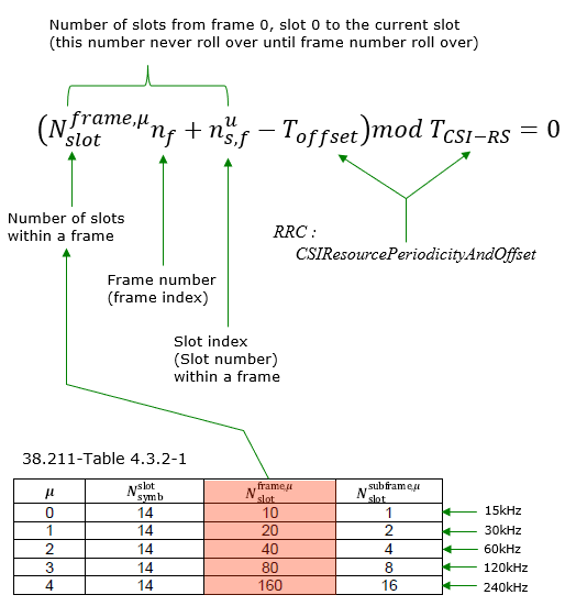
Everything up to here places CSI-RS inside one slot. That leaves the other half of the question open : which slots carry it at all. A periodic resource answers that with two numbers, a periodicity and an offset, and the equation below is how the UE turns them into slot numbers.
CSI Transmission Timing in slot is determined by RRC parameter CSI-ResourcePeriodicityAndOffset based on following equation.
It may look a little too complicated equation, but figuring out the transmission timing from RRC is pretty simple and straightforward as shown in the example below.
Example 01 >
The exact timing for a specific csi-rs is determined by periodicityAndOffset and firstOFDMSymbolInTimeDomain in RRC as shown below. The IE(Information Element) periodicityAndOffset specifies the slot level timing and firstOFDMSymbolInTimeDomain specifies symbol level timing within the slot.
periodicityAndOffset has the value in the format of slots[p]:[o]. [p] indicates the period in the unit of slots and [o] indicates the offset within the period in the unit of slots. slots40: 11 in this example means the csi-rs is transmitted at every 40 symbols with the offset of 11 slot. It means the csi-rs is transmitted at the slot (0*40+11),(1*40+11),(2*40+11) etc. In other words, it is transmitted at the slot 11, 51, 81 etc.
firstOFDMSymbolInTimeDomain indicates the symbol location within the slot where csi-rs is transmitted. For example, the value 4 as shown below indicates the csi-rs is transmitted at the symbol 4 (i.e, 5th OFDM symbol within the slot)
{
nzp-CSI-RS-ResourceId 1,
resourceMapping {
frequencyDomainAllocation row1: '1'H,
nrofPorts p1,
firstOFDMSymbolInTimeDomain 4,
cdm-Type noCDM,
density three: NULL,
freqBand {
startingRB 0,
nrofRBs 52
}
},
powerControlOffset 0,
powerControlOffsetSS db0,
scramblingID 500,
periodicityAndOffset slots40: 11,
qcl-InfoPeriodicCSI-RS 0
},
When you assign timing resources for CSI-RS, it is important to allocate it not to collide with physical resources for other physical signals (e.g, SSB) and make it sure that it falls into the downlink slot/symbol if it is TDD. My recommendation is to draw timining diagram as shown below when you first configure CSI-RS.

Image Source : Amarisoft Tech-Academy
Timing splits into two independent questions, and mixing them up is the usual source of confusion. One decides which slots carry the CSI-RS, the other decides which symbols inside that slot :
- Which slot ? – periodicityAndOffset, written as slots[p]:[o]. The resource is transmitted in a slot whenever the slot counter satisfies (slot number) mod p == o. That is all the equation is really saying.
- Which symbol ? – firstOFDMSymbolInTimeDomain, which you already met in the resource mapping section. This does not change from slot to slot.
So a CSI-RS occasion is simply 'every p slots, at offset o, on these symbols'. Note the offset is counted against the system frame and slot numbering, which is another reason the UE has to be properly synchronised before any of this works.
Resource for Interference Measurement (CSI-IM)
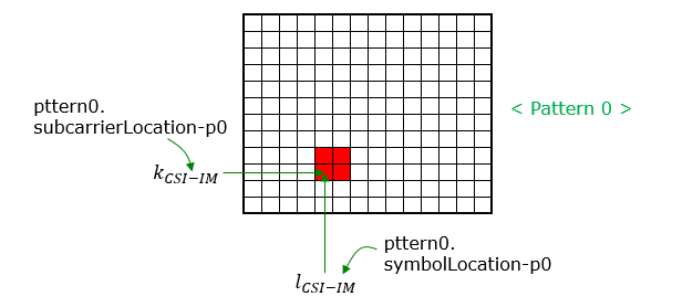
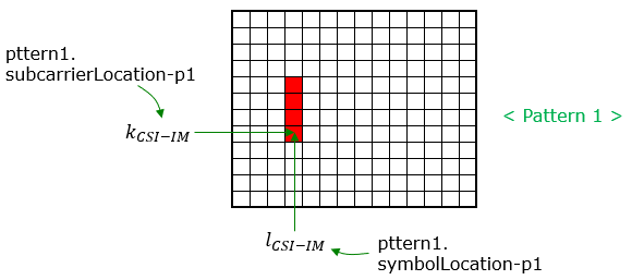
CSI IM resource is a set of specific resource elements reserved for Interference Measurement. This resources are configurable by RRC message. The frequency and time domain location is defined in 38.214 - 5.2.2.4 as illustrated below.
It is easy to skip past CSI-IM as a minor detail, but it is worth understanding why it has to exist at all. Channel quality is not an absolute signal strength – CQI is fundamentally a signal-to-interference-and-noise quantity. So the UE needs two different measurements : how strong the wanted signal is, and how strong everything else is.
NZP-CSI-RS gives the first one. CSI-IM gives the second, and it does it in an elegantly simple way : the network reserves a small set of REs and deliberately transmits nothing on them. Whatever the UE receives there cannot be from this cell, so by definition it is interference plus noise.
That leads to the single most important practical point about CSI-IM : those REs must genuinely be empty. If your own cell transmits anything at all in the CSI-IM location – data, a filler signal, anything – then the UE measures your own transmission as if it were interference. The reported CQI will still look perfectly plausible, it will simply be wrong, and nothing in the system will flag it. This is exactly the situation the ZP-CSI-RS section addresses.
You will also notice that CSI-IM offers only two patterns (pattern0 and pattern1) rather than the large table used for NZP CSI-RS. That is intentional : nothing is being transmitted here, so there are no ports and no CDM to describe. All that is needed is a location.
Following is based on
CSI-IM-Resource ::=                 SEQUENCE {
    csi-IM-ResourceId                   CSI-IM-ResourceId,
    csi-IM-ResourceElementPattern           CHOICE {
        pattern0                                SEQUENCE {
            subcarrierLocation-p0                   ENUMERATED { s0, s2, s4, s6, s8, s10 },
            symbolLocation-p0                       INTEGER (0..12)
        },
        pattern1                                SEQUENCE {
            subcarrierLocation-p1                   ENUMERATED { s0, s4, s8 },
            symbolLocation-p1                       INTEGER (0..13)
        }
    }                                                                                   OPTIONAL,   -- Need M
    freqBand                            CSI-FrequencyOccupation                         OPTIONAL,   -- Need M
    periodicityAndOffset                CSI-ResourcePeriodicityAndOffset                OPTIONAL,   -- Cond PeriodicOrSemiPersistent
    ...
}

CSI-FrequencyOccupation ::=         SEQUENCE {
    startingRB                          INTEGER (0..maxNrofPhysicalResourceBlocks-1),
    nrofRBs                             INTEGER (24..maxNrofPhysicalResourceBlocksPlus1),
    ...
}
Following is based on
CSI-FrequencyOccupation ::=         SEQUENCE {
    startingRB                          INTEGER (0..maxNrofPhysicalResourceBlocksPlus1),
    nrofRBs                             INTEGER (24..maxNrofPhysicalResourceBlocksPlus1),
    ...
}
Tracking Reference Signal (TRS)
5G TRS, or Tracking Reference Signal, is a key component in 5G wireless technology, primarily used for beam management. TRS in 5G plays a crucial role in maintaining time and frequency synchronization, particularly in high mobility scenarios, distinguishing it from CSI-RS, which is more aligned with beam management and channel quality assessment
The first thing to understand about TRS is that it is not a new physical signal. There is no separate TRS generator anywhere in the specification. A TRS is an ordinary NZP-CSI-RS resource set which happens to have trs-Info present – the same sequence generation, the same resource mapping tables, the same everything. Only the purpose and the configuration constraints differ.
Why does it need a special purpose at all ? Because a UE's local oscillator is never perfect. Over time its clock drifts, both in frequency (which shows up as a carrier frequency offset) and in time (which shows up as a sampling or timing offset). Left alone, that drift will eventually destroy demodulation. The UE therefore needs something to track against, and that is exactly what TRS is for – the name Tracking Reference Signal is quite literal.
The configuration constraints follow directly from that job, which makes them easy to remember rather than easy to forget :
- Single port – you are measuring a drift, not a spatial channel, so more ports would only add cost.
- Wide in frequency, with density three – estimating a timing offset means measuring how phase rotates across frequency, so the samples must be spread widely across the band.
- Two symbols spaced 4 apart, in each of two consecutive slots – estimating a frequency offset means measuring how phase rotates over time, so you need pairs of symbols separated by a known gap. The two spacings, 4 symbols and one slot, give both a fine and a coarse measurement.
Following is based on
NZP-CSI-RS-ResourceSet ::=          SEQUENCE {
    nzp-CSI-ResourceSetId               NZP-CSI-RS-ResourceSetId,
    nzp-CSI-RS-Resources                SEQUENCE (SIZE (1..maxNrofNZP-CSI-RS-ResourcesPerSet)) OF NZP-CSI-RS-ResourceId,
    repetition                          ENUMERATED { on, off }                                                  OPTIONAL,   -- Need S
    aperiodicTriggeringOffset           INTEGER(0..6)                                                           OPTIONAL,   -- Need S
    trs-Info                            ENUMERATED {true}                                                       OPTIONAL,   -- Need R
    ...,
    [[
    aperiodicTriggeringOffset-r16       INTEGER(0..31)                                                          OPTIONAL   -- Need S
    ]],
    [[
    pdc-Info-r17                        ENUMERATED {true}                                                       OPTIONAL,  -- Need R
    cmrGroupingAndPairing-r17           CMRGroupingAndPairing-r17                                               OPTIONAL,  -- Need R
    aperiodicTriggeringOffset-r17       INTEGER (0..124)                                                        OPTIONAL,  -- Need S
    aperiodicTriggeringOffsetL2-r17     INTEGER(0..31)                                                          OPTIONAL   -- Need R
    ]],
    [[
    resourceType-r18                    ENUMERATED {periodic}                                                   OPTIONAL   -- Cond LTM
    ]],
    [[
    kdopp-r19                           SEQUENCE {
        numberOfResourceGroups-r19          ENUMERATED {n4, n8, n12},
        numberOfResourcesPerGroup-r19       ENUMERATED {n2, n3, n4}
    }                                                                                                           OPTIONAL,  -- Need R
    additionalOneSlotOffsetDoppler-r19  CHOICE {
        twoResourcesPerGroup-r19            BIT STRING(SIZE(2)),
        threeResourcesPerGroup-r19          BIT STRING(SIZE(3)),
        fourResourcesPerGroup-r19           BIT STRING(SIZE(4))
    }                                                                                                           OPTIONAL   -- Need R
    ]]
}
38.331 defines trs-Info as follows.
38.214-5.2.2.3.1 provides additional information as follows :
trs-Info in NZP-CSI-RS-ResourceSet is associated with a CSI-RS resource set and for which the UE can assume that the antenna port with the same port index of the configured NZP CSI-RS resources in the NZP-CSI-RSResourceSet is the same as described in Subclause 5.1.6.1.1 and can be configured when reporting setting is not configured or when the higher layer parameter reportQuantity associated with all the reporting settings linked with the CSI-RS resource set is set to 'none'.
38.214-5.1.6.1.1 specifies the condition about how multiple csi-rs is grouped into a trs as stated below.
For a NZP-CSI-RS-ResourceSet configured with the higher layer parameter trs-Info, the UE shall assume the antenna
port with the same port index of the configured NZP CSI-RS resources in the NZP-CSI-RS-ResourceSet is the same.
Zero Power CSI-RS
As shown in the configuration below, in terms of resource element configuration and resource set definition it is same as NZP CSI-RS. But there are two big differences between NZP CSI-RS and ZP CSI RS as below
The name causes a lot of head scratching on first contact, so it is worth saying very directly : ZP-CSI-RS is not a signal. It is a hole. Nothing is generated, nothing is scrambled, nothing is transmitted. What is configured is a set of resource elements that the network promises to leave alone.
The reason it is described using CSI-RS machinery at all is purely practical : the thing being described is a shape on the resource grid, and the CSI-RS resource mapping tables are already an excellent way to describe shapes on a resource grid. So ZP-CSI-RS reuses them wholesale rather than inventing a second notation for the same idea.
The one thing that genuinely matters, and that the configuration placement is telling you, is who the message is for. ZP-CSI-RS lives inside PDSCH-Config, and that is not an accident. It is an instruction to the UE's PDSCH receiver, and it means : 'when you decode PDSCH, these resource elements are not carrying your data – skip them'. In other words it is a rate matching instruction. Without it the UE would happily try to decode whatever it found there and the transport block would fail its CRC.
- ZP CSI-RS is a configuration within PDSCH-Config. It means the location of ZP CSI RS would be tightly associated with the area scheduled for PDSCH.
- ZP-CSI-RS does not transmit any signal. As the term 'ZP(zero power)', this is like a 'blanked resource element' that does not transmit any signal/data.
Following is based on
PDSCH-Config ::=                        SEQUENCE {
    -- ... the fields before the ZP-CSI-RS ones are not CSI-RS related
    zp-CSI-RS-ResourceToAddModList                  SEQUENCE (SIZE (1..maxNrofZP-CSI-RS-Resources)) OF ZP-CSI-RS-Resource
    zp-CSI-RS-ResourceToReleaseList                 SEQUENCE (SIZE (1..maxNrofZP-CSI-RS-Resources)) OF ZP-CSI-RS-ResourceId
    aperiodic-ZP-CSI-RS-ResourceSetsToAddModList    SEQUENCE (SIZE (1..maxNrofZP-CSI-RS-ResourceSets)) OF ZP-CSI-RS-ResourceSet
    aperiodic-ZP-CSI-RS-ResourceSetsToReleaseList SEQUENCE (SIZE (1..maxNrofZP-CSI-RS-ResourceSets)) OF ZP-CSI-RS-ResourceSetId
    sp-ZP-CSI-RS-ResourceSetsToAddModList   SEQUENCE (SIZE (1..maxNrofZP-CSI-RS-ResourceSets)) OF ZP-CSI-RS-ResourceSet
    sp-ZP-CSI-RS-ResourceSetsToReleaseList  SEQUENCE (SIZE (1..maxNrofZP-CSI-RS-ResourceSets)) OF ZP-CSI-RS-ResourceSetId
    p-ZP-CSI-RS-ResourceSet                 SetupRelease { ZP-CSI-RS-ResourceSet }
    aperiodicZP-CSI-RS-ResourceSetsToAddModListDCI-1-2-r16  SEQUENCE (SIZE (1..maxNrofZP-CSI-RS-ResourceSets)) OF ZP-CSI-RS-ResourceSet
    aperiodicZP-CSI-RS-ResourceSetsToReleaseListDCI-1-2-r16 SEQUENCE (SIZE (1..maxNrofZP-CSI-RS-ResourceSets)) OF ZP-CSI-RS-ResourceSetId
    -- ... the remaining fields and the r16 to r19 extensions are not CSI-RS related
}

ZP-CSI-RS-Resource ::=              SEQUENCE {
    zp-CSI-RS-ResourceId                ZP-CSI-RS-ResourceId,
    resourceMapping                     CSI-RS-ResourceMapping,
    periodicityAndOffset                CSI-ResourcePeriodicityAndOffset                OPTIONAL, --Cond PeriodicOrSemiPersistent
    ...
}

ZP-CSI-RS-ResourceSet ::=           SEQUENCE {
    zp-CSI-RS-ResourceSetId             ZP-CSI-RS-ResourceSetId,
    zp-CSI-RS-ResourceIdList            SEQUENCE (SIZE(1..maxNrofZP-CSI-RS-ResourcesPerSet)) OF ZP-CSI-RS-ResourceId,
    ...
}

ZP-CSI-RS-ResourceSetId ::=                     INTEGER (0..maxNrofZP-CSI-RS-ResourceSets-1)
Why ZP CSI RS ?
In terms of configuration of ZP CSI RS, it looks clear since it is same as NZP CSI RS, but it does not look clear (at least to me) on why we need ZP CSI RS ? Why this concept is introduced ?
To be honest, this is still open question to me. So I am trying to complile various opinions in this section. If you have any different opinions, ping me via email or linkedIn.
This is the question that makes ZP-CSI-RS finally make sense, so it deserves a direct answer : you are not configuring it for the sake of the empty REs themselves. You are configuring it so that the UE's PDSCH decoder and the gNB's PDSCH encoder agree about which REs carry data. The hole is the side effect; the agreement is the point.
There are two situations where you need that agreement, and they are worth separating clearly :
- To protect somebody else's CSI-RS. A neighbouring cell, or another UE in your own cell, may have a CSI-RS in a given location. You must not transmit PDSCH over it. ZP-CSI-RS is how you punch that hole and, just as importantly, how you tell the UE that the hole is there.
- To protect your own CSI-IM. Interference measurement only works if the REs are truly empty. ZP-CSI-RS is what keeps your own PDSCH out of them – which is why a CSI-IM resource and a ZP-CSI-RS resource covering the same REs so often appear together in real configurations.
< Chat with Experts >
First I had chance to chat with Sakshama Ghoslya. He is working as L1/L2 stack developer with better knowledge than I. So the chat went as I raised question and he answered. The chat was pretty long back-and-forth but I tried to compacted as much as possible and I am sharing this with the approval of Sakshama.
[Sharetechnote] Why do we need ZP CSI-RS ? What is it designed for ? Vaguely I think it would act in a similar role as CSI-IM which can be a reference power measurement for Noise Floor(Serving cell only environment) or interference power from neighbour cells(Serving cell + neighbour cell environment).
[Sakshama] ZP-CSI-RS can be used for the following purpose:
1. Beam Mobility: gNB can configure multiple beams with identical physical layer settings and the UE finds out which beam is the best based on the power levels. For an example consider 2 adjacent beams B0 and B1. at a particular time T0, gNB can configure B0 as ZP-CSI-RS & B1 as NZP-CSI-RS and at time T1, it can configure B0 as NZP-CSI-RS & B1 as ZP-CSI-RS. This helps UE to measure CSI-RSRP individually. This helps gNB to decide (based on CQI reports) which beam to use for the UE (B0 or B1). Whether to switch or not.
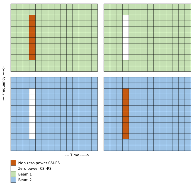
Image Source : Zero Power CSI-RS (ZP-CSI-RS) in 5G NR
2. Interference Awareness/Measurement: In this case ZP-CSI-RS is configured as CSI-IM. It allows the UE to obtain awareness of the interference. In this case gNB makes sure the ZP-CSI-RS resources are configured such that they collide with PDSCH resources of the neighbouring cells.
[Sharetechnote] Are there any other use cases you can think of ?
[Sakshama] Yes, ZP-CSI-RS can also be used for PDSCH rate matching. When a transport block is not equal to the PDSCH scheduled resources, the rate has to match. gNB can use ZP-CSI-RS resource elements to match the data rate. Configuration of ZP-CSI-RS is the same as CSI-IM, just the purpose is different.
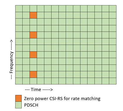
Image Source : Zero Power CSI-RS (ZP-CSI-RS) in 5G NR
< LinkedIn Post >
The quotation below comes from outside 3GPP. It is here because it puts the rate matching argument in plainer terms than the specification does. Read it as one engineer's summary rather than as normative text, and check it against the specification before you rely on it.
- Personally I tend to agree more with this view posted in LinkedIn article Deep Dive into 5G CSI RS
- On a time-domain OFDM symbol, CSI-RS for IM or NZP CSI-RS occasionally does not fully occupy the corresponding frequency-domain resources. Per specifications, ZP CSI-RS is used to inform UEs of the REs that are not mapped onto any data, as shown in the figure below. The gNodeB uses ZP CSI-RS resources to inform UEs of the remaining frequency-domain resources for mapping data, thereby increasing the number of available REs of the UEs.
< Papers/Articles >
Published papers tend to be blunter about why ZP CSI-RS exists than the specification is. A paper is free to state a purpose rather than only a behaviour. The extracts below are quoted for that reason. Each one names its source.
I want to quote statements from some papers/aritcles that I have read.
VI-C of this paper would state as follows:
Zero-power CSI-RS can be used as a masking tool to protect certain REs by making them unavailable for PDSCH mapping. This masking supports transmission of UE specific CSI-RS, but the design is also a tool for allowing introduction of new features to NR with retained backward compatibility
It is worth noting the statements from this paper :
- It should be clear that CSI-IM and ZP CSIRS have different functions, where CSI-IM defines the set of resource elements from which the interference is measured, and ZP CSI-RS defines a set of resource elements where physical downlink shared channel (PDSCH) is not mapped and UE can not make any assumptions of the content of these resources (Section III-B)-2))
- In CSI-IM method, the NZP CSI-RSs are protected from inter-cell-interference by allocating either CSI-IM or ZP CSI-RS to the REs overlapping with NZP CSI-RSs from other gNBs. This allows the UE to obtain higher quality channel measurement due to reduced interference on top of the NZP CSI-RS (Section III-B)-2))
First let look into the details of resource allocations in Fig 2 and try to understand the implications of each resource allocations.
For all cells, the symbol for DMRS are same, but further details of DMRS is not described in the paper.
[a] only NZP-CSI RS are configured for every cells (Serving gNB, gNB1, gNB2) in PDSCH regions. And the RE position of NZP CSI-RS for every cells are same. This implies that NZP CSI-RS from gNB1, gNB2 would interfere with NZP CSI RS of serving cell. In other words, NZP CSI-RS of Serving gNB is interfered by NZP CSI RS of gNB1 and gNB2. ==> This is labeld as [NZP CSI-RS non precoded IM]
[b] only NZP-CSI RS are configured for every cells (Serving gNB, gNB1, gNB2) in PDSCH regions. And the RE position of NZP CSI-RS for every cells are different in such a way that the position does not overlap with CSI-RS of any other cells. In this case, NZP CSI-RS of Serving gNB is interfered by PDSCH data RE of gNB1 and gNB2. ==> This is labeld as [NZP CSI-RS precoded IM]
[c] NZP-CSI RS and CSI-IM are configured for every cells (Serving gNB, gNB1, gNB2) in PDSCH regions. And the RE position of NZP CSI-RS for every cells are different in such a way that the position does not overlap with CSI-RS of any other cells. In this case, NZP CSI-RS of Serving gNB is NOT interfered (theoretically) by PDSCH data RE of gNB1/gNB2 nor NZP CSI-RS RE of gNB1/gNB2. ==> This is labeld as [CSI-IM non precoded IM]]
[d] NZP-CSI RS, CSI-IM and ZP CSI-RS are configured for every cells (Serving gNB, gNB1, gNB2) in PDSCH regions. And the RE position of NZP CSI-RS for every cells are different in such a way that the position does not overlap with CSI-RS of any other cells. In this configuation, the RE position of ZP CSI-RS is same as CSI-IM position of [c]. In this case, NZP CSI-RS of Serving gNB is NOT interfered (theoretically) by PDSCH data RE of gNB1/gNB2 nor NZP CSI-RS RE of gNB1/gNB2. ==> This is labeld as [CSI-IM precoded IM]]
BLER and Throughput measurement for each of the configuration are shown in Fig 3. In short, it is shown that when SINR is very good (e.g, greater than 25), you wouldn't see any differences in terms of performance regardless of which configuration you use. When SINR is poor (e.g, around cell boundary), non-precoded IM shows better performance comparing to precoded IM.
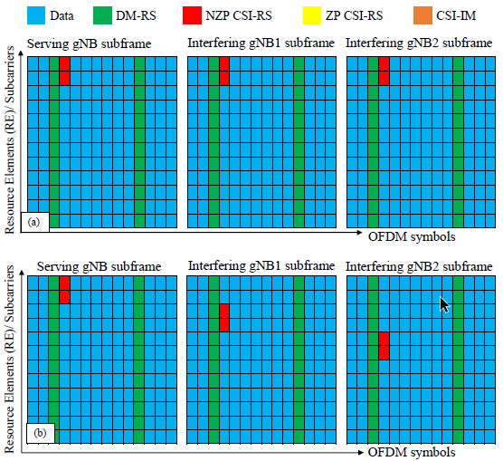
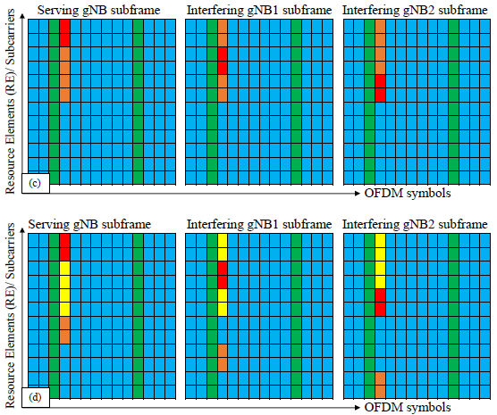
Image Source : Interference Measurement Methods in 5G NR: Principles and Performance - Fig 2
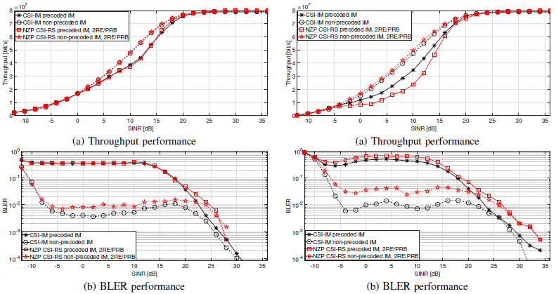
Image Source : Interference Measurement Methods in 5G NR: Principles and Performance - Fig 3
RRC Parameters for CSI RS
This section is the reference appendix for the whole page. Everything above explains one piece of the configuration at a time, and what follows puts every piece in one place, in the order RRC nests them. Use it to look things up rather than to read straight through.
The hierarchy to configure CSI-RS is pretty complicated. Overall hierachy (procedure) to configure CSI-RS can be described as follows.
The hierarchy is genuinely deep, so rather than reading it top to bottom, it helps to know that there are really two separate trees and that they meet only at the end. Once you can tell which tree you are in, navigating either one is much easier :
- The measurement tree – CSI-MeasConfig holds the NZP-CSI-RS resources, the resource sets, the CSI-IM resources, and the report configurations. This is the tree that answers 'what should the UE measure and report'.
- The scheduling tree – PDSCH-Config holds the ZP-CSI-RS resources. This is the tree that answers 'which REs should the UE's data decoder avoid'.
The four-step procedure below is really describing a movement from the smallest unit outwards : first the pattern inside one RB, then how far it extends across the band, then how often it repeats in time, and only then which tree it is attached to. If you get lost while reading a real configuration, asking 'which of these four am I looking at' usually gets you back on track quickly.
i) Configure CRS-RS resource element within single RB via CSI-RS-ResourceMapping
ii) Configure the RB locations(Start RB and N_RB) in frequency domain via CSI-RS-ResourceMapping.freqBand
iii) Configure the periodicity and offset of CSI-RS in time domain via ZP-CSI-RS-Resource and/or NZP-CSI-RS-Resource
iv) Apply the whole setting(i, ii, iii) via PDSCH-Config or/and CSI-MeasConfig
Following is based on
PDSCH-Config ::= SEQUENCE { -- ... the fields before the ZP-CSI-RS ones are not CSI-RS related zp-CSI-RS-ResourceToAddModList SEQUENCE (SIZE (1..maxNrofZP-CSI-RS-Resources)) OF ZP-CSI-RS-Resource zp-CSI-RS-ResourceToReleaseList SEQUENCE (SIZE (1..maxNrofZP-CSI-RS-Resources)) OF ZP-CSI-RS-ResourceId aperiodic-ZP-CSI-RS-ResourceSetsToAddModList SEQUENCE (SIZE (1..maxNrofZP-CSI-RS-ResourceSets)) OF ZP-CSI-RS-ResourceSet aperiodic-ZP-CSI-RS-ResourceSetsToReleaseList SEQUENCE (SIZE (1..maxNrofZP-CSI-RS-ResourceSets)) OF ZP-CSI-RS-ResourceSetId sp-ZP-CSI-RS-ResourceSetsToAddModList SEQUENCE (SIZE (1..maxNrofZP-CSI-RS-ResourceSets)) OF ZP-CSI-RS-ResourceSet sp-ZP-CSI-RS-ResourceSetsToReleaseList SEQUENCE (SIZE (1..maxNrofZP-CSI-RS-ResourceSets)) OF ZP-CSI-RS-ResourceSetId p-ZP-CSI-RS-ResourceSet SetupRelease { ZP-CSI-RS-ResourceSet } aperiodicZP-CSI-RS-ResourceSetsToAddModListDCI-1-2-r16 SEQUENCE (SIZE (1..maxNrofZP-CSI-RS-ResourceSets)) OF ZP-CSI-RS-ResourceSet aperiodicZP-CSI-RS-ResourceSetsToReleaseListDCI-1-2-r16 SEQUENCE (SIZE (1..maxNrofZP-CSI-RS-ResourceSets)) OF ZP-CSI-RS-ResourceSetId -- ... the remaining fields and the r16 to r19 extensions are not CSI-RS related } CSI-MeasConfig ::= SEQUENCE { nzp-CSI-RS-ResourceToAddModList SEQUENCE (SIZE (1..maxNrofNZP-CSI-RS-Resources)) OF NZP-CSI-RS-Resource OPTIONAL, -- Need N nzp-CSI-RS-ResourceToReleaseList SEQUENCE (SIZE (1..maxNrofNZP-CSI-RS-Resources)) OF NZP-CSI-RS-ResourceId OPTIONAL, -- Need N nzp-CSI-RS-ResourceSetToAddModList SEQUENCE (SIZE (1..maxNrofNZP-CSI-RS-ResourceSets)) OF NZP-CSI-RS-ResourceSet OPTIONAL, -- Need N nzp-CSI-RS-ResourceSetToReleaseList SEQUENCE (SIZE (1..maxNrofNZP-CSI-RS-ResourceSets)) OF NZP-CSI-RS-ResourceSetId OPTIONAL, -- Need N csi-IM-ResourceToAddModList SEQUENCE (SIZE (1..maxNrofCSI-IM-Resources)) OF CSI-IM-Resource OPTIONAL, -- Need N csi-IM-ResourceToReleaseList SEQUENCE (SIZE (1..maxNrofCSI-IM-Resources)) OF CSI-IM-ResourceId OPTIONAL, -- Need N csi-IM-ResourceSetToAddModList SEQUENCE (SIZE (1..maxNrofCSI-IM-ResourceSets)) OF CSI-IM-ResourceSet OPTIONAL, -- Need N csi-IM-ResourceSetToReleaseList SEQUENCE (SIZE (1..maxNrofCSI-IM-ResourceSets)) OF CSI-IM-ResourceSetId OPTIONAL, -- Need N csi-SSB-ResourceSetToAddModList SEQUENCE (SIZE (1..maxNrofCSI-SSB-ResourceSets)) OF CSI-SSB-ResourceSet OPTIONAL, -- Need N csi-SSB-ResourceSetToReleaseList SEQUENCE (SIZE (1..maxNrofCSI-SSB-ResourceSets)) OF CSI-SSB-ResourceSetId OPTIONAL, -- Need N csi-ResourceConfigToAddModList SEQUENCE (SIZE (1..maxNrofCSI-ResourceConfigurations)) OF CSI-ResourceConfig OPTIONAL, -- Need N csi-ResourceConfigToReleaseList SEQUENCE (SIZE (1..maxNrofCSI-ResourceConfigurations)) OF CSI-ResourceConfigId OPTIONAL, -- Need N csi-ReportConfigToAddModList SEQUENCE (SIZE (1..maxNrofCSI-ReportConfigurations)) OF CSI-ReportConfig OPTIONAL, -- Need N csi-ReportConfigToReleaseList SEQUENCE (SIZE (1..maxNrofCSI-ReportConfigurations)) OF CSI-ReportConfigId OPTIONAL, -- Need N reportTriggerSize INTEGER (0..6) OPTIONAL, -- Need M aperiodicTriggerStateList SetupRelease { CSI-AperiodicTriggerStateList } OPTIONAL, -- Need M semiPersistentOnPUSCH-TriggerStateList SetupRelease { CSI-SemiPersistentOnPUSCH-TriggerStateList } OPTIONAL, -- Need M ..., [[ reportTriggerSizeDCI-0-2-r16 INTEGER (0..6) OPTIONAL -- Need R ]], [[ sCellActivationRS-ConfigToAddModList-r17 SEQUENCE (SIZE (1..maxNrofSCellActRS-r17)) OF SCellActivationRS-Config-r17 OPTIONAL, -- Need N sCellActivationRS-ConfigToReleaseList-r17 SEQUENCE (SIZE (1..maxNrofSCellActRS-r17)) OF SCellActivationRS-ConfigId-r17 OPTIONAL -- Need N ]], [[ ltm-CSI-ReportConfigToAddModList-r18 SEQUENCE (SIZE (1..maxNrofLTM-CSI-ReportConfigurations-r18)) OF LTM-CSI-ReportConfig-r18 OPTIONAL, -- Need N ltm-CSI-ReportConfigToReleaseList-r18 SEQUENCE (SIZE (1..maxNrofLTM-CSI-ReportConfigurations-r18)) OF LTM-CSI-ReportConfigId-r18 OPTIONAL -- Need N ]], [[ cli-RSSI-MeasResourceToAddModList-r19 SEQUENCE (SIZE (1..maxNrofCLI-RSSI-MeasResources-r19)) OF CLI-RSSI-MeasResource-r19 OPTIONAL, -- Need N cli-RSSI-MeasResourceToReleaseList-r19 SEQUENCE (SIZE (1..maxNrofCLI-RSSI-MeasResources-r19)) OF CLI-RSSI-MeasResourceId-r19 OPTIONAL, -- Need N cli-RSSI-MeasResourceSetToAddModList-r19 SEQUENCE (SIZE (1..maxNrofCLI-RSSI-MeasResourceSets-r19)) OF CLI-RSSI-MeasResourceSet-r19 OPTIONAL, -- Need N cli-RSSI-MeasResourceSetToReleaseList-r19 SEQUENCE (SIZE (1..maxNrofCLI-RSSI-MeasResourceSets-r19)) OF CLI-RSSI-MeasResourceSetId-r19 OPTIONAL, -- Need N srs-RSRP-MeasResourceToAddModList-r19 SEQUENCE (SIZE (1..maxNrofSRS-RSRP-MeasResources-r19)) OF SRS-RSRP-MeasResource-r19 OPTIONAL, -- Need N srs-RSRP-MeasResourceToReleaseList-r19 SEQUENCE (SIZE (1..maxNrofSRS-RSRP-MeasResources-r19)) OF SRS-RSRP-MeasResourceId-r19 OPTIONAL, -- Need N srs-RSRP-MeasResourceSetToAddModList-r19 SEQUENCE (SIZE (1..maxNrofSRS-RSRP-MeasResourceSets-r19)) OF SRS-RSRP-MeasResourceSet-r19 OPTIONAL, -- Need N srs-RSRP-MeasResourceSetToReleaseList-r19 SEQUENCE (SIZE (1..maxNrofSRS-RSRP-MeasResourceSets-r19)) OF SRS-RSRP-MeasResourceSetId-r19 OPTIONAL, -- Need N csi-LoggedMeasurementConfigToAddModList-r19 SEQUENCE (SIZE (1..maxNrofLoggedMeasurementConfigurations-r19)) OF CSI-LoggedMeasurementConfig-r19 OPTIONAL, -- Need N csi-LoggedMeasurementConfigToReleaseList-r19 SEQUENCE (SIZE (1..maxNrofLoggedMeasurementConfigurations-r19)) OF CSI-LoggedMeasurementConfigId-r19 OPTIONAL -- Need N ]] } ZP-CSI-RS-Resource ::= SEQUENCE { zp-CSI-RS-ResourceId ZP-CSI-RS-ResourceId, resourceMapping CSI-RS-ResourceMapping, periodicityAndOffset CSI-ResourcePeriodicityAndOffset OPTIONAL, --Cond PeriodicOrSemiPersistent ... } ZP-CSI-RS-ResourceSet ::= SEQUENCE { zp-CSI-RS-ResourceSetId ZP-CSI-RS-ResourceSetId, zp-CSI-RS-ResourceIdList SEQUENCE (SIZE(1..maxNrofZP-CSI-RS-ResourcesPerSet)) OF ZP-CSI-RS-ResourceId, ... } NZP-CSI-RS-Resource ::= SEQUENCE { nzp-CSI-RS-ResourceId NZP-CSI-RS-ResourceId, resourceMapping CSI-RS-ResourceMapping, powerControlOffset INTEGER (-8..15), powerControlOffsetSS ENUMERATED{db-3, db0, db3, db6} OPTIONAL, -- Need R scramblingID ScramblingId, periodicityAndOffset CSI-ResourcePeriodicityAndOffset OPTIONAL, -- Cond PeriodicOrSemiPersistent qcl-InfoPeriodicCSI-RS TCI-StateId OPTIONAL, -- Cond Periodic ..., [[ subcarrierSpacing-r18 SubcarrierSpacing OPTIONAL, -- Cond LTM absoluteFrequencyPointA-r18 ARFCN-ValueNR OPTIONAL, -- Cond LTM cyclicPrefix-r18 ENUMERATED {extended} OPTIONAL -- Cond LTM ]], [[ additionalOneSlotOffset-r19 ENUMERATED{enabled} OPTIONAL, -- Need R additionalSlotOffset-r19 INTEGER(0..7) OPTIONAL -- Need R ]] } NZP-CSI-RS-ResourceSet ::= SEQUENCE { nzp-CSI-ResourceSetId NZP-CSI-RS-ResourceSetId, nzp-CSI-RS-Resources SEQUENCE (SIZE (1..maxNrofNZP-CSI-RS-ResourcesPerSet)) OF NZP-CSI-RS-ResourceId, repetition ENUMERATED { on, off } OPTIONAL, -- Need S aperiodicTriggeringOffset INTEGER(0..6) OPTIONAL, -- Need S trs-Info ENUMERATED {true} OPTIONAL, -- Need R ..., [[ aperiodicTriggeringOffset-r16 INTEGER(0..31) OPTIONAL -- Need S ]], [[ pdc-Info-r17 ENUMERATED {true} OPTIONAL, -- Need R cmrGroupingAndPairing-r17 CMRGroupingAndPairing-r17 OPTIONAL, -- Need R aperiodicTriggeringOffset-r17 INTEGER (0..124) OPTIONAL, -- Need S aperiodicTriggeringOffsetL2-r17 INTEGER(0..31) OPTIONAL -- Need R ]], [[ resourceType-r18 ENUMERATED {periodic} OPTIONAL -- Cond LTM ]], [[ kdopp-r19 SEQUENCE { numberOfResourceGroups-r19 ENUMERATED {n4, n8, n12}, numberOfResourcesPerGroup-r19 ENUMERATED {n2, n3, n4} } OPTIONAL, -- Need R additionalOneSlotOffsetDoppler-r19 CHOICE { twoResourcesPerGroup-r19 BIT STRING(SIZE(2)), threeResourcesPerGroup-r19 BIT STRING(SIZE(3)), fourResourcesPerGroup-r19 BIT STRING(SIZE(4)) } OPTIONAL -- Need R ]] } CSI-RS-ResourceMapping ::= SEQUENCE { frequencyDomainAllocation CHOICE { row1 BIT STRING (SIZE (4)), row2 BIT STRING (SIZE (12)), row4 BIT STRING (SIZE (3)), other BIT STRING (SIZE (6)) }, nrofPorts ENUMERATED {p1,p2,p4,p8,p12,p16,p24,p32}, firstOFDMSymbolInTimeDomain INTEGER (0..13), firstOFDMSymbolInTimeDomain2 INTEGER (2..12) OPTIONAL, -- Need R cdm-Type ENUMERATED {noCDM, fd-CDM2, cdm4-FD2-TD2, cdm8-FD2-TD4}, density CHOICE { dot5 ENUMERATED {evenPRBs, oddPRBs}, one NULL, three NULL, spare NULL }, freqBand CSI-FrequencyOccupation, ... } CSI-ResourcePeriodicityAndOffset ::= CHOICE { slots4 INTEGER (0..3), slots5 INTEGER (0..4), slots8 INTEGER (0..7), slots10 INTEGER (0..9), slots16 INTEGER (0..15), slots20 INTEGER (0..19), slots32 INTEGER (0..31), slots40 INTEGER (0..39), slots64 INTEGER (0..63), slots80 INTEGER (0..79), slots160 INTEGER (0..159), slots320 INTEGER (0..319), slots640 INTEGER (0..639) } CSI-FrequencyOccupation ::= SEQUENCE { startingRB INTEGER (0..maxNrofPhysicalResourceBlocks-1), nrofRBs INTEGER (24..maxNrofPhysicalResourceBlocksPlus1), ... } CSI-IM-Resource ::= SEQUENCE { csi-IM-ResourceId CSI-IM-ResourceId, csi-IM-ResourceElementPattern CHOICE { pattern0 SEQUENCE { subcarrierLocation-p0 ENUMERATED { s0, s2, s4, s6, s8, s10 }, symbolLocation-p0 INTEGER (0..12) }, pattern1 SEQUENCE { subcarrierLocation-p1 ENUMERATED { s0, s4, s8 }, symbolLocation-p1 INTEGER (0..13) } } OPTIONAL, -- Need M freqBand CSI-FrequencyOccupation OPTIONAL, -- Need M periodicityAndOffset CSI-ResourcePeriodicityAndOffset OPTIONAL, -- Cond PeriodicOrSemiPersistent ... } CSI-IM-ResourceSet ::= SEQUENCE { csi-IM-ResourceSetId CSI-IM-ResourceSetId, csi-IM-Resources SEQUENCE (SIZE(1..maxNrofCSI-IM-ResourcesPerSet)) OF CSI-IM-ResourceId, ... } CSI-SSB-ResourceSet ::= SEQUENCE { csi-SSB-ResourceSetId CSI-SSB-ResourceSetId, csi-SSB-ResourceList SEQUENCE (SIZE(1..maxNrofCSI-SSB-ResourcePerSet)) OF SSB-Index, ..., [[ servingAdditionalPCIList-r17 SEQUENCE (SIZE(1..maxNrofCSI-SSB-ResourcePerSet)) OF ServingAdditionalPCIIndex-r17 OPTIONAL -- Need R ]] } CSI-ResourceConfig ::= SEQUENCE { csi-ResourceConfigId CSI-ResourceConfigId, csi-RS-ResourceSetList CHOICE { nzp-CSI-RS-SSB SEQUENCE { nzp-CSI-RS-ResourceSetList SEQUENCE (SIZE (1..maxNrofNZP-CSI-RS-ResourceSetsPerConfig)) OF NZP-CSI-RS-ResourceSetId OPTIONAL, -- Need R csi-SSB-ResourceSetList SEQUENCE (SIZE (1..maxNrofCSI-SSB-ResourceSetsPerConfig)) OF CSI-SSB-ResourceSetId OPTIONAL -- Need R }, csi-IM-ResourceSetList SEQUENCE (SIZE (1..maxNrofCSI-IM-ResourceSetsPerConfig)) OF CSI-IM-ResourceSetId }, bwp-Id BWP-Id, resourceType ENUMERATED { aperiodic, semiPersistent, periodic }, ..., [[ csi-SSB-ResourceSetListExt-r17 CSI-SSB-ResourceSetId OPTIONAL -- Need R ]], [[ cli-MeasResourceSetList-r19 CHOICE { cli-RSSI-MeasResourceSetList-r19 SEQUENCE (SIZE (1..maxNrofCLI-RSSI-MeasResourceSetsPerConfig-r19)) OF CLI-RSSI-MeasResourceSetId-r19, srs-RSRP-MeasResourceSetList-r19 SEQUENCE (SIZE (1..maxNrofSRS-RSRP-MeasResourceSetsPerConfig-r19)) OF SRS-RSRP-MeasResourceSetId-r19, ... } OPTIONAL -- Need R ]] } CSI-ReportConfig ::= SEQUENCE { reportConfigId CSI-ReportConfigId, carrier ServCellIndex OPTIONAL, -- Need S resourcesForChannelMeasurement CSI-ResourceConfigId, csi-IM-ResourcesForInterference CSI-ResourceConfigId OPTIONAL, -- Need R nzp-CSI-RS-ResourcesForInterference CSI-ResourceConfigId OPTIONAL, -- Need R reportConfigType CHOICE { periodic SEQUENCE { reportSlotConfig CSI-ReportPeriodicityAndOffset, pucch-CSI-ResourceList SEQUENCE (SIZE (1..maxNrofBWPs)) OF PUCCH-CSI-Resource }, semiPersistentOnPUCCH SEQUENCE { reportSlotConfig CSI-ReportPeriodicityAndOffset, pucch-CSI-ResourceList SEQUENCE (SIZE (1..maxNrofBWPs)) OF PUCCH-CSI-Resource }, semiPersistentOnPUSCH SEQUENCE { reportSlotConfig ENUMERATED {sl5, sl10, sl20, sl40, sl80, sl160, sl320}, reportSlotOffsetList SEQUENCE (SIZE (1.. maxNrofUL-Allocations)) OF INTEGER(0..32), p0alpha P0-PUSCH-AlphaSetId }, aperiodic SEQUENCE { reportSlotOffsetList SEQUENCE (SIZE (1..maxNrofUL-Allocations)) OF INTEGER(0..32) } }, reportQuantity CHOICE { none NULL, cri-RI-PMI-CQI NULL, cri-RI-i1 NULL, cri-RI-i1-CQI SEQUENCE { pdsch-BundleSizeForCSI ENUMERATED {n2, n4} OPTIONAL -- Need S }, cri-RI-CQI NULL, cri-RSRP NULL, ssb-Index-RSRP NULL, cri-RI-LI-PMI-CQI NULL }, reportFreqConfiguration SEQUENCE { cqi-FormatIndicator ENUMERATED { widebandCQI, subbandCQI } OPTIONAL, -- Need R pmi-FormatIndicator ENUMERATED { widebandPMI, subbandPMI } OPTIONAL, -- Need R csi-ReportingBand CHOICE { subbands3 BIT STRING(SIZE(3)), subbands4 BIT STRING(SIZE(4)), subbands5 BIT STRING(SIZE(5)), subbands6 BIT STRING(SIZE(6)), subbands7 BIT STRING(SIZE(7)), subbands8 BIT STRING(SIZE(8)), subbands9 BIT STRING(SIZE(9)), subbands10 BIT STRING(SIZE(10)), subbands11 BIT STRING(SIZE(11)), subbands12 BIT STRING(SIZE(12)), subbands13 BIT STRING(SIZE(13)), subbands14 BIT STRING(SIZE(14)), subbands15 BIT STRING(SIZE(15)), subbands16 BIT STRING(SIZE(16)), subbands17 BIT STRING(SIZE(17)), subbands18 BIT STRING(SIZE(18)), ..., subbands19-v1530 BIT STRING(SIZE(19)) } OPTIONAL -- Need S } OPTIONAL, -- Need R timeRestrictionForChannelMeasurements ENUMERATED {configured, notConfigured}, timeRestrictionForInterferenceMeasurements ENUMERATED {configured, notConfigured}, codebookConfig CodebookConfig OPTIONAL, -- Need R dummy ENUMERATED {n1, n2} OPTIONAL, -- Need R groupBasedBeamReporting CHOICE { enabled NULL, disabled SEQUENCE { nrofReportedRS ENUMERATED {n1, n2, n3, n4} OPTIONAL -- Need S } }, cqi-Table CQI-Table OPTIONAL, -- Need R subbandSize ENUMERATED {value1, value2}, non-PMI-PortIndication SEQUENCE (SIZE (1..maxNrofNZP-CSI-RS-ResourcesPerConfig)) OF PortIndexFor8Ranks OPTIONAL, -- Need R ..., -- ... the Release 16 to 19 extension groups are not shown here } CSI-ReportPeriodicityAndOffset ::= CHOICE { slots4 INTEGER(0..3), slots5 INTEGER(0..4), slots8 INTEGER(0..7), slots10 INTEGER(0..9), slots16 INTEGER(0..15), slots20 INTEGER(0..19), slots40 INTEGER(0..39), slots80 INTEGER(0..79), slots160 INTEGER(0..159), slots320 INTEGER(0..319) } PUCCH-CSI-Resource ::= SEQUENCE { uplinkBandwidthPartId BWP-Id, pucch-Resource PUCCH-ResourceId } PortIndexFor8Ranks ::= CHOICE { portIndex8 SEQUENCE{ rank1-8 PortIndex8 OPTIONAL, -- Need R rank2-8 SEQUENCE(SIZE(2)) OF PortIndex8 OPTIONAL, -- Need R rank3-8 SEQUENCE(SIZE(3)) OF PortIndex8 OPTIONAL, -- Need R rank4-8 SEQUENCE(SIZE(4)) OF PortIndex8 OPTIONAL, -- Need R rank5-8 SEQUENCE(SIZE(5)) OF PortIndex8 OPTIONAL, -- Need R rank6-8 SEQUENCE(SIZE(6)) OF PortIndex8 OPTIONAL, -- Need R rank7-8 SEQUENCE(SIZE(7)) OF PortIndex8 OPTIONAL, -- Need R rank8-8 SEQUENCE(SIZE(8)) OF PortIndex8 OPTIONAL -- Need R }, portIndex4 SEQUENCE{ rank1-4 PortIndex4 OPTIONAL, -- Need R rank2-4 SEQUENCE(SIZE(2)) OF PortIndex4 OPTIONAL, -- Need R rank3-4 SEQUENCE(SIZE(3)) OF PortIndex4 OPTIONAL, -- Need R rank4-4 SEQUENCE(SIZE(4)) OF PortIndex4 OPTIONAL -- Need R }, portIndex2 SEQUENCE{ rank1-2 PortIndex2 OPTIONAL, -- Need R rank2-2 SEQUENCE(SIZE(2)) OF PortIndex2 OPTIONAL -- Need R }, portIndex1 NULL } CodebookConfig ::= SEQUENCE { codebookType CHOICE { type1 SEQUENCE { subType CHOICE { typeI-SinglePanel SEQUENCE { nrOfAntennaPorts CHOICE { two SEQUENCE { twoTX-CodebookSubsetRestriction BIT STRING (SIZE (6)) }, moreThanTwo SEQUENCE { n1-n2 CHOICE { two-one-TypeI-SinglePanel-Restriction BIT STRING (SIZE (8)), two-two-TypeI-SinglePanel-Restriction BIT STRING (SIZE (64)), four-one-TypeI-SinglePanel-Restriction BIT STRING (SIZE (16)), three-two-TypeI-SinglePanel-Restriction BIT STRING (SIZE (96)), six-one-TypeI-SinglePanel-Restriction BIT STRING (SIZE (24)), four-two-TypeI-SinglePanel-Restriction BIT STRING (SIZE (128)), eight-one-TypeI-SinglePanel-Restriction BIT STRING (SIZE (32)), four-three-TypeI-SinglePanel-Restriction BIT STRING (SIZE (192)), six-two-TypeI-SinglePanel-Restriction BIT STRING (SIZE (192)), twelve-one-TypeI-SinglePanel-Restriction BIT STRING (SIZE (48)), four-four-TypeI-SinglePanel-Restriction BIT STRING (SIZE (256)), eight-two-TypeI-SinglePanel-Restriction BIT STRING (SIZE (256)), sixteen-one-TypeI-SinglePanel-Restriction BIT STRING (SIZE (64)) }, typeI-SinglePanel-codebookSubsetRestriction-i2 BIT STRING (SIZE (16)) OPTIONAL -- Need R } }, typeI-SinglePanel-ri-Restriction BIT STRING (SIZE (8)) }, typeI-MultiPanel SEQUENCE { ng-n1-n2 CHOICE { two-two-one-TypeI-MultiPanel-Restriction BIT STRING (SIZE (8)), two-four-one-TypeI-MultiPanel-Restriction BIT STRING (SIZE (16)), four-two-one-TypeI-MultiPanel-Restriction BIT STRING (SIZE (8)), two-two-two-TypeI-MultiPanel-Restriction BIT STRING (SIZE (64)), two-eight-one-TypeI-MultiPanel-Restriction BIT STRING (SIZE (32)), four-four-one-TypeI-MultiPanel-Restriction BIT STRING (SIZE (16)), two-four-two-TypeI-MultiPanel-Restriction BIT STRING (SIZE (128)), four-two-two-TypeI-MultiPanel-Restriction BIT STRING (SIZE (64)) }, ri-Restriction BIT STRING (SIZE (4)) } }, codebookMode INTEGER (1..2) }, type2 SEQUENCE { subType CHOICE { typeII SEQUENCE { n1-n2-codebookSubsetRestriction CHOICE { two-one BIT STRING (SIZE (16)), two-two BIT STRING (SIZE (43)), four-one BIT STRING (SIZE (32)), three-two BIT STRING (SIZE (59)), six-one BIT STRING (SIZE (48)), four-two BIT STRING (SIZE (75)), eight-one BIT STRING (SIZE (64)), four-three BIT STRING (SIZE (107)), six-two BIT STRING (SIZE (107)), twelve-one BIT STRING (SIZE (96)), four-four BIT STRING (SIZE (139)), eight-two BIT STRING (SIZE (139)), sixteen-one BIT STRING (SIZE (128)) }, typeII-RI-Restriction BIT STRING (SIZE (2)) }, typeII-PortSelection SEQUENCE { portSelectionSamplingSize ENUMERATED {n1, n2, n3, n4} OPTIONAL, -- Need R typeII-PortSelectionRI-Restriction BIT STRING (SIZE (2)) } }, phaseAlphabetSize ENUMERATED {n4, n8}, subbandAmplitude BOOLEAN, numberOfBeams ENUMERATED {two, three, four} } } }
RRC Examples
Following is a simple example of CSI-RS allocation from 38.508-1. You would have more details configurations from the same specification that I summarized in this note.
< Based on 38.508-1 Table 4.6.3-45: CSI-RS-ResourceMapping >
Reading a real configuration is a different skill from reading the specification, and it is the skill you actually need on the job. The specification tells you what every field can be; a real message tells you what somebody chose, and usually the interesting question is why they chose it.
A practical order to read any CSI-RS configuration you meet in the field :
- Start at the resource, not the top. Find nrofPorts, cdm-Type and density, and use them to fix the row in the table. Everything else is easier once the row is known.
- Then resolve the position. Read the bitmap and firstOFDMSymbolInTimeDomain, and work out the actual k and l values.
- Then resolve the timing. Read periodicityAndOffset and convert it to a real interval – remembering it is counted in slots, not milliseconds.
- Finally, look upwards. Find which resource set contains it, and which report configuration refers to that set. This is what tells you the purpose : a set with trs-Info is tracking, a set referenced by a cri-RI-PMI-CQI report is channel measurement.
|
|
TRS |
FR1 |
FR2 |
|
CSI-RS-ResourceMapping ::= SEQUENCE { frequencyDomainAllocation CHOICE { |
|
|
|
|
row1 |
1000 |
|
|
|
row4 |
|
|
010 |
|
other |
|
011110 |
|
|
} |
|
|
|
|
nrofPorts |
p1 |
p8 |
p4 |
|
firstOFDMSymbolInTimeDomain |
4 |
3 |
13 |
|
firstOFDMSymbolInTimeDomain2 |
Not present |
|
|
|
cdm-Type |
noCDM |
fd-CDM2 |
fd-CDM2 |
|
density CHOICE { |
|
|
|
|
one |
|
|
|
|
three |
NULL |
|
|
|
} |
|
|
|
|
freqBand |
|
|
|
|
} |
|
|
|
| NOTE | see here for CSI-RS map | see here for CSI-RS map |
< Based on 38.508-1 Table 4.6.3-33: CSI-FrequencyOccupation >
|
|
FR1_60 |
FR1_80 |
FR1_100 |
FR2_100 |
TRS |
|
CSI-FrequencyOccupation ::= SEQUENCE { |
|
|
|
|
|
|
startingRB |
0 |
0 |
0 |
0 |
0 |
|
nrofRBs |
160 |
216 |
272 |
64 |
52 |
|
} |
How to Avoid Collision with Other Signals ?
According to what is explained above, it would be possible to allocate the CSI-RS at any symbol and in any slot, but in real situation where various other physical channels and signals running we cannot enjoy such a full degree of freedom for allocating CSI-RS. In this aspect, I think I can list some tips that may helps.
This section is about a consequence of everything above, and it is the most practical part of the page. The flexibility that makes CSI-RS powerful also makes it dangerous : the specification will happily let you configure a CSI-RS in a location that is already spoken for, and nothing will warn you.
The reason collisions matter so much is worth stating explicitly. A CSI-RS does not politely share a resource element – it replaces whatever was there. So a badly placed CSI-RS does not produce an error; it produces damage somewhere else :
- Overlap the SSB and you may disturb the very signal UEs rely on to synchronise and to measure RSRP.
- Overlap CORESET/PDCCH and the UE may miss its scheduling grants – which then looks like a coverage problem rather than a configuration problem.
- Overlap PDSCH DMRS and channel estimation degrades, so the data fails to decode even though the signal is strong.
- Overlap PDSCH data without a matching ZP-CSI-RS and the transport block simply fails CRC, with every RF measurement still looking perfectly healthy.
- Place it in an uplink symbol of a TDD pattern and it will not be transmitted at all.
Notice the common thread : in every one of these cases the radio looks fine and something else breaks. That indirectness is exactly why collision avoidance is worth doing carefully up front rather than debugging afterwards. The tips below are the practical checklist.
- Avoid Symbols where SSB is transmitted
- Avoid slots and symbols that are configured for Uplink in TDD UL-DL configuration
- Avoid symbols where CORESET is configured
- Avoid symbols where PDSCH DMRS is configured
Example 1 >
The collision problem is easiest to see with real numbers, so the configuration below is a concrete one. Watch the SSB positions and the CSI-RS symbols in particular, because those are the two things that have to be checked against each other.
As an example, let's assume a case as follows.
SIB 1 :
ssb-PositionsInBurst {
inOneGroup 'FF'H
},
ssb-PeriodicityServingCell ms20,
tdd-UL-DL-ConfigurationCommon {
referenceSubcarrierSpacing kHz30,
pattern1 {
dl-UL-TransmissionPeriodicity ms5,
nrofDownlinkSlots 7,
nrofDownlinkSymbols 6,
nrofUplinkSlots 2,
nrofUplinkSymbols 4
}
},
First thing I want to suggest you to do is to draw a diagram and mark the configuration of ssb bitmap and tdd-UL-DL config and some additional symbols where CSI-RS is not allowed to be assigned as below.
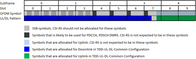
Now you have a bunck of white spaces where you can allocate CSI-RS. Not so many white spaces, right ? Actually if you want to put the CSI-RS to another 5ms period where SSB is not transmitted, it would be much easier to configure, but in this example I intentionaly picked up tough situation. There can be so many different ways of configuring the CSI-RS, but you can determine any valid configuration as you want and mark it as shown below (this is just one example) and then populate the configuration into RRC message. It would be very error prone if you try configuring RRC without this kind of drawing beforehand.
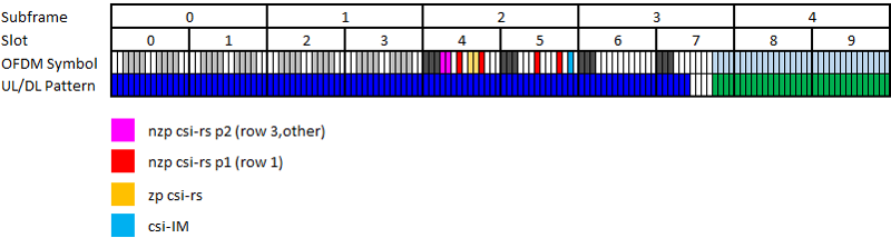
Reference
The material below goes beyond what this page covers, and it is worth knowing what each source is good for. The 3GPP specifications are the authority for the tables and the exact field definitions – 38.211 for sequence generation and resource mapping, 38.214 for the measurement and CSI-IM behaviour, and 38.331 for every RRC parameter mentioned here. The papers and articles are more useful for the reasoning : why interference measurement is designed the way it is, and how these signals behave in real deployments rather than on paper.
- Interference Measurement Methods in 5G NR:Principles and Performance - ResearchGate
- 5G New Radio: Unveiling the Essentials of the Next Generation Wireless Access Technology - arxiv
- An Introduction to CSI-RS - NR LTE Blog
- Deep-Dive into 5G CSI-RS - LinkedIn