N1 interface(Reference Point) indicates the connection between UE and AMF mainly for NAS layer signaling, but the exact role of N1 interface (reference point) is a little bit ambiguous to me.
- What is N1 Interface ?
- What is N1 mode ?
- 3GPP Statements on N1 interface/refernce point
- UE Capability for N1mode Support
What is N1 Interface ?
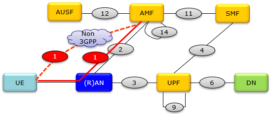
According to 23.501-Figure 4.2.4-4, N1 reference point (labeled as '1') is indicated as follows. It seems obvious that N1 is the interface between UE and AMF, but there is no access network along N1. So I was wondering how UE can get access to AMF without access network.

With further looking at other parts of the document (like figures in section 23.501-4.2.8.2 and description at 23.501-5.3.3.1), it seems that N1 interface represent the interface as follows. At least for now, my understanding is as follows.
- N1 is the interface between UE and AMF
- N1 represents the combined path UE <--> Access Network and Access Network <--> AMF
- The Access Network can be a 3GPP based (e.g, gNB) or non 3GPP based.
- Most of NAS signaling is going through N1
There is another statement from 24.501-3.1 writing the definition of N1 NAS signalling connection as follows.
What is N1 mode ?
In addition to N1 reference point/interface with the focus on physical connections in the overal network architecture, there is another term called N1 mode which is more focused on functional point of view (especially with the perspective of NAS signaling).
The formal definition of N1 mode is defined in 24.501-3.1 as follows
N1 mode refers to the 5G standalone architecture where the 5G core network connects directly to the 5G radio access network, without involvement of the 4G EPC core. N1 mode is the standalone deployment where the 5G radio connects directly to the 5G core network over the N1 interface to leverage the complete 5G system capabilities
- The interface between the 5G RAN and 5G Core is called N1. This replaces the S1 interface used in 4G networks.
- In N1 mode, the UE connects directly to core network functions like AMF, SMF, UPF using the 5G radio and protocol stack. No anchoring via 4G is needed.
- The NG and Xn interfaces are used within the 5G RAN for control plane and user plane signaling. There is no dependence on 4G interfaces.
- N1 mode allows the network to leverage core 5G features like network slicing, QoS flow management, advanced RAN capabilities etc.
- 5G devices primarily support N1 mode for optimal performance, but they also support Non-standalone mode (with LTE anchor) for compatibility.
- N1 mode simplifies the network architecture compared to NSA mode. But it requires deploying a full 5G core network first.
UE Usage state and N1 disable/enable
When N1 mode enabled or disabled on UE side. There are specific conditions that enable / disable the mode and those conditions are specified in 24.501
Following table is based on 24.501 - 4.3.3.1, 4.3.4.1 and 4.9. I changed the format for better / quictly to be used as a cheat sheet -:)
|
UE Usage Setting |
Network Capability |
Registration Status |
N1 mode status |
| Power Cycle (Off --> On) | |||
| USIM Removal | |||
| Disable ->Timer Expiration(*1) | |||
|
From "data centric" to "voice centric" |
"IMS voice not available" over 3GPP access only |
the UE is only registered over 3GPP access |
|
|
From "data centric" to "voice centric" |
"IMS voice not available" over both 3GPP access and non-3GPP access |
the UE is registered over both 3GPP access and non-3GPP access |
|
|
From "data centric" to "voice centric" |
"IMS voice not available" over both 3GPP access and non-3GPP access |
the UE is registered over 3GPP access only |
|
|
From "data centric" to "voice centric" |
"IMS voice not available" over both 3GPP access and non-3GPP access |
the UE is registered over non-3GPP access only. |
|
|
From "voice centric" to "data centric" |
N1 mode capability for 3GPP access is disabled at the UE (due to IMS voice unavailability) |
|
|
|
From "data centric" to "voice centric" |
"IMS voice not available" over non-3GPP access only |
the UE is only registered over non-3GPP access |
|
|
From "voice centric" to "data centric" |
N1 mode capability for non 3GPP access is disabled at the UE (due to IMS voice unavailability) |
|
|
|
"voice centric" |
"IMS voice not available" over 3GPP access only |
the UE is only registered over 3GPP access |
|
|
"voice centric" |
"IMS voice not available" over non-3GPP access only |
|
|
|
"voice centric" |
"IMS voice not available" over both 3GPP access and non-3GPP access |
UE is registered over both 3GPP access and non-3GPP access. |
|
|
"voice centric" |
"IMS voice not available" over both 3GPP access and non-3GPP access |
UE is registered over 3GPP access only |
|
|
"voice centric" |
"IMS voice not available" over both 3GPP access and non-3GPP access |
UE is registered over non-3GPP access only. |
|
Let's summarize the table in a little bit different format.
- When UE usage setting changes
from data centric to voice centric : - If IMS voice unavailable on 3GPP, N1
disabled for 3GPP. - If IMS voice unavailable on non-3GPP, N1
disabledfor non-3GPP. - If IMS voice unavailable on both, N1
disabledon all registered accesses. - When usage setting changes
from voice centric to data centric : - N1
Re-enabled for 3GPP if previously disabled. - N1
Re-enabled for non-3GPP if previously disabled. - For
voice centric UE : - If IMS voice unavailable on 3GPP, N1
disabled for 3GPP. - If IMS voice unavailable on non-3GPP, N1
disabledfor non-3GPP. - If IMS voice unavailable on both, N1
disabledon all registered accesses.
Summarize it again in a little bit different perspective.
- N1 mode disabled:
- When UE usage setting changes from data centric to voice centric, if IMS voice unavailable on registered access(es).
- For voice centric UE, if IMS voice unavailable on registered access(es).
- N1 mode re-enabled:
- After power cycle, USIM removal, or timer expiration.
- When UE usage setting changes from voice centric to data centric, for any access that was previously disabled.
- In summary:
- N1 mode is disabled on an access when a voice centric UE cannot get IMS voice service on that access.
- N1 mode is re-enabled when voice restrictions are removed, or when UE transitions to data centric usage.
- Re-enabling also happens after power cycle, USIM change or timer expiration.
3GPP Statements on N1 interface/refernce point
For futher clarification and for those who would not agree with my interpretation -:), I quoted various descriptions directly from 3GPP document here.
Regarding the role N1 reference points, it is described as follows in 3GPP.
23.501 - 4.2.8.1 General Concepts to Support Non-3GPP Access
- A UE that accesses the 5G Core Network over a standalone non-3GPP access shall, after UE attachment, support NAS signalling with 5G Core Network control-plane functions using the N1 reference point.
- When a UE is connected via a NG-RAN and via a standalone non-3GPP access, multiple N1 instances shall exist for the UE i.e. there shall be one N1 instance over NG-RAN and one N1 instance over non-3GPP access.
- N1 NAS signalling over standalone non-3GPP accesses shall be protected with the same security mechanism applied for N1 over a 3GPP access.
23.501 - 4.4.2.2 Reference point to support SMS over NAS
- N1: Reference point for SMS transfer between UE and AMF via NAS.
23.501 - 4.4.4.2 Reference point to support Location Services
- N1: Reference point between UE and AMF via NAS.
23.501 - 5.2.5 Access control and barring
- If the UE supports both N1 and S1 modes NAS and, as defined in TS 23.401, the UE is configured for Extended Access Barring (EAB) but is not configured with a permission for overriding Extended Access Barring (EAB), when the UE wants to access the 5GS it shall perform Unified Access Control checks for Access Category 1 on receiving an indication from the upper layers as defined in TS 24.501, TS 38.331, TS 36.331.
- If the UE supports both N1 and S1 modes NAS and, as defined in TS 23.401, the UE is configured with a permission for overriding Extended Access Barring (EAB), when the UE wants to access the 5GS it shall ignore Unified Access Control checks for Access Category 1 on receiving an indication from the upper layers, as defined in TS 24.501
23.501 - 5.3.3.1 General
- Connection management comprises the functions of establishing and releasing a NAS signalling connection between a UE and the AMF over N1. This NAS signalling connection is used to enable NAS signalling exchange between the UE and the core network.
It comprises both the AN signalling connection between the UE and the AN (RRC Connection over 3GPP access or UE-N3IWF connection over N3GPP access) and the N2 connection for this UE between the AN and the AMF.
23.501 - 5.3.3.2.3 CM-CONNECTED state
- A UE in CM-CONNECTED state has a NAS signalling connection with the AMF over N1. A NAS signalling connection uses an RRC Connection between the UE and the NG-RAN and an NGAP UE association between the AN and the AMF for 3GPP access.
23.501 - 5.6 Session Management
- PDU Sessions are established (upon UE request), modified (upon UE and 5GC request) and released (upon UE and 5GC request) using NAS SM signalling exchanged over N1 between the UE and the SMF.
23.501 - 5.6.2 Interaction between AMF and SMF
- The single N1 termination point is located in AMF. The AMF forwards SM related NAS information to the SMF based on the PDU Session ID in the NAS message. Further SM NAS exchanges (e.g. SM NAS message responses) for N1 NAS signalling received by the AMF over an access (e.g. 3GPP access or non-3GPP access) are transported over the same access.
- The serving PLMN ensures that subsequent SM NAS exchanges (e.g. SM NAS message responses) for N1 NASsignalling received by the AMF over an access (e.g. 3GPP access or non-3GPP access) are transported over the same access.
- SMF handles the Session management part of NAS signalling exchanged with the UE.
- The UE shall only initiate PDU Session Establishment in RM-REGISTERED state.
- When a SMF has been selected to serve a specific PDU Session, AMF has to ensure that all NAS signalling related with this PDU Session is handled by the same SMF instance.
- Upon successful PDU Session Establishment, the AMF and SMF stores the Access Type that the PDU Session is associated.
23.501 - 8.2.2 Control Plane Protocol Stacks between the UE and the 5GC
- A single N1 NAS signalling connection is used for each access to which the UE is connected. The single N1 termination point is located in AMF. The single N1 NAS signalling connection is used for both Registration Management and Connection Management (RM/CM) and for SM-related messages and procedures for a UE.
- The NAS protocol on N1 comprises a NAS-MM and a NAS-SM components.
- There are multiple cases of protocols between the UE and a core network function (excluding the AMF) that need to be transported over N1 via NAS-MM protocol. Such cases include:
- Session Management Signalling.
- SMS.
- UE Policy.
- LCS.
Here goes the summary of N1 interfaces based on the specification lmentioned above.
- N1 provides the NAS signaling connection between the UE and AMF over access networks like 3GPP and non-3GPP.
- For a UE connected over multiple accesses, separate N1 instances exist over each access.
- N1 is used for NAS signaling including registration, connection management, session management, SMS, location services, etc.
- A single N1 instance per access is used for all NAS signaling both NAS-MM and NAS-SM.
- N1 NAS signaling is protected by 5G security mechanisms.
- N1 is used on an access if PDU session is established over that access. Subsequent SM NAS exchanges use the same access.
- UE initiates PDU session establishment only in RM-REGISTERED state.
- AMF ensures NAS signaling for a PDU session uses the same SMF instance.
- N1 comprises NAS-MM for registration, connection management and NAS-SM for session management.
UE Capability for N1mode Support
You can check whether UE support N1mode or not by NAS message as shown below. This message is from Amari Callbox log. You may take this as an indicator whether UE support SA or not.
|
Message: Registration request |
Protocol
discriminator = 0x7e (5GS Mobility Management)
Security header = 0x1 (Integrity protected)
Auth code = 0xaab82c81
Sequence number = 0x0e
Protocol discriminator = 0x7e (5GS Mobility Management)
Security header = 0x0 (Plain 5GS NAS message, not security protected)
Message type = 0x41 (Registration request)
5GS registration type:
Follow-on request bit = 1
Value = 1 (initial registration)
ngKSI:
TSC = 0
NAS key set identifier = 6
5GS mobile identity:
5G-GUTI
MCC = 001
MNC = 01
AMF Region ID = 128
AMF Set ID = 4
AMF Pointer = 1
5G-TMSI = 0x3b2df3b5
UE security capability:
0xf0 (5G-EA0=1, 128-5G-EA1=1, 128-5G-EA2=1, 128-5G-EA3=1, 5G-EA4=0, 5G-EA5=0, 5G-EA6=0, 5G-EA7=0)
0x70 (5G-IA0=0, 128-5G-IA1=1, 128-5G-IA2=1, 128-5G-IA3=1, 5G-IA4=0, 5G-IA5=0, 5G-IA6=0, 5G-IA7=0)
0xf0 (EEA0=1, 128-EEA1=1, 128-EEA2=1, 128-EEA3=1, EEA4=0, EEA5=0, EEA6=0, EEA7=0)
0x70 (EIA0=0, 128-EIA1=1, 128-EIA2=1, 128-EIA3=1, EIA4=0, EIA5=0, EIA6=0, EIA7=0)
NAS message container:
Protocol discriminator = 0x7e (5GS Mobility Management)
Security header = 0x0 (Plain 5GS NAS message, not security protected)
Message type = 0x41 (Registration request)
5GS registration type:
Follow-on request bit = 1
Value = 1 (initial registration)
ngKSI:
TSC = 0
NAS key set identifier = 6
5GS mobile identity:
5G-GUTI
MCC = 001
MNC = 01
AMF Region ID = 128
AMF Set ID = 4
AMF Pointer = 1
5G-TMSI = 0x3b2df3b5
5GMM capability:
0x03 (SGC=0, 5G-IPHC-CP CIoT=0, N3 data=0, 5G-CP CIoT=0, RestrictEC=0, LPP=0, HO attach=1, S1 mode=1)
UE security capability:
0xf0 (5G-EA0=1, 128-5G-EA1=1, 128-5G-EA2=1, 128-5G-EA3=1, 5G-EA4=0, 5G-EA5=0, 5G-EA6=0, 5G-EA7=0)
0x70 (5G-IA0=0, 128-5G-IA1=1, 128-5G-IA2=1, 128-5G-IA3=1, 5G-IA4=0, 5G-IA5=0, 5G-IA6=0, 5G-IA7=0)
0xf0 (EEA0=1, 128-EEA1=1, 128-EEA2=1, 128-EEA3=1, EEA4=0, EEA5=0, EEA6=0, EEA7=0)
0x70 (EIA0=0, 128-EIA1=1, 128-EIA2=1, 128-EIA3=1, EIA4=0, EIA5=0, EIA6=0, EIA7=0)
Requested NSSAI:
S-NSSAI
Length of S-NSSAI contents = 1 (SST)
SST = 0x01
Last visited registered TAI:
MCC = 001
MNC = 01
TAC = 0x000064
S1 UE network capability:
0xf0 (EEA0=1, 128-EEA1=1, 128-EEA2=1, 128-EEA3=1, EEA4=0, EEA5=0, EEA6=0, EEA7=0)
0x70 (EIA0=0, 128-EIA1=1, 128-EIA2=1, 128-EIA3=1, EIA4=0, EIA5=0, EIA6=0, EIA7=0)
0xc0 (UEA0=1, UEA1=1, UEA2=0, UEA3=0, UEA4=0, UEA5=0, UEA6=0, UEA7=0)
0x40 (UCS2=0, UIA1=1, UIA2=0, UIA3=0, UIA4=0, UIA5=0, UIA6=0, UIA7=0)
0x19 (ProSe-dd=0, ProSe=0, H.245-ASH=0, ACC-CSFB=1, LPP=1, LCS=0, 1xSRVCC=0, NF=1)
0x80 (ePCO=1, HC-CP CIoT=0, ERw/oPDN=0, S1-U data=0, UP CIoT=0, CP CIoT=0, ProSe-relay=0, ProSe-dc=0)
0xb0 (15 bearers=1, SGC=0, N1mode=1 , DCNR=1, CP backoff=0, RestrictEC=0, V2X PC5=0, multipleDRB=0)
UE's usage setting = 0x01 (Data centric)
LADN indication:
Length = 0
Data =
Network slicing indication = 0x00 (DCNI=0, NSSCI=0)
5GS update type = 0x01 (EPS-PNB-CIoT=no additional information,
5GS-PNB-CIoT=no additional information, NG-RAN-RCU=0, SMS requested=1)
|
Message: Attach request |
Protocol discriminator = 0x7 (EPS Mobility Management)
Security header = 0x1 (Integrity protected)
Auth code = 0x57498120
Sequence number = 0x0d
Protocol discriminator = 0x7 (EPS Mobility Management)
Security header = 0x0 (Plain NAS message, not security protected)
Message type = 0x41 (Attach request)
EPS attach type = 2 (combined EPS/IMSI attach)
NAS key set identifier:
TSC = 0
NAS key set identifier = 0
Old GUTI or IMSI:
MCC = 001
MNC = 01
MME Group ID = 32769
MME Code = 1
M-TMSI = 0x2f915853
UE network capability:
0xf0 (EEA0=1, 128-EEA1=1, 128-EEA2=1, 128-EEA3=1, EEA4=0, EEA5=0, EEA6=0, EEA7=0)
0x70 (EIA0=0, 128-EIA1=1, 128-EIA2=1, 128-EIA3=1, EIA4=0, EIA5=0, EIA6=0, EIA7=0)
0xc0 (UEA0=1, UEA1=1, UEA2=0, UEA3=0, UEA4=0, UEA5=0, UEA6=0, UEA7=0)
0x40 (UCS2=0, UIA1=1, UIA2=0, UIA3=0, UIA4=0, UIA5=0, UIA6=0, UIA7=0)
0x19 (ProSe-dd=0, ProSe=0, H.245-ASH=0, ACC-CSFB=1, LPP=1, LCS=0, 1xSRVCC=0, NF=1)
0x80 (ePCO=1, HC-CP CIoT=0, ERw/oPDN=0, S1-U data=0, UP CIoT=0, CP CIoT=0, ProSe-relay=0, ProSe-dc=0)
0xb0 (15 bearers=1, SGC=0,
ESM message container:
Protocol discriminator = 0x2 (EPS Session Management)
EPS bearer identity = 0
Procedure transaction identity = 23
Message type = 0xd0 (PDN connectivity request)
Request type = 1 (initial request)
PDN type = 3 (IPv4v6)
ESM information transfer flag = 1
Last visited registered TAI:
MCC = 001
MNC = 01
TAC = 0x0001
DRX parameter:
Data = 0a 00
MS network capability:
Length = 3
Data = e5 e0 3e
Old location area identification:
MCC = 001
MNC = 01
LAC = 0x0001
Mobile station classmark 2:
Length = 3
Data = 57 58 a6
Mobile station classmark 3:
Length = 12
Data = 60 14 04 e2 91 81 0f 1a 1e 50 00 00
Supported codecs:
Length = 8
Data = 04 02 60 04 00 02 1f 02
Voice domain preference and UE's usage setting = 0x07 (IMS PS voice preferred, CS Voice as secondary, Data centric)
Old GUTI type = 0
MS network feature support = 0x01 (MS supports the extended periodic timer in this domain)
UE additional security capability:
0xf0 (5G-EA0=1, 128-5G-EA1=1, 128-5G-EA2=1, 128-5G-EA3=1, 5G-EA4=0, 5G-EA5=0, 5G-EA6=0, 5G-EA7=0)
0x00 (5G-EA8=0, 5G-EA9=0, 5G-EA10=0, 5G-EA11=0, 5G-EA12=0, 5G-EA13=0, 5G-EA14=0, 5G-EA15=0)
0x70 (5G-IA0=0, 128-5G-IA1=1, 128-5G-IA2=1, 128-5G-IA3=1, 5G-IA4=0, 5G-IA5=0, 5G-IA6=0, 5G-IA7=0)
0x00 (5G-IA8=0, 5G-IA9=0, 5G-IA10=0, 5G-IA11=0, 5G-IA12=0, 5G-IA13=0, 5G-IA14=0, 5G-IA15=0)
Reference
[1]