PUSCH DMRS is a special type of physical layer signal which functions as a reference signal for decoding PUSCH. Most of the fundamental paramters of PUSCH DMRS are same as in PDSCH DMRS. I would not explain much of those parameters on this note and strongly suggest you to go through PDSCH DMRS first if you are new to PDSCH/PUSCH DMRS. If frequency hoping is disabled and transform precoding is not enabled, PUSCH DMRS and PDSCH DMRS is almost same. The difference arises when frequency hoping is enabled or transform precoding is enabled.
Another important difference between PDSCH DMRS and PUSCH DMRS arises from the precoding. In PDSCH, there is no Precoding step in channel processing, but there is Precoding stage in PUSCH channel coding process. PUSCH DMRS undergoes this procoding procedure like PUSCH user data.
In this note, I am just trying to collect all the informations about PUSCH DMRS without much of the descriptions assuming that you are familiar to PDSCH DMRS and know how to interprete those parameters and tables in this note by yourselves.
- Basic Questions
- Parameters
- Sequence Generation
- Resource Element Mapping
- Tables
- Table 6.4.1.1.3-1: Parameters for PUSCH DM-RS configuration type 1
- Table 6.4.1.1.3-2: Parameters for PUSCH DM-RS configuration type 2
- Table 6.4.1.1.3-3: PUSCH DM-RS positions l bar within a slot for single-symbol DM-RS and intra-slot frequency hopping disabled.
- Table 6.4.1.1.3-4: PUSCH DM-RS positions l bar within a slot for double-symbol DM-RS and intra-slot frequency hopping disabled.
- Table 6.4.1.1.3-5: PUSCH DM-RS time index l'
- 38.211 - Table 6.4.1.1.3-6: PUSCH DM-RS positions l bar within a slot for single-symbol DM-RS and intra-slot frequency hopping enabled.
Basic questions.
DMRS configuration sometimes is pretty confusing unless you have some type of big picture. If you frequently refresh yourself with the following questions, it will be helpful when you read further details in this page.
What is the difference between Mapping Type A and B in terms of resource allocation ?
Type A can start only at symbol 2 or 3 within a slot, meaning that SLIV that start from symbol 4 or higher cannot use this type of DMRS.
Type B starts always at the first symbols of scheduled SLIV.
What is the difference between configuration type 1 and 2 in terms of resource allocation ?
In Configuration type 1, the minimum resource element group in frequency domain is one RE. In Configuration type 2, the minimum resource element group in frequency domain is two consecutive REs. See the pictures in Resource Element Mapping.
What is the effect of port number on DMRS resource element position ?
As antenna port number changes, the location of DMRS position in frequency domain changes. Check out this note for the details.
How many DMRS symbol can be put into a slot ?
Minimum number is 1, but it can be more than 1 depending on dmrs-AdditionalPosition in RRC. Max number is 4. See 38.211 - Table 7.4.1.1.2-3 and 38.211 - Table 7.4.1.1.2-4 for the details.
Parameters
|
38.211-7.4.1.1 |
Higher Layer Parameter |
Value |
Comment |
|
|
UL-DMRS-Scrambling-ID |
{0,1} |
Sequence Generation |
|
|
DMRS-Scrambling-ID |
{0,1,..,65535} |
Sequence Generation |
|
Configuration Type |
UL-DMRS-config-type dmrs-Type |
type1, type2 |
RE Mapping |
|
|
UL-DMRS-typeA-pos dmrs-TypeA-Position |
pos2, pos3 |
RE Mapping |
|
|
UL-DMRS-add-pos dmrs-AdditionalPosition |
pos0, pos1, pos2, pos3 |
RE Mapping |
|
|
UL-DMRS-max-len |
|
RE Mapping |
|
single or double symbol |
|
|
RE Mapping |
MIB ::= SEQUENCE {
...
dmrs-TypeA-Position ENUMERATED {pos2, pos3},
...
}
PUSCH-TimeDomainResourceAllocation ::= SEQUENCE {
k2 INTEGER (0..32)
mappingType ENUMERATED {typeA, typeB},
startSymbolAndLength INTEGER (0..127)
}
PUSCH-TimeDomainResourceAllocation-r16 ::= SEQUENCE {
k2-r16 INTEGER(0..32) OPTIONAL, -- Need S
puschAllocationList-r16 SEQUENCE (SIZE(1..maxNrofMultiplePUSCHs-r16)) OF PUSCH-Allocation-r16,
...
}
PUSCH-Allocation-r16 ::= SEQUENCE {
mappingType-r16 ENUMERATED {typeA, typeB} OPTIONAL, -- Cond NotFormat01-02-Or-TypeA
startSymbolAndLength-r16 INTEGER (0..127) OPTIONAL, -- Cond NotFormat01-02-Or-TypeA
startSymbol-r16 INTEGER (0..13) OPTIONAL, -- Cond RepTypeB
length-r16 INTEGER (1..14) OPTIONAL, -- Cond RepTypeB
numberOfRepetitions-r16 ENUMERATED {n1, n2, n3, n4, n7, n8, n12, n16} OPTIONAL, -- Cond Format01-02
...
}
PUSCH-Config ::= SEQUENCE {
...
dmrs-UplinkForPUSCH-MappingTypeA SetupRelease { DMRS-UplinkConfig }
dmrs-UplinkForPUSCH-MappingTypeB SetupRelease { DMRS-UplinkConfig }
...
}
DMRS-UplinkConfig ::= SEQUENCE {
dmrs-Type ENUMERATED {type2} OPTIONAL, -- Need S
dmrs-AdditionalPosition ENUMERATED {pos0, pos1, pos3} OPTIONAL, -- Need S
phaseTrackingRS SetupRelease { PTRS-UplinkConfig } OPTIONAL, -- Need M
maxLength ENUMERATED {len2} OPTIONAL, -- Need S
transformPrecodingDisabled SEQUENCE {
scramblingID0 INTEGER (0..65535) OPTIONAL, -- Need S
scramblingID1 INTEGER (0..65535) OPTIONAL, -- Need S
...,
[[
dmrs-Uplink-r16 ENUMERATED {enabled} OPTIONAL -- Need R
]]
} OPTIONAL, -- Need R
transformPrecodingEnabled SEQUENCE {
nPUSCH-Identity INTEGER(0..1007) OPTIONAL, -- Need S
sequenceGroupHopping ENUMERATED {disabled} OPTIONAL, -- Need S
sequenceHopping ENUMERATED {enabled} OPTIONAL, -- Need S
...,
[[
dmrs-UplinkTransformPrecoding-r16 SetupRelease {DMRS-UplinkTransformPrecoding-r16}
OPTIONAL -- Need M
]]
} OPTIONAL, -- Need R
...
}
DMRS-UplinkTransformPrecoding-r16 ::= SEQUENCE {
pi2BPSK-ScramblingID0 INTEGER(0..65535) OPTIONAL, -- Need S
pi2BPSK-ScramblingID1 INTEGER(0..65535) OPTIONAL -- Need S
}
PTRS-UplinkConfig ::= SEQUENCE {
transformPrecoderDisabled SEQUENCE {
frequencyDensity SEQUENCE (SIZE (2)) OF INTEGER (1..276) OPTIONAL, -- Need S
timeDensity SEQUENCE (SIZE (3)) OF INTEGER (0..29) OPTIONAL, -- Need S
maxNrofPorts ENUMERATED {n1, n2},
resourceElementOffset ENUMERATED {offset01, offset10, offset11 } OPTIONAL, -- Need S
ptrs-Power ENUMERATED {p00, p01, p10, p11}
} OPTIONAL, -- Need R
transformPrecoderEnabled SEQUENCE {
sampleDensity SEQUENCE (SIZE (5)) OF INTEGER (1..276),
timeDensityTransformPrecoding ENUMERATED {d2} OPTIONAL -- Need S
} OPTIONAL, -- Need R
...
}
It would be almost impossible for you to get the practical meaning of these parameters just by looking into the specification unless you are the person who designed this algorithm or create your own program to implement this specification and plot it in graphics. I am not the person who desgined the algorithm and I don't have my own program to implement it. So it was so difficult for me to get any intuitive understandings on these parameters and algorithm. Fortunately, I got a chance to try with Matlab 5G library. Followings are the examples in graphics that I created using Matlab 5G library. I posted Matlab code and more examples here. The subcarrier spacing used in this example is 30 Khz and for the simplicity I assigned only one RB for the PUSCH.
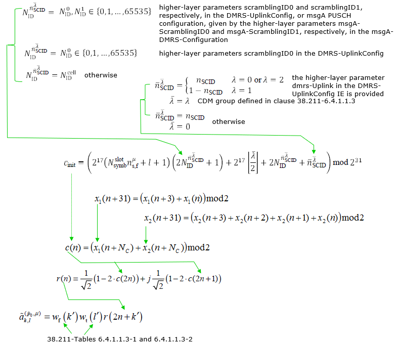
Sequence Generation
< Transform Precoding Not Enabled >
Resource Element Mapping
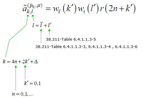
Resource Mapping of PUSCH DMRS is done as following equation. For simplicity, let's think of the location of resource element only (i.e, let's think only of k and l). k represents frequency domain location and l represents time domain location.
With this in mind, the first thing you can notice would be
- Configuration type changes the location pattern in frequency domain
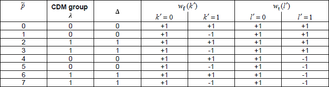
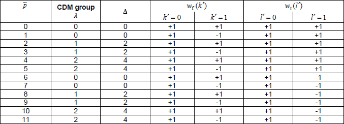
- Configurataion Type 1 : 3 pairs(6 Resource Elements:RE) of DMRS are dispersed in one OFDM symbol/one RB at the interval of 4 REs (4n). The two RE in each pare are apart at the interval of 2 RE(2k'). In short, 6 REs of DMRS symbols are dispersed at every other REs in frequency domain. This supports 8 DMRS ports in case of double-symbol DMRS(port 0~7) and 4 DMRS ports in case of single symbol DMRS(port 1000~1003). See Table 6.4.1.1.3-1 and Table 6.4.1.1.3-2 for further details.
- Configuration Type 2 : 2 pairs(4 Resource Elements:RE) of DMRS are dispersed in one OFDM symbol/one RB at the interval of 6 REs (6n). The two RE in each pare are apart at the interval of 1 RE(k'), meaning that the two REs in each pair are contiguous. This supports 12 DMRS ports in case of double-symbol DMRS(port 0~7) and 8 DMRS ports in case of single symbol DMRS(port 0~11). See Table 6.4.1.1.3-1 and Table 6.4.1.1.3-2 for further details for further details.
- PUSCH mapping type changes the location pattern in time domain
- PUSCH Mapping Type A : In this type, the DMRS symbol can start only at symbol 2 or 3 regardless of PUSCH start and length. It implies this cannot be used when PUSCH start symbol is greater than 3. This is related to the row 'Type A' in PUSCH SLIV table. This type is used for slot based scheduling.
- PUSCH Mapping Type B : In this type, the DMRS symbol can start at the first PUSCH symbol regardless of PUSCH start. This is related to the row 'Type B' in PUSCH SLIV table. This type is used for mini-slot based scheduling
Another points you would notice would be
- frequency domain location(k) is determined by equation(formula) as shown below
- time domain location(l) is determined by a predefined table and predefined value.
< When Transform Preconding is not enabled >

< When Transform Preconding is enabled >
< Resource Element Mapping after Precoding >
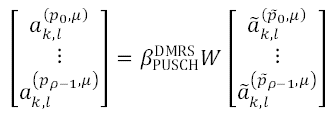
Regardless of whether Transformed Precoding is enabled or not, the DMRS goes through scaling and Precoding procedure as below. W is precoding matrix which is same matrix for PUSCH data. This Procoding step itself is a pretty complicated process and explained in a separate note here.
Tables
Followings are various tables that are used in Sequence Generation and Resource Element Mappaing shown above.
< 38.211 - Table 6.4.1.1.3-1: Parameters for PUSCH DM-RS configuration type 1.>
< 38.211 - Table 6.4.1.1.3-2: Parameters for PUSCH DM-RS configuration type 2. >
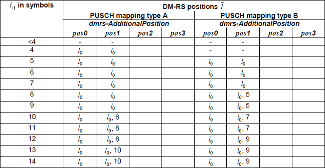
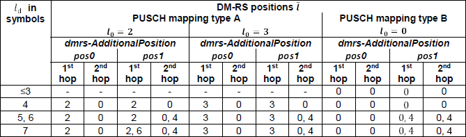
< 38.211 - Table 6.4.1.1.3-3: PUSCH DM-RS positions ![]() within a slot for single-symbol DM-RS and intra-slot frequency hopping disabled.>
within a slot for single-symbol DM-RS and intra-slot frequency hopping disabled.>
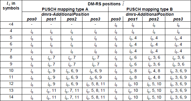
< 38.211 - Table 6.4.1.1.3-4: PUSCH DM-RS positions ![]() within a slot for double-symbol DM-RS and intra-slot frequency hopping disabled. >
within a slot for double-symbol DM-RS and intra-slot frequency hopping disabled. >
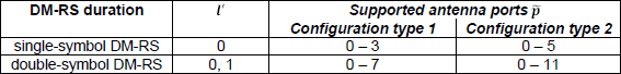
< 38.211 - Table 6.4.1.1.3-5: PUSCH DM-RS time index l' >
< 38.211 - Table 6.4.1.1.3-6: PUSCH DM-RS positions ![]() within a slot for single-symbol DM-RS and intra-slot frequency hopping enabled. >
within a slot for single-symbol DM-RS and intra-slot frequency hopping enabled. >
Reference
[1] Wireless Technology Evolution - Transition from 4G to 5G : 5G Americas