Shell Programming for GPIO
Theoretically, you don't need to use any special programming tool to manipulate each of GPIO pins on the board. All of the GPIO pins are mapped to a specific files(Device Drivers) and you can operate those pins by writing and reading some values to those files mapped to each of the pins. Actually this is one of the most typical Linux concept, saying "In Linux, everything is treated as a file, even hardware like those pins can be a file". To read/write files, you don't need any specific language. You can do it using a couple of commands in the prompt.
The logics explained here can be used in other programming language like C, Python, Java, whatever. Just open the files mapped to each pins and read/write values from/to the files.
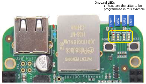
Turning On/Off USR (On Board LED)
As the first example, I will show you how to manipulate the on-board LEDs as shown below. The reason why I picked up these LEDs as the first example is that we don't need to build up any test circuit (No Soldering, No wiring on breadboard ) and the files(drivers) mapped to these LEDs are already created by default in the Linux Kernel on the board (For most of other GPIOs, the files for those pins are not created by default. You have to create those files by a special procedure called 'Export' which will be explained in following section).
At first, you have to find out where the pin map file for usr are located. This location seems to vary depending on Linux kernel version and Beaglebone type. So I had to find out where these files are defined in my board. I did the same trick as follows to find these information.
root@beaglebone:/# cd /
root@beaglebone:/# ls -al -R | grep "leds"
or you may try following
root@beaglebone:/# ls -al -R | grep "usr0"
Then I tried followings... you don't have to do the exact same thing like this.. try as you like
// Flowing command should turn off usr0 LED
root@beaglebone:/# echo 0 > /sys/devices/ocp.3/gpio-leds.8/leds/beaglebone:green:usr0/brightness
// Flowing command should turn off usr1 LED
root@beaglebone:/# echo 0 > /sys/devices/ocp.3/gpio-leds.8/leds/beaglebone:green:usr1/brightness
// Flowing command should turn off usr2 LED
root@beaglebone:/# echo 0 > /sys/devices/ocp.3/gpio-leds.8/leds/beaglebone:green:usr2/brightness
// Flowing command should turn off usr3 LED
root@beaglebone:/# echo 0 > /sys/devices/ocp.3/gpio-leds.8/leds/beaglebone:green:usr3/brightness
// Flowing command should turn on usr0 LED
root@beaglebone:/# echo 1 > /sys/devices/ocp.3/gpio-leds.8/leds/beaglebone:green:usr0/brightness
// Flowing command should turn on usr1 LED
root@beaglebone:/# echo 1 > /sys/devices/ocp.3/gpio-leds.8/leds/beaglebone:green:usr1/brightness
// Flowing command should turn on usr2 LED
root@beaglebone:/# echo 1 > /sys/devices/ocp.3/gpio-leds.8/leds/beaglebone:green:usr2/brightness
// Flowing command should turn on usr3 LED
root@beaglebone:/# echo 1 > /sys/devices/ocp.3/gpio-leds.8/leds/beaglebone:green:usr3/brightness
// By following way, you can figure out the status of a specific usr LED
root@beaglebone:/# cat < /sys/devices/ocp.3/gpio-leds.8/leds/beaglebone:green:usr2/brightness
1 <== This indicates "usr2 is turned on"
Just for your reference, you can get more details on what kind of control you have for each of the usr by looking into the directory as shown below. I would explain further details of each of these items later. For now, just play as I showed above and get some intuition by practice.
root@beaglebone:/# ls /sys/devices/ocp.3/gpio-leds.8/leds/beaglebone:green:usr0 -al
total 0
drwxr-xr-x 3 root root 0 Jan 1 2000 .
drwxr-xr-x 6 root root 0 Jan 1 2000 ..
-rw-r--r-- 1 root root 4096 Mar 1 22:20 brightness
lrwxrwxrwx 1 root root 0 Mar 1 20:54 device -> ../../../gpio-leds.8
-r--r--r-- 1 root root 4096 Mar 1 20:54 max_brightness
drwxr-xr-x 2 root root 0 Mar 1 20:50 power
lrwxrwxrwx 1 root root 0 Jan 1 2000 subsystem -> ../../../../../class/leds
-rw-r--r-- 1 root root 4096 Mar 1 20:54 trigger
-rw-r--r-- 1 root root 4096 Jan 1 2000 uevent
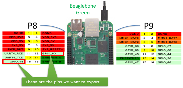
In previous example, you might have noticed how easy it is to control I/O pins using a simple file system. Then you may ask "Can I control all of the IO pins in the same way as shown above ?". I am not sure of pins for serial communication, but at least for all the GPIO the answer is "YES".
However, in default setup you would find the files(drivers) mapped to only a few GPIO pins and couldn't find files for most of other GPIOs. This is because the files(drivers) for the most of the pins are not registered (exported) as a driver file by default. You need to create files for each GPIO pins as you need. In this section, I will show you how to register(expose) those files and control a GPIO pins that you like. I picked two pins as marked below. If you are using Beaglebone Green from Seeedcom, be careful about the direction of the board when you identify the GPIO pins. Based on my test, the direction seems to be different from the document from 192.168.7.2 page.
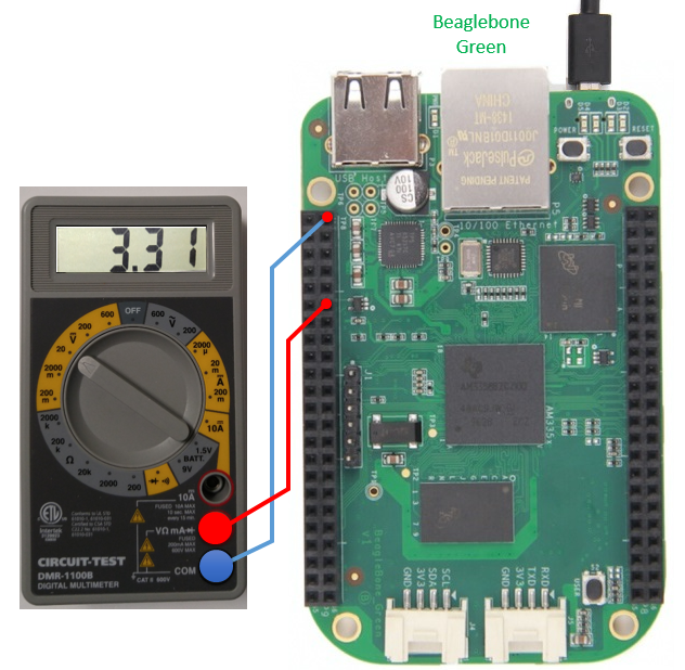
Instead of building a circuit by soldering or wiring on breadboard, I decided to use a simple/lazy way to test the pin operation as shown below. I just connected a digital voltmeter to verify On/Off status of the pin as shown below. This is to test GPIO 60 pin.
The first step is to create a set of files that will be mapped to GPIO 60. It is super simple. You can create the whole set of files for the pin with the single command as shown below.
root@beaglebone:~# echo 60 > /sys/class/gpio/export
I will show you details of what has happened by the command above later. For now, Let's move on to next step right away. Once you export (create) the file, you can determine whether you use the pin as input or output as in the following way. In this example, I set the pin mode to be 'output' as shown below.
root@beaglebone:~# echo out > /sys/class/gpio/gpio60/direction
Now the only thing you need to do is just write value to the file named 'value'. Try writing 1 to the file as show below.
root@beaglebone:~# echo 1 > /sys/class/gpio/gpio60/value
If you read the value on Voltmeter, you would read the value around 3.3 Volt.
Then keep trying followings one by one and check the value on Voltmeter. Did you get what you expected ?
root@beaglebone:~# echo 0 > /sys/class/gpio/gpio60/value
root@beaglebone:~# echo 1 > /sys/class/gpio/gpio60/value
root@beaglebone:~# echo 0 > /sys/class/gpio/gpio60/value
root@beaglebone:~# echo 1 > /sys/class/gpio/gpio60/value
root@beaglebone:~# echo 0 > /sys/class/gpio/gpio60/value
Now let's think in more detail on what's happening when you first tried echo 60 > /sys/class/gpio/export.
First, look into the contents of the following folder before you export the pin. you will get the files as shown below. These are the ones that comes with the board by default.
root@beaglebone:~# ls /sys/class/gpio -al
total 0
drwxr-xr-x 2 root root 0 Jan 1 2000 .
drwxr-xr-x 59 root root 0 Jan 1 2000 ..
--w------- 1 root root 4096 Jan 1 2000 export
lrwxrwxrwx 1 root root 0 Jan 1 2000 gpiochip0 -> ../../devices/virtual/gpio/gpiochip0
lrwxrwxrwx 1 root root 0 Jan 1 2000 gpiochip32 -> ../../devices/virtual/gpio/gpiochip32
lrwxrwxrwx 1 root root 0 Jan 1 2000 gpiochip64 -> ../../devices/virtual/gpio/gpiochip64
lrwxrwxrwx 1 root root 0 Jan 1 2000 gpiochip96 -> ../../devices/virtual/gpio/gpiochip96
--w------- 1 root root 4096 Jan 1 2000 unexport
Now you export GPIO_60 as follows
root@beaglebone:~# echo 60 > /sys/class/gpio/export
Then look into the folder again and you will find a new file (directory) named gpio60 is created as shown below.
root@beaglebone:~# ls /sys/class/gpio -al
total 0
drwxr-xr-x 2 root root 0 Jan 1 2000 .
drwxr-xr-x 59 root root 0 Jan 1 2000 ..
--w------- 1 root root 4096 Mar 1 20:53 export
lrwxrwxrwx 1 root root 0 Mar 1 20:53 gpio60 -> ../../devices/virtual/gpio/gpio60
lrwxrwxrwx 1 root root 0 Jan 1 2000 gpiochip0 -> ../../devices/virtual/gpio/gpiochip0
lrwxrwxrwx 1 root root 0 Jan 1 2000 gpiochip32 -> ../../devices/virtual/gpio/gpiochip32
lrwxrwxrwx 1 root root 0 Jan 1 2000 gpiochip64 -> ../../devices/virtual/gpio/gpiochip64
lrwxrwxrwx 1 root root 0 Jan 1 2000 gpiochip96 -> ../../devices/virtual/gpio/gpiochip96
--w------- 1 root root 4096 Jan 1 2000 unexport
Now look into the gpio60 directory and see what kind of files are created there.
root@beaglebone:~# ls /sys/devices/virtual/gpio/gpio60 -al
total 0
drwxr-xr-x 3 root root 0 Mar 1 20:53 .
drwxr-xr-x 7 root root 0 Jan 1 2000 ..
-rw-r--r-- 1 root root 4096 Mar 1 20:54 active_low
-rw-r--r-- 1 root root 4096 Mar 1 20:54 direction
-rw-r--r-- 1 root root 4096 Mar 1 20:54 edge
drwxr-xr-x 2 root root 0 Mar 1 20:54 power
lrwxrwxrwx 1 root root 0 Mar 1 20:53 subsystem -> ../../../../class/gpio
-rw-r--r-- 1 root root 4096 Mar 1 20:53 uevent
-rw-r--r-- 1 root root 4096 Mar 1 20:54 value
Now try the same thing for GPIO 48 pin. First, connect the Voltmeter as shown below.
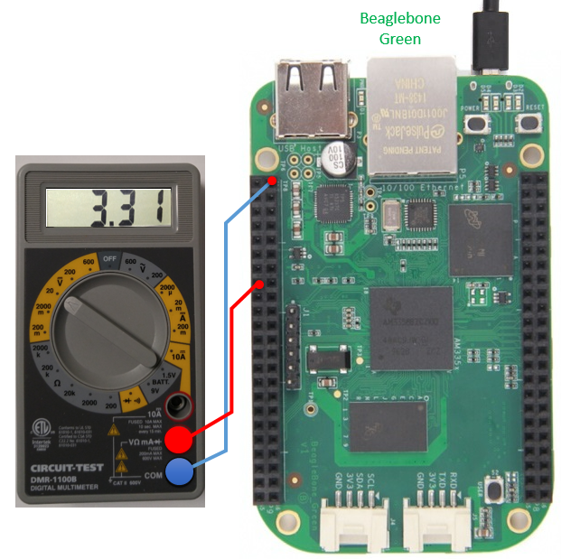
Now try the same thing as you did above. I think you would understand what these lines do without any further explanation.
root@beaglebone:~# echo 48 > /sys/class/gpio/export
root@beaglebone:~# echo out > /sys/class/gpio/gpio48/direction
root@beaglebone:~# echo 1 > /sys/class/gpio/gpio48/value
root@beaglebone:~# echo 0 > /sys/class/gpio/gpio48/value
root@beaglebone:~# echo 1 > /sys/class/gpio/gpio48/value
root@beaglebone:~# echo 0 > /sys/class/gpio/gpio48/value
root@beaglebone:~# echo 1 > /sys/class/gpio/gpio48/value
root@beaglebone:~# echo 0 > /sys/class/gpio/gpio48/value