NOTE : At high level view, it would not be difficult to understand overall concept of CSI. However, getting deeper into the details.. it would become much complicated .. and tooooooooooooo confusing (at least very confusing to me). That is one of the reason why I wrote multiple pages for the same topic (CSI). Multiple pages for the same topic can be additional confusion to some readers (even to me). However, I thought the page would get too big for download if I put everything in single page and I also thought it would not be bad to provide a little bit different aspect for the same topic with multiple post. But as I add more pages (post), I thought it would be good to write a page to provide high level view and help readers combine all those multiple pages that I wrote. Refer to CSI Overview page if you are not familiar with big picture of the CSI report.
Aperiodic CSI arrives only when the network asks for it. The request is a CSI request field of one to five bits, carried inside an uplink grant. A field that small cannot name a cell, a CSI process or a CSI-RS resource. Something else has to name them in advance, and this page follows the field back to it.
- Configuration of the Aperiodic Trigger
- What the Triggered Report Covers
- CSI Request Field Tables in 36.213
- Influence of other MAC activities on CSI report
- Procedure of Aperiodic CSI Report
- Get the Test Procedure and Log / Amarisoft TechAcademy
- Reference
Configuration of the Aperiodic Trigger
The configuration of an aperiodic report is split across two messages, and neither one is readable on its own. The RRC message carries the lists, and the uplink grant carries a small index into them. Reading a live trigger therefore means holding both of them in view at once.
In most case, you would need more information for anything 'Aperiodic' implying 'irregular'. If something is periodic or regular, you may set a certain rule (like a mathematical formula) and pass a couple of parameters to the formula. But in case of Aperiodic, usually it would take more information to configure the behavior since it cannot be easily defined by a fixed rule (e.g, mathematical formula). Especially with the introduction of Carrier Aggregation and the number of Carrier gets larger, the amount of necessary information (e.g, when to send CSI, for which carrier it send CSI) gets larger.
In short, Aperiodic report is configured by two factors : one portion is configured in RRC message and the other portion is configured by DCI. The portion configured by RRC message is described in CQI/RI Feedback type page and the portion configured by DCI is described below in this page.
I assume that you have read through RRC portions of Aperiodic CQI configuration. Now let's look into DCI part of the configuration. The DCI can carry very short contents and it does not have enough space to carry all of those information.
Then, what would be the solution for this ?
The answer is a common old trick. They configure a complicated part in RRC message and lower layer (i.e, DCI in this case) just select a specific configuration defined in RRC message.
Now let's look into the details. The Aperidic CQI/CSI gets configured in RRC message as shown below. At the first glance, you would immediately have questions as below.
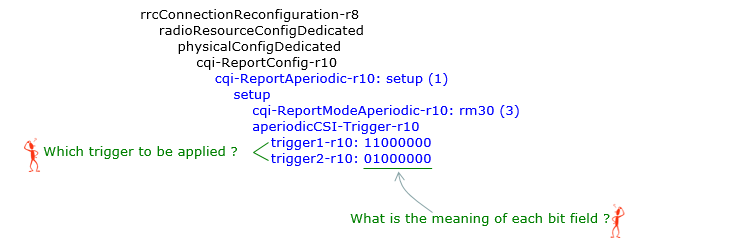
The two questions in the picture are the whole of the problem. One asks which of the bit strings the grant selects. The other asks what a single bit inside a string means.
The tree is one branch of cqi-ReportConfig-r10 : cqi-ReportAperiodic-r10 is set up, and everything below it hangs off that one field.Only two things are configured under it : the reporting mode, printed here as rm30, and the trigger.The trigger is a pair rather than a value : trigger1-r10 and trigger2-r10 sit side by side under aperiodicCSI-Trigger-r10.Each string is eight bits wide : 11000000 and 01000000 in this screenshot, written with the leftmost bit first.The first question has no answer inside the message : the RRC tree does not say which of the two strings applies. That is what sends the reader to the DCI.The second question has no answer there either : a bit is set for a cell. The string does not say which cell that is.
If you can answer these two questions, you already have overall mechanism of Aperiodic CSI report. The answers are as shown below.
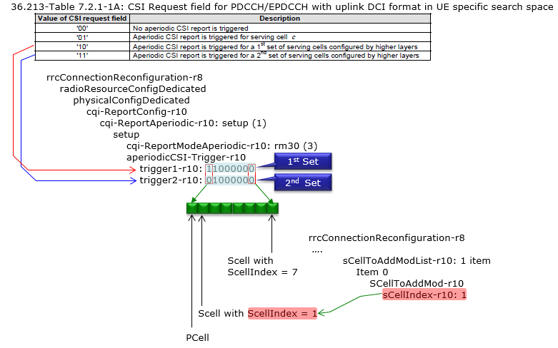
Both answers sit on one picture. The table at the top decides which string the grant reaches. The strip of eight boxes at the bottom decides which cell a bit inside that string stands for.
The table at the top is 36.213 Table 7.2.1-1A : four rows, one for each value of a two bit CSI request field.The value 00 triggers nothing : the grant carries no CSI request at all.The value 01 names serving cell c : that row mentions no set, so neither bit string takes part in it.The value 10 selects the 1st set and 11 the 2nd : the red arrow runs to trigger1-r10 and the blue arrow to trigger2-r10.1st Set and 2nd Set are labels the picture adds : the RRC field names carry no such words. The mapping is the one 36.331 states in prose.The strip below is divided into eight boxes : one per bit of the string, with bit 0 at the left end.Bit 0 stands for the PCell : the leftmost arrow under the strip points at it.Bit 1 stands for the SCell whose sCellIndex is 1 : the pink highlight ties it to sCellIndex-r10: 1 in the sCellToAddModList on the right.Bit 7 stands for the SCell whose sCellIndex is 7 : so the bit position is the ServCellIndex and nothing else.
aperiodicCSI-Trigger in 36.331
The wording below is the normative version of what the picture above draws. Two details in it are worth attention. A bit position is a ServCellIndex rather than an ordinal, and no more than five bits may be set at once.
Formal definition of aperiodicCSI-Trigger is defined in 36.331 as below.
36.331- aperiodicCSI-Trigger
Indicates for which serving cell(s) the aperiodic CSI report is triggered when one or more SCells are configured.
trigger1 corresponds to the CSI request field 10 and trigger2 corresponds to the CSI request field 11, see TS 36.213 table 7.2.1-1A. The leftmost bit, bit 0 in the bit string corresponds to the cell with ServCellIndex=0 and bit 1 in the bit string corresponds to the cell with ServCellIndex=1 etc. Each bit has either value 0 (means no aperiodic CSI report is triggered) or value 1 (means the aperiodic CSI report is triggered). At most 5 bits can be set to value 1 in the bit string. E-UTRAN configures value 1 only for cells configured with transmissionMode set in range tm1 to tm9. One value applies for all serving cells configured with transmissionMode set in range tm1 to tm9 (the associated functionality is common i.e. not performed independently for each cell).
NOTE : Regarding how each of these format are utilized and configured in signaling, check out this tutorial of Amarisoft TechAcademy.
The wording quoted above is the pre Release 13 version of that field description. The current one adds the r13 triggers and raises the limit on how many bits may be set. The description is also only half of what 36.331 says about the trigger. The other half is the type definition. It answers a question the description leaves open: how many bit strings exist, and how wide each one is. The listing below is the current one.
Following is based on
CQI-ReportAperiodic-r10 ::=          CHOICE {
    release                             NULL,
    setup                               SEQUENCE {
        cqi-ReportModeAperiodic-r10         CQI-ReportModeAperiodic,
        aperiodicCSI-Trigger-r10            SEQUENCE {
            trigger1-r10                        BIT STRING (SIZE (8)),
            trigger2-r10                        BIT STRING (SIZE (8))
        }                                                               OPTIONAL   -- Need OR
    }
}

CQI-ReportAperiodic-v1250 ::=        CHOICE {
    release                             NULL,
    setup                               SEQUENCE {
        aperiodicCSI-Trigger-v1250          SEQUENCE {
            trigger-SubframeSetIndicator-r12    ENUMERATED {s1, s2},
            trigger1-SubframeSetIndicator-r12   BIT STRING (SIZE (8)),
            trigger2-SubframeSetIndicator-r12   BIT STRING (SIZE (8))
        }
    }
}

CQI-ReportAperiodic-v1310 ::=        CHOICE {
    release                             NULL,
    setup                               SEQUENCE {
        aperiodicCSI-Trigger-v1310          SEQUENCE {
            trigger1-r13                        BIT STRING (SIZE (32)),
            trigger2-r13                        BIT STRING (SIZE (32)),
            trigger3-r13                        BIT STRING (SIZE (32)),
            trigger4-r13                        BIT STRING (SIZE (32)),
            trigger5-r13                        BIT STRING (SIZE (32)),
            trigger6-r13                        BIT STRING (SIZE (32))
        }                                                               OPTIONAL,  -- Need ON
        aperiodicCSI-Trigger2-r13           CHOICE {
            release                             NULL,
            setup                               SEQUENCE {
                trigger1-SubframeSetIndicator-r13   BIT STRING (SIZE (32)),
                trigger2-SubframeSetIndicator-r13   BIT STRING (SIZE (32)),
                trigger3-SubframeSetIndicator-r13   BIT STRING (SIZE (32)),
                trigger4-SubframeSetIndicator-r13   BIT STRING (SIZE (32)),
                trigger5-SubframeSetIndicator-r13   BIT STRING (SIZE (32)),
                trigger6-SubframeSetIndicator-r13   BIT STRING (SIZE (32))
            }
        }                                                               OPTIONAL   -- Need ON
    }
}

CQI-ReportModeAperiodic ::=          ENUMERATED {
    rm12, rm20, rm22, rm30, rm31,
    rm32-v1250, rm10-v1310, rm11-v1310
}
Every trigger is a BIT STRING rather than a list of cells : the position of a bit carries the meaning. So the width of the string sets how many cells it can reach.Release 10 gives two strings of eight bits : trigger1-r10 and trigger2-r10. That is what the capture and all four examples on this page use.The whole group is OPTIONAL : a UE can be configured for aperiodic reporting with no trigger list. The field values that select a set then have nothing to point at.Release 12 adds a parallel pair of the same width : trigger1-SubframeSetIndicator-r12 and trigger2-SubframeSetIndicator-r12 choose a CSI subframe set instead of a cell. Their ENUMERATED companion offers s1 or s2.Release 13 widens the string to 32 bits and raises the count to six : trigger1-r13 through trigger6-r13, with at most 32 bits set rather than five.Six triggers need three bits in the grant : 36.331 maps trigger1-r13 to the field value 010 and continues in order to trigger6-r13 at 111. That is exactly the numbered part of the three bit table in 36.213.The reporting mode is a plain enumeration : rm30 is the fourth name in it. That is why a decoder prints rm30 (3). The field description in 36.331 reads the names as Mode 1-2, Mode 2-0, Mode 2-2 and so on, so rm30 is Mode 3-0.
Example 1
The first case is the one that looks broken and is not. Both bit strings are all zeros, so the two field values that select a set have no cell to select. One of the four values still produces a report, and the table below shows which.
Assumption : Carrier Aggregation is configured
Assumption : the CSI request arrives in an uplink grant for the P Cell
|
Trigger in RRC Message |
CSI Field |
P Cell |
S Cell1 |
|
trigger1 = 00000000 trigger2 = 00000000 |
00 |
No Report |
No Report |
|
01 |
Report |
No Report |
|
|
10 |
No Report |
No Report |
|
|
11 |
No Report |
No Report |
The 00 row needs no configuration at all : the value means that no aperiodic report is triggered, whatever the bit strings hold.The 10 and 11 rows are empty because the strings are : trigger1 reaches no cell and neither does trigger2, so both values pass without a report.The 01 row does not come from the trigger at all : 36.331 ties trigger1 to the field value 10 and trigger2 to the value 11. Neither of them is tied to 01.36.213 Table 7.2.1-1A answers that row instead : it scopes the report to serving cell c rather than to a configured set.Serving cell c is the cell the uplink grant is for : clause 7.2.1 has the UE report on serving cell c after decoding an uplink DCI format for that same cell. The grant decides it, and the bit strings do not.That is why the S Cell1 column reads No Report on the 01 row : the grant assumed here is for the P Cell. The P Cell is therefore serving cell c.
Example 2
The second case sets a single bit, and it sets it in the first string only. Bit 0 stands for ServCellIndex 0, which is the PCell. The field value that reaches that string is 10, so that value now has exactly one cell behind it.
Assumption : Carrier Aggregation is configured
Assumption : the CSI request arrives in an uplink grant for the P Cell
|
Trigger in RRC Message |
CSI Field |
P Cell |
S Cell1 |
|
trigger1 = 10000000 trigger2 = 00000000 |
00 |
No Report |
No Report |
|
01 |
Report |
No Report |
|
|
10 |
Report |
No Report |
|
|
11 |
No Report |
No Report |
Only the 10 row changes from the first case : it now reaches the PCell, because bit 0 of trigger1 is set.The SCell stays silent on that row : bit 1 is zero, so the set selected by 10 has one member.
Example 3
The third case widens the same string by one bit. Bit 1 stands for ServCellIndex 1, which is the SCell in this configuration. One field value now triggers two cells at once, and that is what a set of serving cells means.
Assumption : Carrier Aggregation is configured
Assumption : the CSI request arrives in an uplink grant for the P Cell
|
Trigger in RRC Message |
CSI Field |
P Cell |
S Cell1 |
|
trigger1 = 11000000 trigger2 = 00000000 |
00 |
No Report |
No Report |
|
01 |
Report |
No Report |
|
|
10 |
Report |
Report |
|
|
11 |
No Report |
No Report |
One field value now triggers two cells : bits 0 and 1 of trigger1 are both set. So the value 10 reports on the PCell and the SCell together.The second string is still unused : the 11 row therefore behaves exactly as it did in the first case.
Example 4
The fourth case is the first to use both strings. Each one is read independently. So the two field values no longer overlap. The second string here holds a cell that the first string does not. That is the arrangement a scheduler uses to ask for one cell without the other.
Assumption : Carrier Aggregation is configured
Assumption : the CSI request arrives in an uplink grant for the P Cell
|
Trigger in RRC Message |
CSI Field |
P Cell |
S Cell1 |
|
trigger1 = 11000000 trigger2 = 01000000 |
00 |
No Report |
No Report |
|
01 |
Report |
No Report |
|
|
10 |
Report |
Report |
|
|
11 |
No Report |
Report |
The two strings are read independently : trigger1 holds bits 0 and 1, trigger2 holds bit 1 alone. No rule ties the second to the first.The 11 row reaches the SCell without the PCell : bit 0 of trigger2 is zero. That is the arrangement a scheduler uses to ask one cell for CSI on its own.Two values now cover three different answers : both cells on 10, the SCell alone on 11, and the P Cell alone on 01.
The four tables vary one thing at a time. The first sets no bits, the second sets one, the third sets two in the same string. The fourth spreads them across both strings. Every row of every table follows from the same two rules.
A bit position is a ServCellIndex : bit 0 is the PCell, bit 1 is the SCell whose sCellIndex is 1, and so on to bit 7.A string belongs to one field value : trigger1 to the value 10 and trigger2 to the value 11.The 01 row never depends on either string : it is scoped to serving cell c. That is why it reads the same in all four tables, whatever the bits hold.Carrier Aggregation is what makes the strings necessary : with one serving cell there is nothing to choose between. The assumption printed above each table says so.
What the Triggered Report Covers
Knowing which cells report is not the whole answer. A single cell can carry several CSI processes, several eMIMO types and several CSI-RS resources. No bit in the trigger distinguishes them. The table below sorts that question into six cases, and the table after it says what each case reports on.
|
CSI request bit length |
1 |
|
|
1 |
|
|
|
|
|
|
Transmission Mode |
1-9 |
|
|
10 |
|
|
|
|
|
|
|
csi-SubframePatternConfig-r12 |
X |
|
|
X |
|
|
|
|
|
|
|
eMIMO-Type2 |
|
O |
|
|
O |
|
|
|
|
|
|
csi-RS-ConfigNZP-ApList |
|
|
O |
|
|
O |
|
|
|
|
|
numberActivatedAperiodicCSI-RS-Resources |
|
|
1 |
|
|
1 |
|
|
|
|
|
Table 7.2.1 |
|
|
|
1B |
1B |
|
|
|
|
|
|
Bit value in Table 7.2.1 |
|
|
|
'01' |
'01' |
|
|
|
|
|
|
The report triggered for |
#1 |
#2 |
#3 |
#4 |
#5 |
#6 |
|
|
|
|
Read the table down a column rather than across a row : each column is one case. The row labels are the conditions that define it.The left three columns are transmission modes 1 to 9 : the Transmission Mode row prints 1-9 in the first of them.The right three columns are transmission mode 10 : the same row prints 10 in the fourth column. 36.331 tells the UE to ignore cqi-ReportModeAperiodic when that mode is configured.Each group of three adds one condition at a time : the plain case first, then eMIMO-Type2, then csi-RS-ConfigNZP-ApList with numberActivatedAperiodicCSI-RS-Resources set to 1.The bottom row is the answer : it points at one of the six statements listed below the table.The table is drawn eleven columns wide and six are filled : the five empty columns on the right are room left for more cases, not cases with no answer.
The bottom row of the table above points into the list below. Each entry finishes the sentence that begins when the CSI request field triggers a report. So the six of them are the six things a triggered report can be about.
|
|
|
|
#1 |
a report is triggered for serving cell c |
|
#2 |
a report is for a higher layer configured eMIMO type of the aperiodic CSI configured for the UE on the serving cell c |
|
#3 |
the report is for the activated CSI-RS resource for the serving cell c . |
|
#4 |
a report is triggered for a set of CSI process(es) for serving cell c |
|
#5 |
the report is for a higher layer configured eMIMO type |
|
#6 |
the report is for the activated CSI-RS resource for the CSI process. |
|
|
|
|
|
#1 and #4 differ only in what is counted : one names the serving cell, the other names a set of CSI processes for that serving cell.#2 and #5 both name a higher layer configured eMIMO type : #2 ties it to the aperiodic CSI configured on the serving cell. #5 leaves it at the eMIMO type.#3 and #6 both name the activated CSI-RS resource : #3 for the serving cell and #6 for the CSI process.The two halves run in the same order : cell, then eMIMO type, then CSI-RS resource. That is why the table above has three columns on each side.None of these six is carried in the grant : every condition in the table above is an RRC setting. The CSI request field only starts the report.
CSI Request Field Tables in 36.213
One CSI request field has eleven tables behind it, and reading the wrong one makes every code point wrong. The eleven differ in two ways only: how wide the field is, and what a set is made of. Picking the right one is a short procedure, and it runs before the tables are any use at all.
Which Table Applies
Three questions settle it, and the first settles most of it. How many bits does the CSI request field hold? Is any serving cell configured with a CSI subframe pattern? The third question depends on the width, and at four and five bits there is none.
Clause 7.2.1 states the answer as fourteen separate rules. The table below is those fourteen rules as fourteen rows. Read down the first column to the width of the field, then across.
CSI request field |
csi-SubframePatternConfig-r12 |
Third condition |
Table to read |
1 bit |
not configured on any serving cell |
transmission mode 1 to 9 |
none : the report is for serving cell c |
not configured on any serving cell |
transmission mode 10 |
the '01' row of 7.2.1-1B |
|
configured on at least one serving cell |
no further condition |
the '01' row of 7.2.1-1C |
|
2 bits |
not configured on any serving cell |
every serving cell in transmission mode 1 to 9 |
7.2.1-1A |
not configured on any serving cell |
at least one serving cell in transmission mode 10 |
7.2.1-1B |
|
configured on at least one serving cell |
no further condition |
7.2.1-1C |
|
3 bits |
not configured on any serving cell |
no csi-RS-ConfigNZP-ApList, or one activated aperiodic CSI-RS resource for each CSI process |
7.2.1-1D |
configured on at least one serving cell |
the same condition |
7.2.1-1E |
|
not configured on any serving cell |
more than one activated aperiodic CSI-RS resource for at least one CSI process |
7.2.1-1F |
|
configured on at least one serving cell |
the same condition |
7.2.1-1G |
|
4 bits |
not configured on any serving cell |
no further condition |
7.2.1-1H |
configured on at least one serving cell |
no further condition |
7.2.1-1I |
|
5 bits |
not configured on any serving cell |
no further condition |
7.2.1-1J |
configured on at least one serving cell |
no further condition |
7.2.1-1K |
The pairing question is always the same one : csi-SubframePatternConfig-r12 on any serving cell picks the second table of a pair, and its absence picks the first.Transmission mode only matters at one and two bits : transmission mode 10 on a serving cell moves the reader from 7.2.1-1A to 7.2.1-1B. From three bits upward every table already counts CSI processes.A cell in transmission mode 1 to 9 still fits a CSI process table : there the CSI process means the aperiodic CSI configured on that serving cell. Clause 7.2.1 says so for 7.2.1-1B to 7.2.1-1E.The aperiodic CSI-RS question only matters at three bits : more than one activated resource for a CSI process moves the reader from 7.2.1-1D to 7.2.1-1F.Four and five bits need no third question : the width already implies the aperiodic CSI-RS case, so only the subframe pattern is left to ask about.A one bit field has no table of its own : clause 7.2.1 sends it to the '01' row of 7.2.1-1B or 7.2.1-1C. In transmission modes 1 to 9 with no subframe pattern it reads no table at all.That last case is the one drawn in the section above : the six column matrix there is the one bit field. That is why its rows read Table 7.2.1 of 1B and a bit value of '01'.
The width is not in 36.213 at all. It is set by the DCI format description in 36.212 clause 5.3.3.1.1, so it is the one input a reader has to fetch from another document. Two things decide it : how many downlink cells the UE has, and how many aperiodic CSI-RS resources are activated. DCI format 0 and DCI format 4 both carry the field.
Activated aperiodic CSI-RS resources |
UE configuration |
CSI request field |
none, or one for each CSI process |
more than five downlink cells |
3 bits |
up to five downlink cells, and one of : more than one downlink cell, more than one CSI process, two CSI measurement sets set by csi-MeasSubframeSet |
2 bits |
|
anything else |
1 bit |
|
more than one for at least one CSI process |
more than five downlink cells |
5 bits |
up to five downlink cells, and one of : more than one downlink cell, more than one CSI process, two CSI measurement sets set by csi-MeasSubframeSet |
4 bits |
|
anything else |
3 bits |
The lower half is the upper half plus two bits : 1, 2 and 3 become 3, 4 and 5. The shift happens as soon as one CSI process has more than one activated aperiodic CSI-RS resource.More than five downlink cells reaches the widest field on its own : no other condition is needed for the 3 bit or the 5 bit case.The middle width needs one of three things : more than one downlink cell, more than one CSI process, or two CSI measurement sets configured with csi-MeasSubframeSet.Every width above the narrowest needs the UE specific search space : 36.212 allows them only for a DCI mapped onto the search space given by the C-RNTI. The heading of all eleven tables says the same thing.The two specifications spell one parameter differently : 36.212 writes CSI-RS-ConfigNZPAperiodic where 36.213 and 36.331 write csi-RS-ConfigNZP-ApList. The condition either side of the name is word for word the same.
The capture in the last section can be run through both tables, as far as the excerpt allows. It adds one SCell beside the PCell, so the UE has two downlink cells and no more than five. Nothing in it configures csi-SubframePatternConfig-r12 or an aperiodic CSI-RS list. That gives a two bit CSI request field. The only transmission mode the excerpt prints is tm1. A two bit field with no subframe pattern and no cell in mode 10 lands on Table 7.2.1-1A. That is the table this page has been reading all along.
The Eleven Tables
The screenshots below are the tables themselves, in the order clause 7.2.1 lists them. Each one carries a version stamp of its own, and each still matches v19.4.0 in its width and in its heading.
Followings are tables from 36.213 v17.5 - 7.2.1
< Table 7.2.1-1A: CSI Request field for PDCCH/EPDCCH/SPDCCH with uplink DCI format in UE specific search space >

The only table in the run whose sets are serving cells. Every other table counts CSI processes or CSI-RS resources instead.
< Table 7.2.1-1B: CSI Request field for PDCCH/EPDCCH/SPDCCH with uplink DCI format in UE specific search space >

The same two bit field, with CSI processes in the place of serving cells.
< Table 7.2.1-1C: CSI Request field for PDCCH/EPDCCH/MPDCCH/SPDCCH with uplink DCI format in UE specific search space >
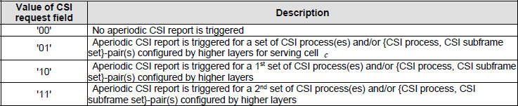
Table 7.2.1-1B with the CSI subframe set variant added. Its heading is also the only one in the run that names MPDCCH.
< Table 7.2.1-1D: CSI Request field for PDCCH/EPDCCH/SPDCCH with uplink DCI format in UE specific search space >
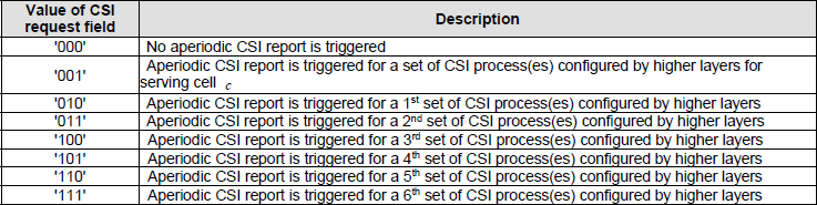
Three bits instead of two, so six numbered sets follow the serving cell row rather than two.
< Table 7.2.1-1E: CSI Request field for PDCCH/EPDCCH/SPDCCH with uplink DCI format in UE specific search space >
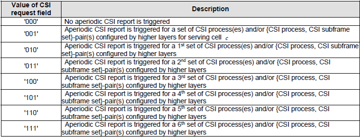
Table 7.2.1-1D with the CSI subframe set variant added.
< Table 7.2.1-1F: CSI Request field for PDCCH/EPDCCH/SPDCCH with uplink DCI format in UE specific search space >
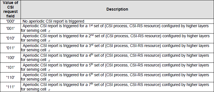
The exception in the run. Every triggering row here is a numbered set, and every one of them is scoped to serving cell c.
< Table 7.2.1-1G: CSI Request field for PDCCH/EPDCCH/SPDCCH with uplink DCI format in UE specific search space >
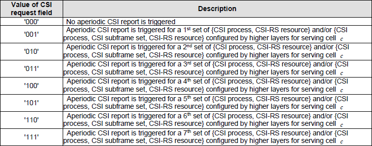
Table 7.2.1-1F with the CSI subframe set variant added.
< Table 7.2.1-1H: CSI Request field for PDCCH/EPDCCH with uplink DCI format in UE specific search space>
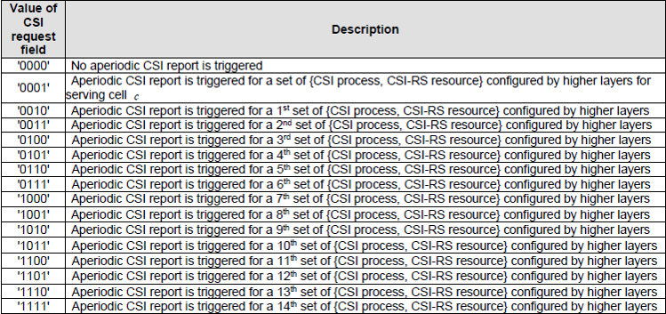
Four bits, so fourteen numbered sets follow the serving cell row.
< Table 7.2.1-1I: CSI Request field for PDCCH/EPDCCH with uplink DCI format in UE specific search space>
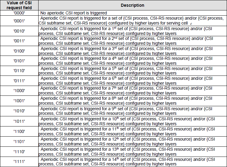
Table 7.2.1-1H with the CSI subframe set variant added.
< Table 7.2.1-1J: CSI Request field for PDCCH/EPDCCH with uplink DCI format in UE specific search space >
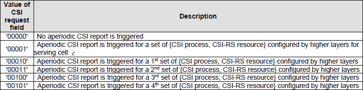
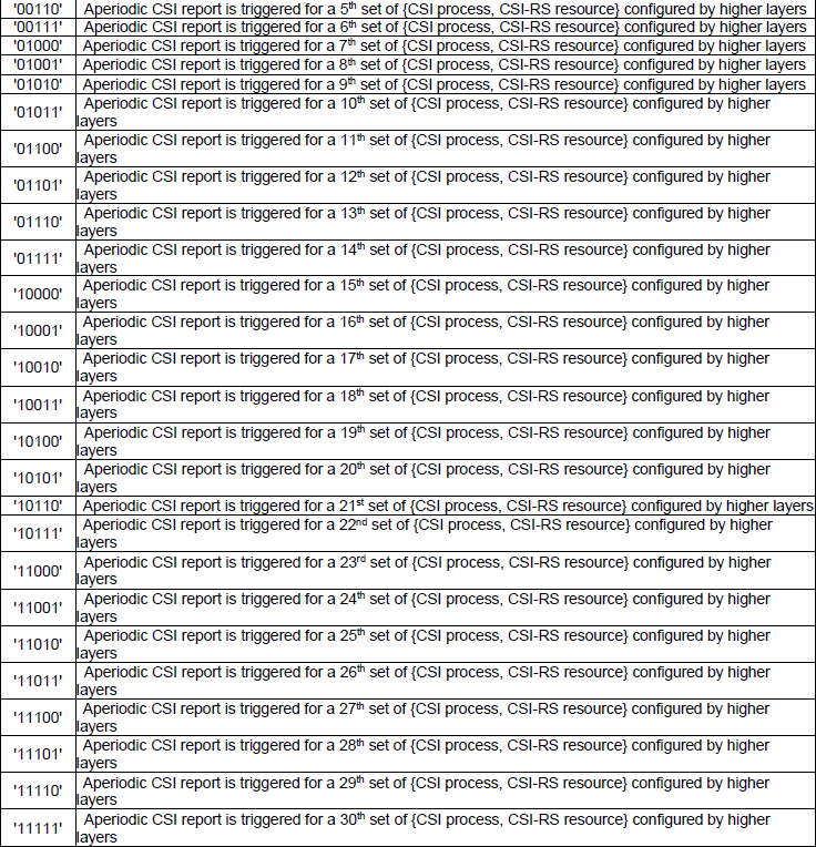
Five bits, so thirty numbered sets. The table is long enough that the screenshot is split in two.
< Table 7.2.1-1K: CSI Request field for PDCCH/EPDCCH with uplink DCI format in UE specific search space >
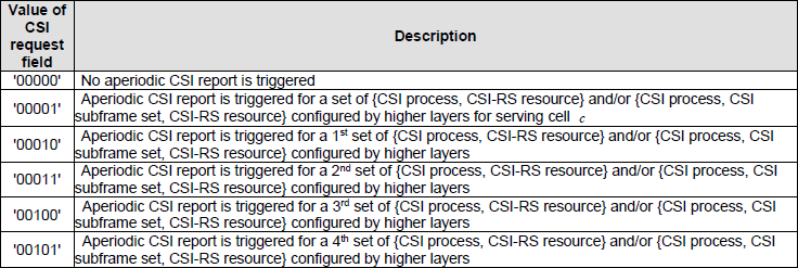
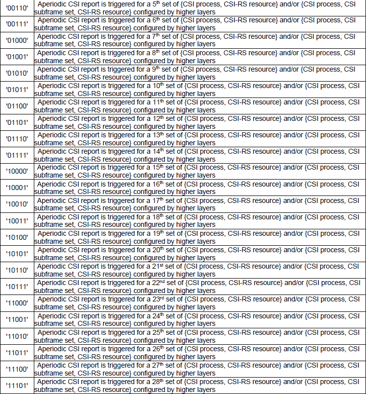

Table 7.2.1-1J with the CSI subframe set variant added, split across three screenshots.
The eleven fit on one page when only their differences are kept. The count in the third column is the number of numbered sets. That is every triggering row except the one scoped to serving cell c.
Table |
Field width |
Numbered sets |
What a set is made of |
7.2.1-1A |
2 bits |
2 |
serving cells |
7.2.1-1B |
2 bits |
2 |
CSI processes |
7.2.1-1C |
2 bits |
2 |
CSI processes, and {CSI process, CSI subframe set} pairs |
7.2.1-1D |
3 bits |
6 |
CSI processes |
7.2.1-1E |
3 bits |
6 |
CSI processes, and {CSI process, CSI subframe set} pairs |
7.2.1-1F |
3 bits |
7 |
{CSI process, CSI-RS resource} pairs, every row for serving cell c |
7.2.1-1G |
3 bits |
7 |
the same, with {CSI process, CSI subframe set, CSI-RS resource} added |
7.2.1-1H |
4 bits |
14 |
{CSI process, CSI-RS resource} pairs |
7.2.1-1I |
4 bits |
14 |
the same, with {CSI process, CSI subframe set, CSI-RS resource} added |
7.2.1-1J |
5 bits |
30 |
{CSI process, CSI-RS resource} pairs |
7.2.1-1K |
5 bits |
30 |
the same, with {CSI process, CSI subframe set, CSI-RS resource} added |
Every one of the eleven reserves the all zero code point : 00, 000, 0000 and 00000 all read that no aperiodic CSI report is triggered.In 7.2.1-1A to 7.2.1-1E the second row is scoped to serving cell c : the numbered sets start on the row below it.7.2.1-1F and 7.2.1-1G break that pattern : there the first triggering row is already the 1st set. Every triggering row carries the words for serving cell c.Ten of the eleven form five pairs : 1B with 1C, 1D with 1E, 1F with 1G, 1H with 1I and 1J with 1K. The second of each pair adds the CSI subframe set wording and changes nothing else.7.2.1-1A has no partner : it is the serving cell table, and a CSI subframe set is a property of a CSI process rather than of a cell.One more bit roughly doubles the sets : 2, then 6 or 7, then 14, then 30, as the field goes from two bits to five.The headings name different carriers of the grant : 1A to 1G say PDCCH, EPDCCH and SPDCCH, 1C adds MPDCCH, and 1H to 1K name PDCCH and EPDCCH only.The 32 bit triggers of Release 13 belong to this table : the six of them fill the numbered rows of the three bit table. That is where a six way choice first needs more than two bits.
Influence of other MAC activities on CSI report
Since there are some other periodic activities, those activities can influence Periodic/Aperidic CSI Report as described in CQI Report and DRX section. CSI report is triggered by DCI, so a certain DCI format can influence CSI Report as described in CQI Report and SR section.
The dependency runs one way. An aperiodic report cannot start itself. So anything that keeps the grant from arriving keeps the report from happening. Nothing is queued for a later subframe.
Two things have to reach the UE before a report can go out. The first is the PDCCH carrying the uplink grant with the CSI request field set. The second is the PUSCH resource that same grant allocates, because clause 7.2.1 of 36.213 is titled Aperiodic CSI Reporting using PUSCH. The periodic case has neither dependency: clause 7.2.2 reports on PUCCH. Its instants are worked out from an index in the RRC message long before the subframe arrives.
DRX therefore affects the two cases differently. A UE in its DRX sleep is not reading PDCCH. So a trigger sent then is simply never seen. The network learns nothing until the next opportunity it creates. A periodic report has no such gap in its planning, although its own instants can still fall where the UE is not transmitting. The CQI Report and DRX section linked above covers the timing.
The two report types also share one uplink and one subframe, so they can be asked for at the same moment. That collision is a scheduling question rather than a configuration one. It is the reason a log often shows fewer reports than the configuration seems to promise.
Aperiodic CSI needs an uplink grant and periodic CSI does not : one is carried on PUSCH and the other on PUCCH.Anything that stops the UE reading PDCCH stops the trigger : the request and the resource travel in the same DCI.A missed aperiodic report is simply absent : no later instant is already scheduled, so the network has to ask again.The configuration outlives the reports : the trigger lists stay valid until the cell set changes. So a quiet log does not mean a missing configuration.
Procedure of Aperiodic CSI Report
Four messages are involved, and only two of them repeat. The first pair sets the trigger lists up and can then be left alone for as long as the cell configuration holds. The second pair is the loop that runs every time the network wants a report.
|
Direction |
Message or DCI |
Comments |
|
UE <-- NW |
RRC Connection Reconfiguration |
NW does not need to send this for every CSI report. It only have to send this when Trigger setting changes |
|
UE --> NW |
RRC Connection Reconfiguration Complete |
|
|
UE <-- NW |
||
|
UE --> NW |
PUSCH with UCI carrying CSI |
The first two rows happen once : the Comments column says the network sends the reconfiguration only when the trigger setting changes.The last two rows are the loop : one DCI Format 0 carrying the CSI request, and one PUSCH carrying the CSI back.The report travels on PUSCH rather than PUCCH : that is the difference from the periodic case, and it is why a grant has to exist first.Nothing in the loop repeats on a timer : the interval between two reports is whatever interval the scheduler chooses.
The capture below is the first row of that table as a real network sent it. It is worth working through, because every field the sections above discussed appears in it at once. The two trigger values are printed in hexadecimal rather than as bits.
RRC Connection Reconfiguration decoded from a live network capture, quoted as the author recorded it. None of its values have been corrected against a specification.
rrcConnectionReconfiguration
    rrc-TransactionIdentifier: 0
    criticalExtensions: c1 (0)
        c1: rrcConnectionReconfiguration-r8 (0)
            rrcConnectionReconfiguration-r8
                radioResourceConfigDedicated
                    physicalConfigDedicated
                        cqi-ReportConfig-r10
                            cqi-ReportAperiodic-r10: setup (1)
                                setup
                                    cqi-ReportModeAperiodic-r10: rm30 (3)
                                    aperiodicCSI-Trigger-r10
                                        trigger1-r10: 80 [bit length 8, 1000 0000 ]
                                        trigger2-r10: c0 [bit length 8, 1100 0000 ]
                            nomPDSCH-RS-EPRE-Offset: 0dB (0)
                        pucch-ConfigDedicated-v1020
                            pucch-Format-r10: channelSelection-r10 (1)
                                channelSelection-r10
                                    n1PUCCH-AN-CS-r10: setup (1)
                                        setup
                                            n1PUCCH-AN-CS-List-r10: 2 items
                                                Item 0
                                                    N1PUCCH-AN-CS-r10: 4 items
                                                        Item 0
                                                            N1PUCCH-AN-CS-r10 item: 361
                                                        Item 1
                                                            N1PUCCH-AN-CS-r10 item: 362
                                                        Item 2
                                                            N1PUCCH-AN-CS-r10 item: 363
                                                        Item 3
                                                            N1PUCCH-AN-CS-r10 item: 364
                                                Item 1
                                                    N1PUCCH-AN-CS-r10: 4 items
                                                        Item 0
                                                            N1PUCCH-AN-CS-r10 item: 365
                                                        Item 1
                                                            N1PUCCH-AN-CS-r10 item: 366
                                                        Item 2
                                                            N1PUCCH-AN-CS-r10 item: 367
                                                        Item 3
                                                            N1PUCCH-AN-CS-r10 item: 368
                nonCriticalExtension
                    nonCriticalExtension
                        nonCriticalExtension
                            sCellToAddModList-r10: 1 item
                                Item 0
                                    SCellToAddMod-r10
                                        sCellIndex-r10: 1
                                        radioResourceConfigDedicatedSCell-r10
                                            physicalConfigDedicatedSCell-r10
                                                nonUL-Configuration-r10
                                                    antennaInfo-r10
                                                        transmissionMode-r10: tm1 (0)
                                                        ue-TransmitAntennaSelection: release (0)
                                                            release: NULL
                                                    pdsch-ConfigDedicated-r10
                                                        p-a: dB0 (4)
                                                ul-Configuration-r10
                                                    cqi-ReportConfigSCell-r10
                                                        cqi-ReportModeAperiodic-r10: rm30 (3)
                                                        nomPDSCH-RS-EPRE-Offset-r10: 0dB (0)
                                                        cqi-ReportPeriodicSCell-r10: release (0)
                                                            release: NULL
trigger1-r10 is 80, which is 1000 0000 : bit 0 alone. So the CSI request value 10 triggers the PCell and nothing else.trigger2-r10 is c0, which is 1100 0000 : bits 0 and 1. So the value 11 triggers the PCell and the SCell together.The decoder prints the bits for you : the bracket after each value carries the length and the expansion. That is the fastest check that a hex value was read correctly.Bit 1 has a cell to point at : sCellToAddModList-r10 carries one item, and its sCellIndex-r10 is 1. Bits 2 to 7 point at nothing in this configuration.Both cells report in the same mode : cqi-ReportModeAperiodic-r10 is rm30 under cqi-ReportConfig-r10 for the PCell. The SCell carries rm30 again under cqi-ReportConfigSCell-r10.The SCell has no periodic reporting at all : cqi-ReportPeriodicSCell-r10 is released, so everything that cell reports is aperiodic.The SCell runs transmissionMode-r10 tm1 : that sits inside the tm1 to tm9 range the field description restricts the trigger bits to.
Putting those together gives the whole behaviour of this UE in four lines. A CSI request of 00 produces no report. A request of 01 produces a report for serving cell c. A request of 10 produces a report for the PCell. A request of 11 produces a report for the PCell and the SCell together.
The four examples above do not include that combination. Example 2 sets the same trigger1 and leaves trigger2 empty. So the two agree on the value 10 and differ on 11. A live network, in other words, uses the second string for the case the examples leave unused.
Reference
The two specifications below are the ones this page works from. The eleven CSI request field tables are screenshots of the first, in the version named above them, and the clause text was read in the version named here. The trigger definitions and the field descriptions come from the second.
- 36.213 : 3GPP - E-UTRA; Physical layer procedures, v19.4.0. Clause 7.2.1 is Aperiodic CSI Reporting using PUSCH, and it holds Table 7.2.1-1A through Table 7.2.1-1K. Its opening paragraphs are where serving cell c is defined.
- 36.331 : 3GPP - E-UTRA; Radio Resource Control (RRC); Protocol specification, v19.3.0. The source of CQI-ReportAperiodic-r10, CQI-ReportAperiodic-v1250, CQI-ReportAperiodic-v1310 and CQI-ReportModeAperiodic, and of the aperiodicCSI-Trigger field description.