|
4G/LTE - Cat M |
||
|
Category M(LTE-M)
Recently (as of Sep 2015) you might have seen two obvious directions of LTE evolution. One direction is 'higher and higher throughput' based on Carrier Aggregation (2 CC, 3CC and even 4CC) and the other direction is 'lower and lower throughput' with 'Low Cost' and 'Lower Energy Consumption'. The second direction (Lower throughput with Low Cost/Energy) is called 'MTC'. MTC has a certain set of criteria to meet (Refer to MTC page for these criteria and technical issues). Probably the first category that might be classified as an MTC device would be Category 1 device. But this Category 1 is just desinged as low performance LTE and not so much optimized to be called as 'efficient MTC' device. Probably the first LTE device that is specifically designed for MTC would be Category 0 device. (Refer to Category 0 page to see why Category 0 is so special). Category M (or LTE-M) is the device that is even more optimized towards even lower power consumption, even simpler complexity leading to even lower device cost. What dose 'M' stands for ? Not sure... probably 'MTC' or 'Minus (lower than Cat 0 -:))
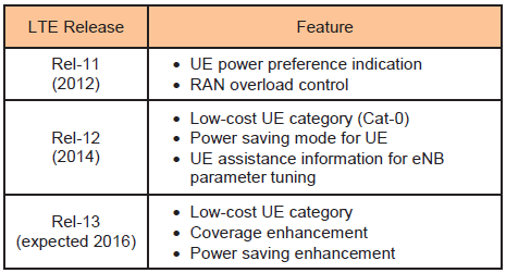
Following table (Reference 1 ) would show you the general trands of the evolution of LTE-M devices .
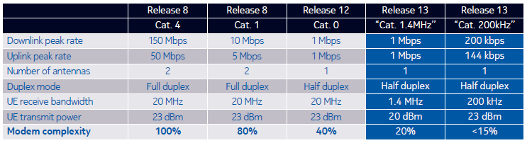
Following table( Reference 2 ) would show you some of key technical charateristics of each LTE based MTC devices in comparison to normal LTE device (Cat 4).
In terms of eNB lower layer point of view, there wouldn't be any modification required until Cat 1 and Cat 0. (In case of Cat 0, there will be some modification required at higher layer protocol like PSM, but it is nothing to do with physical layer in eNB). Most of the modification would be on UE side (overall strategy of those modification is described in MTC page).
However, there should be several modifications on both side (UE and eNB) for Cat 1.4 Mhz or Cat 200 KHz. Some of these modifications are as follows :
In case of 200 Khz (NB Cat M), there should be even more modification in terms of protocol because it is only 1RB and 1 RB System BW has never been tried before in LTE. The overall feature of NB IoT is now outlined in 3GPP RP-151621 as follows.
3 Mode of Operation : 1.‘Stand-alone operation’ utilizing for example the spectrum currently being used by GERAN systems as a replacement of one or more GSM carriers 2.‘Guard band operation’ utilizing the unused resource blocks within a LTE carrier’s guard-band 3.‘In-band operation’ utilizing resource blocks within a normal LTE carrier
Physical Waveform :
Now we have other names which seems to be coined just to confuse us :). Recently (around Feb 2016), I start hearing other names called LTE-M1 and LTE-M2. I haven't seen these names in 3GPP, but LTE-M1 seems to indicate LTE 1.4Mhz and LTE-M2 seems to indicate LTE 200 Khz. I think the 3GPP terms for LTE-M2 is NB-LTE according to TR 45.820 ( Ref [4] )
Reference
[1] Recent Advancements in M2M Communications in 4G Networks and Evolution Towards 5G Rapeepat Ratasuk‡, Athul Prasad†, Zexian Li†, Amitava Ghosh‡, and Mikko A. Uusitalo† ‡Nokia Networks, Arlington Heights, IL, USA. †Nokia Technologies, 00045 Nokia Group, P.O. Box 226, Espoo, Finland.
[2] (Nokia Whitepaper) LTE-M – Optimizing LTE for the Internet of Things
[3] 3GPP RP-151621
[4] 3GPP TR 45.820 V13.1.0 (2015-11) : Cellular system support for ultra-low complexity and low throughput Internet of Things (CIoT) (Release 13)
|
||