A UE cannot tell that it missed a downlink grant. The DAI is the counter that closes that gap, so that the UE and the eNB agree on how many acknowledgements are due. This page builds it from two scheduling examples and one failure.
DAI stands for Downlink Assignment Index. When you say 'Index', it usually means a unique number assigned to each elements in an array or set. It usually is assigned to each element in increasing order.
How DAI is assigned ?
DAI is also a type of index. Then what is the set (or array) to which this index is used for. The set in this case is 'all of the transmitted (scheduled) downlink data(PDSCH) which is bundled to one HARQ ACK/NAC transmission' in TDD operation (If this does not sound clear to you, I would suggest you to read 'HARQ Timing' section first).
One thing is worth settling before the examples. The field is two bits wide, which 36.212 states where it lists the contents of the uplink grant. 36.213 clause 7.3 is where the two bits are given a meaning. The table below is that mapping.
DAI, MSB then LSB |
Value |
Number of serving cells with PDSCH transmission associated with PDCCH, EPDCCH or SPDCCH, and serving cell with PDCCH, EPDCCH or SPDCCH indicating DL SPS release |
0,0 |
1 |
1 or 5 or 9 or 13 or 17 or 21 or 25 or 29 |
0,1 |
2 |
2 or 6 or 10 or 14 or 18 or 22 or 26 or 30 |
1,0 |
3 |
3 or 7 or 11 or 15 or 19 or 23 or 27 or 31 |
1,1 |
4 |
0 or 4 or 8 or 12 or 16 or 20 or 24 or 28 or 32 |
The field is two bits : 36.212 gives the uplink grant a Downlink Assignment Index of 2 bits, defined in clause 7.3 of 36.213.Two bits count to four rather than to three : 36.213 Table 7.3.1-1 reads the pattern 0,0 as the value 1. It reads the pattern 1,1 as the value 4.The pictures below count the same four patterns from zero : they write 0, 1, 2 and 3 where the table writes 1, 2, 3 and 4.The count wraps every four : the right hand column gives 1,1 the meanings 4, 8, 12 and so on. So a longer bundle reuses the same four patterns.One case is fixed rather than counted : 36.213 has the UE assume the value 1 for a PDSCH signalled through the common search space.
Example 01
The first example is the easy case. It is worth reading closely because the second one changes only one thing. Every downlink subframe carries a PDSCH here, so the counter never has to skip.
Let's take a look at TDD DL/UL Configuration 2 as an example.
Assuming that every DL subframe is scheduled to transmit PDSCH, the DAI is assigned as shown below.

The row marked DAI is the point of the picture. Two counts run across it, one for each uplink subframe that collects the acknowledgements.
The configuration is TDD UL/DL 2 with a 5 ms switch point periodicity : the two columns on the left say so.The subframe row reads D S U D D D S U D D : D is downlink, S is the special subframe and U is uplink.The legend gives the arrows their meaning : a red or yellow arrow pointing down is a PDSCH. A green arrow pointing up is the ACK/NACK.Each colour is one bundle : the red arrows converge on one uplink subframe and the yellow arrows on the next.The DAI row runs 0 to 3 twice : the count restarts for the second bundle rather than carrying on.Four downlink subframes feed one uplink subframe here : that is why the count stops at 3 in this configuration.
Just to make it clearer, I would suggest you to describe this illusteration into words. My version of description is as follows.
- Subframe 4,5,6,8 in a frame are bundled to subframe 2 in next subframe (Lets call the subframe 4,5,6,8 as Set A)
- Subframe 9,0,1,3 are bundled to subframe 7 (Lets call the subframe 9,0,1,3 as Set B)
- All of the subframe listed above are scheduled to transmit PDSCH.
- When scheduling PDSCH in subframe 4, eNB assigns the index(number) 0 to DAI field of the DCI because this is the first PDSCH transmission in a same set(Set A in this case).
- When scheduling PDSCH in subframe 5, eNB assigns the index(number) 1 to DAI field of the DCI because this is the second PDSCH transmission in a same set(Set A in this case).
- When scheduling PDSCH in subframe 6, eNB assigns the index(number) 2 to DAI field of the DCI because this is the third PDSCH transmission in a same set(Set A in this case).
- When scheduling PDSCH in subframe 8, eNB assigns the index(number) 3 to DAI field of the DCI because this is the fourth PDSCH transmission in a same set(Set A in this case).
- When scheduling PDSCH in subframe 9, eNB assigns the index(number) 0 to DAI field of the DCI because this is the first PDSCH transmission in a same set(Set B in this case).
- When scheduling PDSCH in subframe 0, eNB assigns the index(number) 1 to DAI field of the DCI because this is the second PDSCH transmission in a same set(Set B in this case).
- When scheduling PDSCH in subframe 1, eNB assigns the index(number) 2 to DAI field of the DCI because this is the third PDSCH transmission in a same set(Set B in this case).
- When scheduling PDSCH in subframe 3, eNB assigns the index(number) 3 to DAI field of the DCI because this is the fourth PDSCH transmission in a same set(Set B in this case).
Example 02
Let's take a look at TDD DL/UL Configuration 2 as an example. This is the same configuration as in Example 01, but with a little bit of different scheduling.
In this example, some of the subframe does not transmit(not scheduled) to transmit PDSCH and the DAI is assigned as shown below.
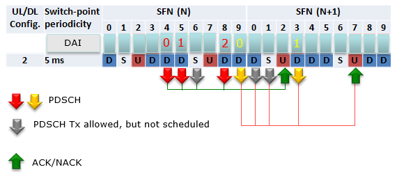
The grey arrows are new here, and the legend names them. The DAI row is shorter as a result, which is what the words underneath explain.
The legend gains a third entry : a grey arrow marks a subframe where PDSCH transmission was allowed but not scheduled.The counter skips those subframes : it counts transmissions rather than subframes.The first bundle now reads 0, 1, 2 : three scheduled subframes in place of four.The second bundle now reads 0, 1 : two scheduled subframes in place of four.So the count is not the subframe number : it is the position of that PDSCH inside its own bundle.
Just to make it clearer, I would suggest you to describe this illusteration into words. My version of description is as follows.
- Subframe 4,5,8 in a frame are bundled to subframe 2 in next subframe (Lets call the subframe 4,5,8 as Set A)
- Subframe 9,3 are bundled to subframe 7 (Lets call the subframe 9,3 as Set B)
- All of the subframe listed above are scheduled to transmit PDSCH.
- When scheduling PDSCH in subframe 4, eNB assigns the index(number) 0 to DAI field of the DCI because this is the first PDSCH transmission in a same set(Set A in this case).
- When scheduling PDSCH in subframe 5, eNB assigns the index(number) 1 to DAI field of the DCI because this is the second PDSCH transmission in a same set(Set A in this case).
- subframe 6 is NOT secheduled for PDSCH.
- When scheduling PDSCH in subframe 8, eNB assigns the index(number) 2 to DAI field of the DCI because this is the third PDSCH transmission in a same set(Set A in this case).
- When scheduling PDSCH in subframe 9, eNB assigns the index(number) 0 to DAI field of the DCI because this is the first PDSCH transmission in a same set(Set B in this case).
- subframe 0 is NOT secheduled for PDSCH..
- subframe 1 is NOT secheduled for PDSCH.
- When scheduling PDSCH in subframe 3, eNB assigns the index(number) 1 to DAI field of the DCI because this is the the second PDSCH transmission in a same set(Set B in this case).
Why DAI ?
As you see in the example shown above or shown in this not in more details, the number of Ack/Nack bits in PUCCH varies depending on Uplink/Downlink configuration and the real PDSCH scheduling within the pattern. If we assume that eNB always schedule PDSCH for every possible DL subframe (including special subframe) and all of the PDCCH (DCI) is successfully recieved and decoded by UE, the number of ACK/Nack Bits (Ack/Nack bit length) can be determined directly from Uplink/Downlink configuration, however in reality eNB does not always schedule PDSCH at every subframe and we cannot guarantee that UE would be able to successfully decode the PDCCH (DCI). In this case, how the UE can figure out the Ack/Nack Bit length ?
Let's think of a case shown below as an example and assume all the PDSCH is single codeword.
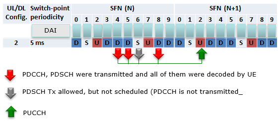
The picture above sets the question rather than answering it. The DAI row is left empty on purpose, and one subframe carries a grey arrow.
Three subframes carry a red arrow : the legend reads that the PDCCH and PDSCH were transmitted and all of them were decoded by the UE.One subframe carries a grey arrow : PDSCH transmission was allowed there but not scheduled, and no PDCCH was sent.The green arrow is the PUCCH : it carries the acknowledgements for the whole bundle.The DAI row is blank on purpose : the question is what the UE can work out without it.
Now let's assume that UE is trying to construct a UCI at SFN(N+1), subframe 2. According to the diagram above and assume that UE has successully decoded PDCCH and PDSCH transmitted from SFN(N), subframe 4,5,8 but didn't received any PDCCH/PDSCH at SFN(N), Subframe 6. Which Ack/Nack UCI the UE should send at SFN(N+1), subframe 2 ? Should it be '111' ? or '1101' ? If UE knows, eNB scheduled PDCCH only at SFN(N), subframe 4,5,8 (i.e, skipping SFN(N), subframe 6), then the UCI should be '111'. If UE knows, eNB scheduled PDCCH at SFN(N), subframe 4,5,6,8 and it failed to decode PDCCH at subframe 6. The UCI should be '1101'. However the problem is 'UE cannot figure out whether eNB sent PDCCH at subframe 6 or not'. Then how UE can construct the proper UCI in this case ? That's where DAI kicks in. DAI let UE figure out whether it recieved all the scheduled PDCCH/PDSCH or missed any PDCCH. To be honest, I don't think my written explanation here would be clear to you. Would following diagram would be any more help ? I hope it sounds clearer. If you can clearly understand the difference between case 1 and 2, it was successful for me to understand the basic concept/role of DAI.
Case 1 : Three scheduled and three decoded
Nothing was lost on the air here. The point is that the UE cannot know that on its own, because a subframe with no grant and a subframe whose grant it missed look the same to it.
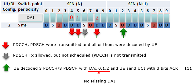
Case 1 fills the DAI row in. The answer is written into the legend rather than drawn in the picture.
The three DAI values are 0, 1 and 2 : they run without a gap in them.The legend states the outcome : the UE decoded 3 PDCCH and 3 PDSCH with DAI 0, 1, 2. It sends a UCI of 3 bits with ACK = 111.The note underneath gives the reason : No Missing DAI.A run with no gap means nothing was missed : the UE can size the codebook at three and stop there.
Case 2 : Four scheduled and three decoded
This is the same picture with one subframe changed, and the change is invisible to the UE. It decodes the same three grants as before, so whatever it works out has to come from what those three carry.
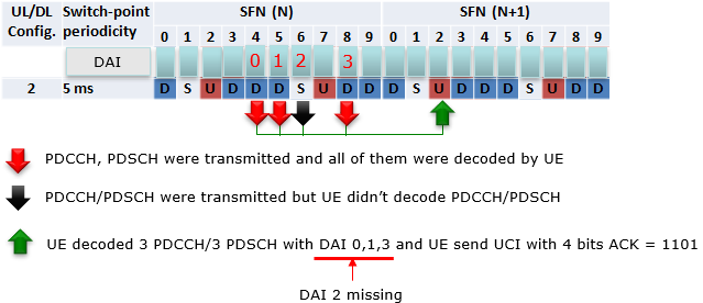
Case 2 keeps the same three decoded subframes and changes only what happened in the fourth. One arrow turns black, and the answer changes with it.
The black arrow is the new legend entry : the PDCCH and PDSCH were transmitted there, and the UE did not decode them.The DAI row now runs 0, 1, 2, 3 : the eNB counted four, because it scheduled four.The UE sees 0, 1 and 3 : the 2 never arrived. So the run it holds has a gap in it.The legend states the outcome : the UE sends a UCI of 4 bits with ACK = 1101.The zero in the third position is the missed one : the UE reports a NACK for the PDSCH it never saw.
The two cases are the same three decodes seen from the UE. Only the gap in the counter separates them, and the gap is what sets the length of the answer.
The DAI is a counter, not an identifier : it says how many have gone out, not which one this is.A missing value is the signal : the UE learns that it missed a grant from a number that never arrived.The codebook size follows from the highest count seen : three values ending at 2 give three bits. Three values ending at 3 give four.Two bits are enough because the count wraps : Table 7.3.1-1 gives every pattern a second meaning four counts later.
Reference
The two specifications below are the ones this page was checked against, in the versions named.
- 36.213 : 3GPP - E-UTRA; Physical layer procedures, v19.4.0. Clause 7.3 is the UE procedure for reporting HARQ-ACK, and Table 7.3.1-1 gives the value of the counter DAI and the total DAI.
- 36.212 : 3GPP - E-UTRA; Multiplexing and channel coding, v19.3.0. Its DCI format 0 field list is where the Downlink Assignment Index is given its two bits.