Even while there is no traffic between the network and UE, UE has to keep listening to Network. At least it should be ready to decode PDCCH. It means UE has to be "ON" all the time even when there is no traffic. But being ON all the time would drain the battery.
You may ask "Then why don't UE shut down (getting into a sleep mode) when there is no traffic ?". Sounds good, but what if Network tries to send some data to UE while the UE is in the sleep mode ?
Then what would be the ideal solution for this ? what is the ideal solution to save battery consumption and still does not lose chance of receiving the data that Network sent to UE ?
One of the solution for this is let UE get into sleeping mode for a certain period of time and wake up again checking if there is any data coming from the network and getting into sleeping mode again if there is no data and wake up again... repeaing this cycles. This kind of periodic repeatition of "sleep mode and wake up mode" is called DRX (Discontinous Reception".
Does it sound simple ? It may.. but in reality implemting DRX may not be as simple as you may expected because there should be well designed synchronization between UE and Network. In worst case, Network tries to send some data while UE is in sleep mode and UE tries to wake up when there is no data to be recieved. To prevent this kind of worst case scenario, UE and Network has a well defined agreement about when UE has to be in sleep mode and when UE has to wake up. This agreement is defined in 3GPP TS36.321 Section 5.7 for connected mode, and TS36.304
Section 7.1 for idle mode.
Now let's look into a little bit detailed aspect of CDRX (Connected Mode DRX) operation. Followings are the list of aspects that I want to talk about
- RRC Connection Reconfiguration for DRX Setting
- UE Capability Information for DRX Supportability
- Some misconception about CDRX
- How to test CDRX
- Get the Test Procedure and Log / Amarisoft TechAcademy
- Reference
RRC Connection Reconfiguration for DRX Setting
The network decides when the UE may sleep, and it has to say so in a message the UE is still awake to receive. That message is an RRC reconfiguration, and everything in this section follows from the handful of timers it carries.
In normal operation, UE has to be awake all the time and monitor PDCCH for every subframe meaning that it has to be awake all the time since it doesn't know exactly when the network will transmit the data for it. Logically there is no problem with this, but there would be a practical problem. It is power consumption issue on UE side. If UE is always up even when there is no data being transmitted to it from the network, it would be wasting the energy.
Then what would be the solution to save the energy on UE side. There may be several ways, but one of the most common way is to use DRX. DRX is a mechanism in which UE gets into sleep mode for a certain period of time and wake up for another period of time.
It sounds good. Then you may have a question. How can we synchronize UE-wakeup timing with Network transmission timing for the UE. If these two timing does not match, there can be a worst case where UE is awake but Network does not transmit anything or Network transmit something for the UE but UE is in sleep mode. One solution would be that Network decide when to let UE sleep and when towake it up and inform the timing to the UE using a RRC message.
In reality, Network informs UE of this timing using RRC ConnectionReconfiguration or RRC Connection Setup as follows (Following is the example configuration from RRC ConnectionReconfiguration, but you can do the samething in RRC Connection Setup as well).
Capture : an RRC Connection Reconfiguration as one network sent it. Nothing in it has been corrected against a specification.
    rrcConnectionReconfiguration-r8
     dedicatedInfoNASList: 1 item
         Item 0
             DedicatedInfoNAS: 27bd5ad9de05620ec101050403696d730902000000000000...
                ....
     radioResourceConfigDedicated
         drb-ToAddModList: 1 item
             ...
         mac-MainConfig: explicitValue (0)
             explicitValue
                 ul-SCH-Config
                     ...
                 drx-Config: setup (1)
                     setup
                         onDurationTimer: psf6 (5)
                         drx-InactivityTimer: psf1920 (20)
                         drx-RetransmissionTimer: psf16 (5)
                         longDRX-CycleStartOffset: sf1280 (13)
                             sf1280: 0
                         shortDRX
                             shortDRX-Cycle: sf10 (3)
                             drxShortCycleTimer: 10 shortDRX-Cycles
                 timeAlignmentTimerDedicated: infinity (7)
                 phr-Config: setup (1)
                     setup
                         ...
                 mac-MainConfig-v1020
         physicalConfigDedicated
             ....
- The DRX configuration sits deep in the tree. It hangs off radioResourceConfigDedicated, then mac-MainConfig, then drx-Config.
- The highlighted block is the whole of it, and it reads onDurationTimer psf6, drx-InactivityTimer psf1920, drx-RetransmissionTimer psf16, and longDRX-CycleStartOffset sf1280 with an offset of 0.
- shortDRX is set up in this one. Its shortDRX-Cycle is sf10 and its drxShortCycleTimer is 10 short cycles, so the short cycle covers 100 subframes before the long cycle takes over.
- The psf and sf prefixes count different things, because psf counts PDCCH subframes and sf counts subframes. An onDurationTimer of psf6 is therefore six PDCCH subframes, while a cycle of sf1280 is 1280 subframes.
Following is based on
DRX-Config ::=						CHOICE {
	release								NULL,
	setup								SEQUENCE {
		onDurationTimer						ENUMERATED {
												psf1, psf2, psf3, psf4, psf5, psf6,
												psf8, psf10, psf20, psf30, psf40,
												psf50, psf60, psf80, psf100,
												psf200},
		drx-InactivityTimer					ENUMERATED {
												psf1, psf2, psf3, psf4, psf5, psf6,
												psf8, psf10, psf20, psf30, psf40,
												psf50, psf60, psf80, psf100,
												psf200, psf300, psf500, psf750,
												psf1280, psf1920, psf2560, psf0-v1020,
												spare9, spare8, spare7, spare6,
												spare5, spare4, spare3, spare2,
												spare1},
		drx-RetransmissionTimer				ENUMERATED {
												psf1, psf2, psf4, psf6, psf8, psf16,
												psf24, psf33},
		longDRX-CycleStartOffset		CHOICE {
			sf10							INTEGER(0..9),
			sf20							INTEGER(0..19),
			sf32							INTEGER(0..31),
			sf40							INTEGER(0..39),
			sf64							INTEGER(0..63),
			sf80							INTEGER(0..79),
			sf128							INTEGER(0..127),
			sf160							INTEGER(0..159),
			sf256							INTEGER(0..255),
			sf320							INTEGER(0..319),
			sf512							INTEGER(0..511),
			sf640							INTEGER(0..639),
			sf1024							INTEGER(0..1023),
			sf1280							INTEGER(0..1279),
			sf2048							INTEGER(0..2047),
			sf2560							INTEGER(0..2559)
		},
		shortDRX							SEQUENCE {
			shortDRX-Cycle						ENUMERATED	{
													sf2, sf5, sf8, sf10, sf16, sf20,
													sf32, sf40, sf64, sf80, sf128, sf160,
													sf256, sf320, sf512, sf640},
			drxShortCycleTimer					INTEGER (1..16)
		}		OPTIONAL													-- Need OR
	}
}

DRX-Config-v1130 ::=					SEQUENCE {
	drx-RetransmissionTimer-v1130			ENUMERATED {psf0-v1130}	OPTIONAL,	--Need OR
	longDRX-CycleStartOffset-v1130			CHOICE {
		sf60-v1130								INTEGER(0..59),
		sf70-v1130								INTEGER(0..69)
	}																OPTIONAL,	--Need OR
	shortDRX-Cycle-v1130					ENUMERATED	{sf4-v1130}	OPTIONAL	--Need OR
}

DRX-Config-v1310 ::=					SEQUENCE {
	longDRX-CycleStartOffset-v1310		SEQUENCE {
		sf60-v1310								INTEGER(0..59)
	}																OPTIONAL	--Need OR
}
Every value in the capture above is still in the enumeration, and the number in brackets beside each one is its index counting from zero. All five line up: psf6 is the sixth entry of onDurationTimer, psf1920 the twenty first of drx-InactivityTimer, psf16 the sixth of drx-RetransmissionTimer, sf1280 the fourteenth of longDRX-CycleStartOffset, and sf10 the fourth of shortDRX-Cycle.
Later releases added values rather than fields. DRX-Config-v1130 adds a zero length retransmission timer, two more long cycle lengths at 60 and 70 subframes, and a short cycle of 4 subframes. DRX-Config-v1310 adds a 60 subframe long cycle of its own.
Following table shows the meaning of each DRX parameters.
|
DRX Parameter |
Description |
|
DRX Cycle |
The duration of one 'ON time' + one 'OFF time'. (This value does not explicitely specified in RRC messages. This is calculated by the subframe time and longdrx-CycleStartOffset) |
|
onDurationTimer |
The duration of 'ON time' within one DRX cycle |
|
drx-Inactivity timer |
Specify how long UE should remain 'ON' after the reception of a PDCCH. When this timer is on UE remains in 'ON state' which may extend UE ON period into the period which is 'OFF' period otherwise. (See the figure for < case 2 > below) |
|
drx-Retransmission timer |
Specifies the maximum number of consecutive PDCCH subframes the UE should remain active to wait an incoming retransmission after the first available retransmission time |
|
shortDRX-Cycle |
DRX cycle which can be implemented within the 'OFF' period of a long DRX Cycle.(See the figure for < case 4 > below) |
|
drxShortCycleTimer |
The consecutive number of subframes the UE shall follow the short DRX cycle after the DRX Inactivity Timer has expired(See the figure for < case 4 > below) |
Before we go into further detail, let me give you a couple of figures that would help your understanding.
Case 1 : Only Long DRX Cycle is configured and No PDCCH is received during the cycle.
This is the case the other three are measured against. Nothing interrupts the cycle here, so the picture shows the configuration behaving exactly as the timers describe it, and the ON time and the ON Duration are the same thing.
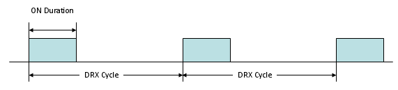
- Three ON pulses run across two full cycles. The bracket above the first pulse is labelled ON Duration, and the brackets underneath are labelled DRX Cycle.
- Nothing extends a pulse here. With no PDCCH arriving in the cycle, the ON time is exactly the ON Duration, and every pulse is the same width.
Case 2 : Only Long DRX Cycle is configured and a PDCCH is received during a cycle (You will notice the real 'ON time' May get extended depending on DRX Inactivity Timer and when the PDCCH is recieved as shown in thick Blue line).
One PDCCH is enough to change that. The cycle and the ON Duration are unchanged in the picture below, and the only thing that differs is where the ON period ends. The drx-InactivityTimer is what moves it.
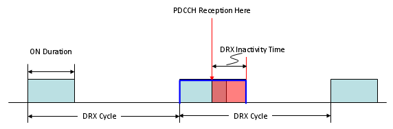
- The middle pulse is outlined in blue and it is wider than the other two. A red arrow labelled PDCCH Reception Here points down into it, and a bracket labelled DRX Inactivity Time spans the red shaded part that follows.
- The ON Duration has not changed. What changed is the ON time, which now runs to the end of the inactivity timer rather than to the end of the ON Duration.
Case 3 : Only Long DRX Cycle is configured and a PDCCH and DRX Command MAC CE are received during a cycle (You will notice the real 'ON time' MAY get shorter depending on exactly when DRX Command MAC CE is received as shown in thick Blue line).
The network can also move that boundary the other way. The case above shows the UE staying awake longer than the ON Duration alone would give, and this one shows the network ending the ON period early, before either timer would have expired.
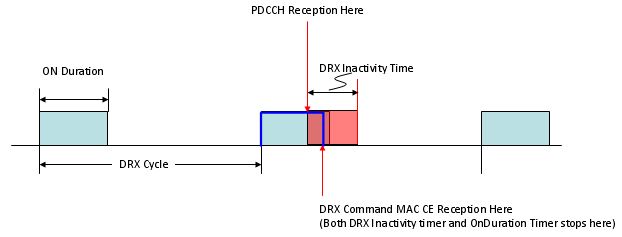
- A second red arrow points up into the same pulse from below. It is labelled DRX Command MAC CE Reception Here, with the note that both the DRX Inactivity timer and the OnDuration Timer stop there.
- The blue outline ends at that arrow. The lighter red to its right is the ON time the UE would have had without the MAC CE, so this case shortens the ON time where the case above lengthens it.
Case 4 : Both Long DRX Cycle and Short DRX Cycle are configured and No PDCCH is received during the cycle. This may be the most complicated case related to DRX cycle. Overall logic goes like this
The three cases above run one cycle length. This one runs two, and the question it answers is when the UE moves between them. That transition is the part of the configuration the first three never exercise, and the numbered steps below set it out before the picture does.
i) When C DRX is configured and the last DCI (PDCCH) arrived
ii) drx-inactivityTimer starts and 'Wake-up status' continues until the drx-inactivityTimer expires.
iii) After drx-inactivityTimer expired and the shortDrxCycle condition meet, the shortDrxCycle starts and drxShortCycleTimer starts.
iv) If there is no DCI(no PDCCH) until drxShortCycleTimer expires, Long Drx Cycle starts.
v) If any DCI (PDCCH) arrives during the wake-up period of any DRX cycle, go to step ii).
Following is one example showing this overall logic. This is just one example.. there can be almost infinite number of different combination is possible.
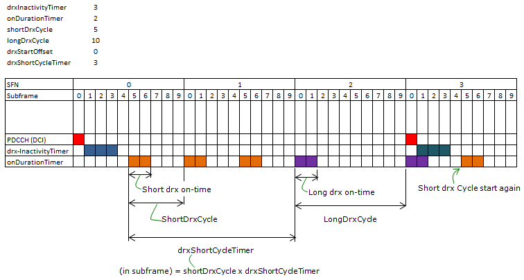
- The parameters are listed at the top left: drxInactivityTimer 3, onDurationTimer 2, shortDrxCycle 5, longDrxCycle 10, drxStartOffset 0 and drxShortCycleTimer 3.
- The grid runs four radio frames, SFN 0 to 3, with the ten subframes of each numbered underneath, and three signal rows below that.
- A red PDCCH (DCI) cell sits at SFN 0 subframe 0. The drx-InactivityTimer row runs blue for the next three subframes, which is the value of that timer.
- The onDurationTimer row is coloured two subframes at a time, which is the value of that timer. The first three pairs are five subframes apart, and the bracket labelled drxShortCycleTimer spans all three of them.
- The purple pairs are the long cycle, ten subframes apart. A second DCI at SFN 3 subframe 0 restarts the inactivity timer, and the note on the right marks where the short cycle starts again.
One label in the picture is misspelt. The bracket under the long cycle reads LongDrxCyde where the others read the parameter names correctly.
Let me give you a couple of question ?
i) What would be the best period for sleeping and wake-up period ?
ii) What kind of problem would happen if sleeping time is too short whereas wake-up time is very long ?
iii) What kind of problem would happen if sleeping time is too long whereas wake-up time is very short ?
There would be no best answer for the question i). The answer will be different depending on situation.
The answer to question ii) would be that you would not save much energy on UE side since UE is awake most of the time.
The answer to question iii) would be that you would save much energy on UE side but there may be longer delay for data reception when network wants to send some data.
Now let's get into further details on exactly what happens on UE side when this DRX is working. This is very complicated process especially if both long DRX cycle and short DRX cycle are configured. Don't try to understand all the details at once. Just try to go through this process as often as possible. Try to understand only one if() statement at once.
The DRX procedure of 36.321 clause 5.7, written as pseudo code. This is a rendering of the procedure rather than specification text.
if(drx-Config == setup) {
      if((Short DRX Cycle  is configured/activated)
           && ( [(SFN * 10) + subframe number] mod (shortDRX_Cycle) == (drxStartOffset) mod (shortDRX_Cycle)) {
                   start onDurationTimer;
      }

       if((Long DRX Cycle  is configured/activated)
           && ( [(SFN * 10) + subframe number] mod (longDRX_Cycle) == (drxStartOffset) ) {
                   start onDurationTimer;
      }

       if( (a HARQ RTT Timer expires in this subframe)
           && (the data in the soft buffer of the corresponding HARQ process was not successfully decoded) {
                   start the drx-RetransmissionTimer for the corresponding HARQ process;
      }

       if( DRX Command MAC control element is received ) {
                   stop onDurationTimer;
                   stop drx-InactivityTimer;
      }

       if( (drx-InactivityTimer expires)
           || (DRX Command MAC control element is received in this subframe) {
                   if (the Short DRX cycle is configured ) {
                            start or restart drxShortCycleTimer;
                            use the Short DRX Cycle;
                   } else {
                            use the Long DRX cycle;
                   }
      }

       if( drxShortCycleTimer expires in this subframe ) {
                   use the Long DRX cycle;
      }

       if( during the Active Time, for a PDCCH-subframe,
           if the subframe is not required for uplink transmission for halfduplex FDD UE operation and
           if the subframe is not part of a configured measurement gap) {
                   monitor the PDCCH;
                   if (PDCCH indicates a DL transmission ||  DL assignment has been configured for this subframe ) {
                            start the HARQ RTT Timer for the corresponding HARQ process;
                            stop the drx-RetransmissionTimer for the corresponding HARQ process;
                   }

                   if (the PDCCH indicates a new transmission (DL or UL) ) {
                            start or restart drx-InactivityTimer;
                   }
      }

       if( not in the Active Time) {
                   CQI/PMI/RI on PUCCH and SRS shall not be reported;
       }
}
The pseudo code above is the Release 8 shape of the procedure. 36.321 v19.3.0 has grown around it in four places, and none of the four changes what is written above.
- Uplink retransmission has a timer of its own. An UL HARQ RTT Timer expiring starts drx-ULRetransmissionTimer, and neither of those appears above.
- Two DRX Command MAC control elements exist now. The plain one stops onDurationTimer and drx-InactivityTimer, exactly as above. A Long DRX Command MAC control element does that and also stops drxShortCycleTimer, which sends the UE straight to the long cycle.
- Short TTI carries its own pair, drx-RetransmissionTimerShortTTI and drx-ULRetransmissionTimerShortTTI.
- Active Time is defined rather than assumed. 36.321 lists five ways to be in it, and a running timer is only the first. A pending Scheduling Request on PUCCH keeps the UE in Active Time, and so does a running mac-ContentionResolutionTimer. So does the window after a Random Access Response, until a PDCCH addressed to the C-RNTI arrives.
That last one is worth carrying into the next sections. A UE can be awake because it is waiting for something it asked for, and no line of the configuration says so.
Example
The DRX parameters that I used are as follows. As you see, only Long DRX is configured in this example and I didn't enable the short DRX for simplicity.
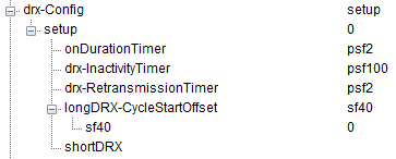
- The tree is the configuration behind the spreadsheet linked below it. It reads onDurationTimer psf2, drx-InactivityTimer psf100, drx-RetransmissionTimer psf2, and longDRX-CycleStartOffset sf40 with an offset of 0.
- shortDRX appears in the tree with nothing under it, which is what the paragraph above means by not enabling the short DRX for this example.
The network owns the schedule : every timer arrives in an RRC message, and the UE only follows it.The ON time is not the ON Duration : a PDCCH extends it and a DRX Command MAC CE cuts it short, which is the whole difference between the four cases above.The short cycle is a transition, not a mode : drxShortCycleTimer counts how many short cycles run before the long one takes over.
Click here to download the analysis file.
Overall procedure that I applied is as follows.
i) < Persistant Scheduling for both DL/UL >
ii) RRC Connection Reconfiguration (Notifies the DRX configuration to UE)
iii) Configure DRX parameters on Network simulator side
iv) Receive RRC Connection Reconfiguration Complete
v) Stop transmit PDCCH (DCI 0/DCI 1) from here to all the way to the end.
You may see from the spreadsheet that was linked above that the DRX ON does not start right away after step ii). It is because we still need to send PDCCH for step iv).
Just open up the spreadsheet linked above and follow through each row and at every row ask your self "Why this should DRX ON ?" or "Why this should be DRX OFF". This is the only way you can understand the DRX mechanism in full detail.
This example is the simplest case. so you have to make it sure to understand at least this example. I will keep adding examples with various complexity.
UE Capability Information for DRX Supportability
The network can configure a feature the UE cannot always perform. CDRX is optional, so the network has to be told before it configures anything, and the message below is where the UE answers.
Even though CDRX is a very important feature in terms of energy saving on UE side and a lot of live network enables this feature, it is not the mandatory requirement on UE. Therefore, even though most of UE would support this feature, there would be some UE (especially UE released at very early stage of LTE) that may not support this feature. So UE needs to inform the network about CDRX supportability and Network can optionally enable or disable based on UE capability and Network operator's requirement. CDRX supportability is informed to network via UE Capability Information message as shown below.
Capture : a UE Capability Information as one UE sent it. Nothing in it has been corrected against a specification.
ueCapabilityInformation-r8
     ue-CapabilityRAT-ContainerList: 1 item
         Item 0
             UE-CapabilityRAT-Container
                 rat-Type: eutra (0)
                 ueCapabilityRAT-Container: c9980050c08616082058b58fff15b1ffe2fe3ffc53c7ff8b...
                     UE-EUTRA-Capability
                         accessStratumRelease: rel10 (2)
                         ue-Category: 4
                         pdcp-Parameters
                         ..
                         phyLayerParameters
                             ....
                         rf-Parameters
                             ....
                         measParameters
                             ....
                         featureGroupIndicators: 7fcffeb2
                             0... .... = Indicator 1: ...
                             .1.. .... = Indicator 2: ...
                             ..1. .... = Indicator 3: ...
                             ...1 .... = Indicator 4: Short DRX cycle - Supported
                             .... 1... = Indicator 5: Long DRX cycle;
                                                   DRX command MAC control element - Supported
                             .... .1.. = Indicator 6: ....
- The answer arrives inside a container rather than as plain fields, where rat-Type reads eutra and the DRX answer sits in the featureGroupIndicators bit string, which reads 7fcffeb2 here.
- Two of those bits carry it. Indicator 4 is Short DRX cycle, and Indicator 5 is Long DRX cycle together with the DRX command MAC control element. Both read Supported in this capture.
- The accessStratumRelease reads rel10 and the ue-Category reads 4, which is the context the indicators sit in.
Two indicators, not one : the short cycle and the long cycle are answered separately in the feature group bits.The long cycle bit covers the MAC CE too : Indicator 5 answers for the long cycle and for the DRX command MAC control element together, so a UE cannot take one without the other.Capability comes before configuration : the network reads these bits before it sends the reconfiguration in the section above.
Some misconception about CDRX
Two beliefs about CDRX are common and both are wrong. Both come from reading the configuration and stopping there. The configuration only sets the parameters, and the procedure decides what happens.
I often see some of the misconception about CDRX and followings are some of the examples
- If Network enables CDRX configuration in RRC Connection Reconfiguration message, UE MUST go to sleep and eNB MUST stop transmitting the data IN ANY SITUATION according to the specified Cycle. But this is not true. The precondition to go into DRX mode (sleep mode) is that there is no data(PDCCH, MAC CE) during the onTime. If there is any data transmitted to UE during onTime, the onTime gets extended. In worst case, if there is data being continuously transmitted to UE, UE/eNB will never gets into the sleep mode.
- If CDRX gets into sleep mode, UE energy consumption should decrease. In theory, this is true and this is one of the most important motivation of employing CDRX. However, you may see some UE (especially at early stage of development) that does not show any outstanding reduction of energy consumption even when the DRX is in sleep period. To make the best use of CDRX, UE maker (and chipset maker) properly implement the chipset in such a way that UE Radio Stack is guaranteed to go into sleep mode (turning off most of unecessary processes and timers etc).
A third belief is worth adding here, because the measurement at the end of this page settles it. A shorter DRX cycle looks like more sleep in every second, and the two traces in the last section say otherwise. They were taken with a 320 subframe cycle and with a 40 subframe cycle, and the current between bursts returns to zero only on the longer one. A cycle short enough to stop the receiver reaching its deep state leaves a floor of current behind, and that floor is paid continuously rather than once per wake-up.
A fourth belief is that DRX is a downlink mechanism. 36.321 clause 5.7 does not read that way. The Active Time includes the window in which an uplink grant for a pending HARQ retransmission can arrive, while there is data in the corresponding HARQ buffer. It also includes the time a Scheduling Request is pending on PUCCH. The procedure also runs an uplink retransmission timer of its own. A UE with nothing to receive and something to send is not asleep.
The clause is broader still in what it covers. It controls PDCCH monitoring not only for the C-RNTI but for the TPC-PUCCH-RNTI, the TPC-PUSCH-RNTI, the Semi-Persistent Scheduling C-RNTI and several others where they are configured. Reading DRX as a rule about user data alone misses most of what it switches off.
A configured cycle is a permission, not a promise : the UE sleeps only when an ON time passes with no PDCCH and no MAC CE.36.321 says the same thing in its Active Time definition : a pending Scheduling Request or a running contention resolution timer keeps the UE awake whatever the cycle says.Sleeping in the protocol is not sleeping in the silicon : the current only falls if the implementation actually shuts the receiver and the timers down.A shorter cycle is not automatically a cheaper one : the measurement in the last section shows the floor between bursts rising when the cycle shortens.
How to test CDRX
Configuring DRX takes a few lines in a message, and confirming that it works takes a measurement. The steps below run from the cheapest check to the only conclusive one, and the two pictures at the end are what the conclusive one looks like.
Configuring DRX in RRC Connection Reconfiguration would be relatively simple, but verifying on whether the DRX is properly working is not that simple. Since this happens at the subframe timing, it is not possible to test the operation with eye balling. There are several steps you have to check.
- i) Make it sure there is no data traffic long enough to trigger CDRX sleep mode (you may use wireshark to verify this)
- ii) If you have access to eNB log, you have to check the data transmission status at each subframe and confirm that there is no data transmission at MAC/PHY level.
- iii) If you have access to UE log, you have to check the data reception or SR(Scheduling Request)/BSR(Buffer Status Report) for long enough to trigger CDRX sleep mode.
- iv) The most conclusive verification should come from the measurement of real energy consumption on UE side. Even though all the previous conditions are met, UE energy consumption (current consumption) does decrease during CDRX sleep mode there is no point of using this technology. You would see current consumption pattern as shown below (marked as C-DRX) if CDRX is properly working. If you want to do exact measurement the sleeping /wake-up time on UE side during CDRX operation, you would need a current measurement equipment that supports very high sampling rate (very short sampling time). I used a Keysight(Agilent) N67XX family for this test.
Following illustration shows overall pattern of current consumption during the typical operation of mobile phone. In this page, just pay attention to the section labeled as C-DRX.
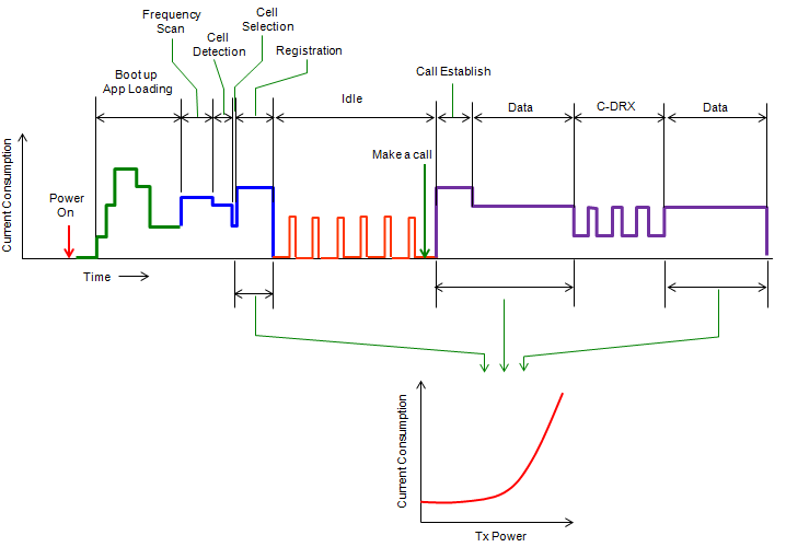
- The trace covers the whole life of a call, with current consumption up the page and time across it. The phases are labelled along the top: Boot up and App Loading, Frequency Scan, Cell Detection, Cell Selection, Registration, Idle, Call Establish, Data, C-DRX and Data.
- The Idle stretch is a run of narrow pulses on a floor near zero, which is the paging cycle rather than anything connected.
- The C-DRX stretch sits between the two Data stretches. Data is a flat high level, and C-DRX reaches the same height in pulses with a lower floor between them.
- Three arrows run down from the Data, C-DRX and Data windows to an inset plot of current consumption against Tx power, and that curve rises steeply at the top of its range.
Following is an example of real current consumption measurement during the DRX cycle (if you use the high sampling power analyzer) you can measure exact timing of wake-up /sleeping time. You would notice that depending on DRX configuration the baseline current consumption would be different and the decreasing the baseline would be one of the important optimization parameters in terms of energy consumption.
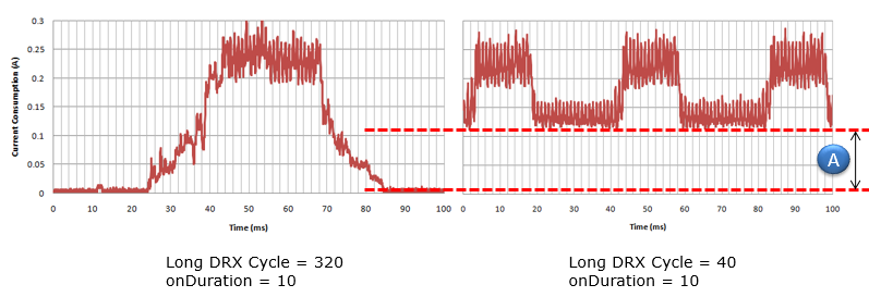
- Two measured traces sit side by side, both spanning 100 ms, both with current consumption in amperes up the page.
- The left one is captioned Long DRX Cycle = 320, onDuration = 10. One burst rises to about 0.25 A, and the current sits at zero on both sides of it.
- The right one is captioned Long DRX Cycle = 40, onDuration = 10, and three bursts fit into the same 100 ms. The bursts reach the same height as the one on the left.
- The difference is the floor, and the picture marks it. Two red dashed lines and the circled A measure the current between bursts. That current sits near 0.1 A on the right and at zero on the left.
A shorter cycle therefore does more than add wake-ups. It also raises the current the UE draws while it is supposed to be asleep, and that floor is the baseline the paragraph above calls an optimisation parameter.
Only current proves it : the log checks say the network stopped sending, and the measurement says the UE stopped listening.The baseline matters as much as the duty cycle : the measurement above shows the floor between bursts rising when the cycle shortens.The sampling rate decides what is visible : a subframe is one millisecond, so an instrument that averages over longer than that hides the thing being measured.
Reference
The documents below are the sources for the procedure and for the configuration on this page. A version is named only where the text was read in that version.
- 36.321 : 3GPP - E-UTRA; Medium Access Control (MAC) protocol specification, v19.3.0. Clause 5.7 is the DRX procedure, and it is what the pseudo code above was checked against.
- 36.331 : 3GPP - E-UTRA; Radio Resource Control (RRC) protocol specification, v19.3.0. DRX-Config is the source of the ASN.1 tile above and of the enumeration indices the capture is checked against.