LAA stands for Licence Assisted Access. Like LTE-U, this is a kind of technology to transmit LTE signal in unlicensed frequency range. However, unlike LTE-U, LAA use a special physical layer frame structure called Frame Structure Type 3 which didn't exisit before. This new frame structure is designed to make LTE signal similar to WLAN burst and make the LTE signal to better coexist with the existing WLAN operation.
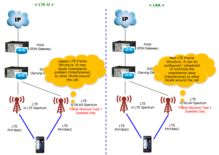
Followings are the list of topics that will be described in this page.
- Fundamental Characteristics of LAA
- Frequency and EARFCN
- Scheduling Mechanism for LAA
- DCI Format 1C
- UE Capability Information for LAA
- RRC Connection Recofngiruation - Adding LAA as a SCC
- RRC Connection Recofngiruation - Measurement Configuration for LAA Cell
- Coexistance with WLAN - LBT and CSAT
- Reference
Fundamental Characteristics of LAA
There are several fundamental characteristics of LAA and most of these characteristics are based on the properties of Frame Structure Type 3. You may find the summary of these characteristics from various documents. Instead of putting my own comments, I would introduce those summaries from a few different sources.
36.211 V13.1.0. Following description is all for now. I think the green part is same as the existing frame type (Type 1 / Type 2) and the blue part is unique to Type 3.
- Frame structure type 3 is applicable to LAA secondary cell operation with normal cyclic prefix only. Each radio frame is Tf = 307200⋅Ts =10ms long and consists of 20 slots of lengthTslot = 15360⋅Ts = 0.5 ms , numbered from 0 to 19. A subframe is defined as two consecutive slots where subframe i consists of slots 2i and 2i +1 .
- The 10 subframes within a radio frame are available for downlink transmissions. Downlink transmissions occupy one or more consecutive subframes, starting anywhere within a subframe and ending with the last subframe either fully occupied or following one of the DwPTS durations
Small Cell Forum - nFAPI and FAPI specifications 3.2.3 LBT Procedures summarizes the characteristics as follows (basically almost same as 3GPP description).
- Uplink Transmissions are not allowed
- Downlink Transmissions may start anywhere within a subframe and occupy one or more subframes
- The last subframe in a downlink transmission burst may end at the subframe boundary or any one of the DwPTS durations defined for frame structure type 2.
- When configured with capability of initial partial subframe, the LAA SCell shall begin transmission of PDSCH/PDCCH/EPDCCH in the second slot of the subframe.
Extending LTE to unlicensed spectrum globally – LAA (Qualcomm) summarizes the LAA as follows (These are not described explicitely in 3GPP, but it well describes on the motivation of LAA).
- Fair Wi-Fi coexistence a key principle in LAA design
- LAA is designed to protect Wi-Fi
- Select clear channel: Dynamically avoid Wi-Fi
- Sharing the channel fairly: “Listen before talk” (LBT)
- Release unlicensed channel at low traffic
- LBT ensures fair sharing in unlicensed 5 GHz
Two of the statements above were true when they were written and are not true now. The quotation carries its own version stamp, 36.211 v13.1.0, and clause 4.3 of that release said the ten subframes in a radio frame are available for downlink transmissions.
The same clause in 36.211 v19.3.0 says they are available for downlink or uplink transmissions, and adds that uplink transmissions occupy one or more consecutive subframes. Release 14 brought uplink to frame structure type 3 under the name eLAA. The Small Cell Forum line above, that uplink transmissions are not allowed, describes Release 13.
Frame structure type 3 belongs to LAA secondary cells : 36.211 clause 4.3 says so, and allows normal cyclic prefix only.A downlink burst may start anywhere inside a subframe : it ends either at a subframe boundary or on one of the DwPTS durations of frame structure type 2.The downlink only rule belongs to Release 13 : 36.211 v19.3.0 clause 4.3 allows uplink on the same frame structure.The quotation above was left as it stands : it names its own version, so the later text is quoted here beside it rather than written over it.
Frequency and EARFCN
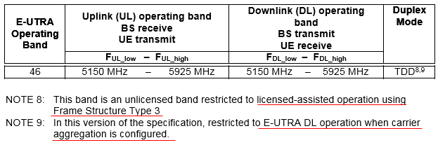
As of now (Rel 14), only one band is specified for LAA in 3GPP which is band 46. As shown in the following table, LAA is specified to be TDD mode but overal mechanism of the operation would be more similar to FDD operation.
< 36.101 Rel14 - Table 5.5-1 E-UTRA operating bands >
EARFCN (Downlink Channel Number) allocated for LAA (Band 46) is as follows. (NOTE : In case of LTE, if a UE support a certain band, it tend to work with any channel number. However, as far as I experienced (as of Sep 2017), some UE tend to work with only specific channel numbers in this band. So if you are to test LAA, check if your DUT has any of channel number restrictions with your DUT)
< 36.101 Rel14 - Table 5.7.3-1: E-UTRA channel numbers>

Both screenshots above come from 36.101, and one of the footnotes has since been withdrawn. In the release they were taken from, band 46 carried notes 8 and 9. Note 9 read that the band is restricted to E-UTRA downlink operation when carrier aggregation is configured.
36.101 v20.0.0 Table 5.5-1 gives band 46 note 8 alone. Note 8 still reads that the band is unlicensed and restricted to licensed-assisted operation using frame structure type 3, and the range is unchanged at 5150 to 5925 MHz. The downlink only footnote has gone, which matches the uplink that 36.211 added to frame structure type 3.
A second band has appeared as well. The same table gives band 49, 3550 to 3700 MHz, note 16, and note 16 reads that the band is restricted to licensed-assisted operation using frame structure type 3. The count in the paragraph above, one band as of Release 14, is now two.
Band 46 is 5150 to 5925 MHz and TDD : unchanged between the screenshot above and 36.101 v20.0.0.Its downlink only footnote has been withdrawn : note 9 in the screenshot is no longer attached to the band.Band 49 is the second licensed-assisted band : 3550 to 3700 MHz, under note 16 of the same table.The channel numbers have not moved : 36.101 Table 5.7.3-1 still gives band 46 an offset of 46790 and a range of 46790 to 54539.
Scheduling Mechanism for LAA
LAA scheduling is done by the combination of regular DCI (DCI1, DCI2, DCI2A etc) and LAA specific DCI 1C (DCI 1C has been used for regular LTE operation but in LAA it is used to carry LAA specific information).
Even though a LAA burst can span multiple subframes, the scheduling DCI(DCI1, DCI2, DCI2A etc) is being transmitted at every subframe that carries PDSCH. However, there is some issues that cannot be handled by the regular scheduling DCI. It is due to following LAA burst characteristic as stated below.
Downlink transmissions occupy one or more consecutive subframes, starting anywhere within a subframe and ending with the last subframe either fully occupied or following one of the DwPTS durations
In regular LTE subframe (Frame Type 1 or 2), the downlink transmission always start and end with subframe boundary(I assume that PCFICH and Control is part of downlink transmission). However, the statement above says in LAA case the downlink transmission may not start and end with subframe boundary.
Now the question is how UE can figure out the exact starting and ending point within the starting and ending subframe if they are not start/end with subframe boundary. To provide these additional information to UE, DCI format 1C is used in addition to the regular scheduling DCI.
i) If there is regular scheduling DCI only DCI (DCI1, DCI2, DCI2A etc), it is assumed that all the symbol in the subframe is carrying LAA data.
ii) If there is both regular scheduling DCI and DCI 1C, the subframe(current subframe) or next subframe may or may not be partial subframe(subframe carrying data in less than 14 OFDM symbol).
iii) If there no DCI at all, the subframe does not transmit any LAA data.
Example 01
The table and the picture below show the same two radio frames twice, once as rows and once as a timeline. The row to follow through both is the DCI 1C one: where it appears, and what number it carries when it does.
Following is an example of LAA scheduling.
|
SFN |
Subframe |
PDCCH(DCI format) |
Comments |
|
0 |
0 |
PDCCH(DCI 2A) |
All 14 OFDM Symbols transmit LAA data |
|
1 |
PDCCH(DCI 2A) |
All 14 OFDM Symbols transmit LAA data |
|
|
2 |
PDCCH(DCI 1C Config = 11,DCI 2A) |
The first 9 OFDM Symbols transmit LAA Data |
|
|
3 |
No PDCCH |
NO LAA Data |
|
|
4 |
No PDCCH |
NO LAA Data |
|
|
5 |
PDCCH(DCI 1C Config = 7,DCI 2A) |
All 14 OFDM Symbols transmit LAA data |
|
|
6 |
No PDCCH |
NO LAA Data |
|
|
7 |
No PDCCH |
NO LAA Data |
|
|
8 |
No PDCCH |
NO LAA Data |
|
|
9 |
No PDCCH |
NO LAA Data |
|
|
1 |
0 |
PDCCH(DCI 2A) |
All 14 OFDM Symbols transmit LAA data |
|
1 |
PDCCH(DCI 2A) |
All 14 OFDM Symbols transmit LAA data |
|
|
2 |
PDCCH(DCI 2A) |
All 14 OFDM Symbols transmit LAA data |
|
|
3 |
PDCCH(DCI 1C Config = 11,DCI 2A) |
The first 9 OFDM Symbols transmit LAA Data |
|
|
4 |
No PDCCH |
NO LAA Data |
|
|
5 |
PDCCH(DCI 2A) |
All 14 OFDM Symbols transmit LAA data |
|
|
6 |
PDCCH(DCI 1C Config = 7,DCI 2A) |
All 14 OFDM Symbols transmit LAA data |
|
|
7 |
No PDCCH |
NO LAA Data |
|
|
8 |
No PDCCH |
NO LAA Data |
|
|
9 |
No PDCCH |
NO LAA Data |
If you can translate the table above into the following illustration, you are already pretty familiar with the LAA scheduling.
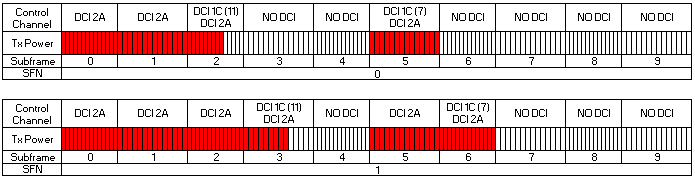
The two numbers beside DCI 1C are values of the 'Subframe configuration for LAA' field, and 36.213 Table 13A-1 turns them into symbol counts. 11 is 1011, which the table reads as nine symbols occupied in the current subframe. 7 is 0111, which it reads as fourteen symbols in the current subframe and at least the first symbol of the next subframe not occupied.
Both values mark the end of a burst, and they mark it in two different ways. The value 11 stops the burst partway through its own subframe. The value 7 fills its own subframe and excludes the start of the following one. The comments column of the table above states the first of those and leaves the second implicit.
Config 11 ends the burst inside the subframe that carries it : 36.213 Table 13A-1 reads 1011 as nine occupied symbols in the current subframe.Config 7 ends the burst at a subframe boundary : 0111 reads as fourteen symbols in the current subframe, with at least the first symbol of the next one unoccupied.Every occupied subframe also carries a scheduling DCI : DCI 2A appears in each of them, and DCI 1C appears only where the burst ends.No DCI means no LAA data : the picture leaves the transmit power row white wherever the control channel row reads NO DCI.
DCI Format 1C
One DCI format tells the UE where a burst stops, and its CRC is scrambled by CC-RNTI rather than by the UE's own identity. The table below lists what Release 13 puts in it. Two fields is the whole of it, and one of them is padding.
|
Field Name |
Length (Bits) |
Comment |
|
Subframe configuration for LAA |
4 |
Refer to 36.213 - Table 13A-1 |
|
Reserved |
|
bit padding until the size is equal to that of format 1C used for very compact scheduling of one PDSCH codeword |
< 36.213 - Table 13A-1: Subframe configuration for LAA in current and next subframe >
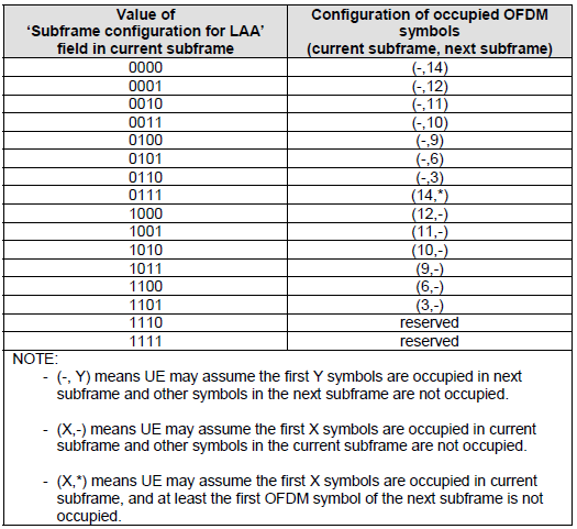
NOTE : The word 'occupied' mean 'occupied by LAA signal / LAA PDSCH is allocated for the specified subframe / symbols'.
36.213 clause 13A adds three rules the table does not show. The first is timing. A UE may detect a CC-RNTI DCI in subframe n-1 or in subframe n, and may apply the field to subframe n either way. That is why half the rows describe the next subframe rather than the current one.
The second is where to look. The UE monitors two PDCCH candidates for this DCI, one at aggregation level 4 on CCEs 0 to 3 and one at aggregation level 8 on CCEs 0 to 7. The search space is those two positions and nothing else.
The third concerns measurement. The UE may see no CC-RNTI DCI in subframe n or in subframe n-1, or only ones carrying 1110 or 1111. It is then not required to use subframe n for updating its CSI measurement. An unoccupied subframe therefore does not pull the reported channel quality down.
One field has been added since. 36.213 clause 13A adds a second field to the same DCI once the SCell is configured for uplink transmissions. That field is 'UL duration and offset', and it is read against Table 13A-2. The table above is the Release 13 form, and it is still correct for a downlink only cell.
The DCI may arrive one subframe early : 36.213 clause 13A lets the UE apply a field detected in subframe n-1 to subframe n.The search space is two candidates : aggregation level 4 on CCEs 0 to 3, and aggregation level 8 on CCEs 0 to 7.Values 1110 and 1111 are reserved : 36.213 Table 13A-1 marks them so, and clause 13A uses them as the exception in its CSI rule.Uplink adds a second field : 'UL duration and offset' joins the same DCI once the SCell is configured for uplink transmissions.
UE Capability Information for LAA
Like many other features of LTE, LAA is a feature that should be informed by UE to the network. If UE is to support LAA, you would see following three items in UE Capability Information message.
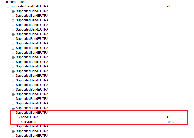
The list in the picture above is the supported band list, and one entry in it is ringed. That entry carries bandEUTRA 46 with halfDuplex set to FALSE, which is how the UE declares the band.
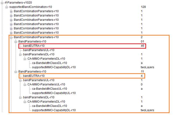
Having the band is not the same as being able to use it. The picture below opens the supported band combination list, where band 46 has to appear beside a licensed band before it can carry anything.
The picture below opens the feature bits themselves. The branch to read is laa-Parameters-r13, and the bitmap printed beside it says which of the seven fields under that branch are present.
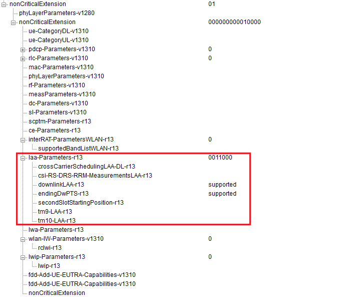
Band 46 is declared like any other band : the ringed entry carries bandEUTRA 46 and halfDuplex FALSE.It appears in a combination with band 4 : the ringed combination pairs band 46 with band 4, and band 4 is the licensed half.The band 46 half of that combination has no uplink : bandParametersUL-r10 is absent under it, and only bandParametersDL-r10 is filled in, at bandwidth class a and two layers.laa-Parameters-r13 reads 0011000 : seven optional fields sit under it, and the third and fourth are the ones present.Those two are downlinkLAA-r13 and endingDwPTS-r13 : both print supported, and the other five, secondSlotStartingPosition-r13 among them, are absent.
That last bitmap is worth pairing with the summary further up this page. The Small Cell Forum line says that a UE configured with the capability of initial partial subframe begins transmission in the second slot of the subframe. The capability that grants it is secondSlotStartingPosition-r13, and this UE does not have it.
36.213 clause 13A is where the two meet. The clause sets a condition on the higher layer parameter subframeStartPosition. When it indicates s07, a UE that detects PDCCH or EPDCCH starting in the second slot may assume the first slot is not occupied. A UE without the capability can only be given the other value, and the box in the next section shows it being given exactly that.
RRC Connection Recofngiruation - Adding LAA as a SCC
The box below decodes one RRC Connection Reconfiguration as a tree, with a presence flag on every optional field. Most of the reading is skipping the Omit lines. The author's red marks show the three places where LAA appears in this one.
RRC Connection Reconfiguration adding an LAA SCell, decoded as a tree,
+-rrcConnectionReconfiguration-r8 ::= SEQUENCE [000101]
  +-measConfig ::= SEQUENCE OPTIONAL:Omit
  +-mobilityControlInfo ::= SEQUENCE OPTIONAL:Omit
  +-dedicatedInfoNASList ::= SEQUENCE OF OPTIONAL:Omit
  +-radioResourceConfigDedicated ::= SEQUENCE [000000] OPTIONAL:Exist
  | +-srb-ToAddModList ::= SEQUENCE OF OPTIONAL:Omit
  | +-drb-ToAddModList ::= SEQUENCE OF OPTIONAL:Omit
  | +-drb-ToReleaseList ::= SEQUENCE OF OPTIONAL:Omit
  | +-mac-MainConfig ::= CHOICE OPTIONAL:Omit
  | +-sps-Config ::= SEQUENCE OPTIONAL:Omit
  | +-physicalConfigDedicated ::= SEQUENCE OPTIONAL:Omit
  | +-EXTENSION ::= SEQUENCE [00000]
  |   +-VERSION-BRACKETS1 ::= SEQUENCE OPTIONAL:Omit
  |   +-VERSION-BRACKETS2 ::= SEQUENCE OPTIONAL:Omit
  |   +-VERSION-BRACKETS3 ::= SEQUENCE OPTIONAL:Omit
  |   +-VERSION-BRACKETS4 ::= SEQUENCE OPTIONAL:Omit
  |   +-VERSION-BRACKETS5 ::= SEQUENCE OPTIONAL:Omit
  +-securityConfigHO ::= SEQUENCE OPTIONAL:Omit
  +-nonCriticalExtension ::= SEQUENCE [11] OPTIONAL:Exist
    +-lateNonCriticalExtension ::= OCTET STRING CONSTRAINTED [0000000101000000] OPTIONAL:Exist
    | +-RRCConnectionReconfiguration-v8m0-IEs ::= SEQUENCE [01]
    |   +-lateNonCriticalExtension ::= OCTET STRING OPTIONAL:Omit
    |   +-nonCriticalExtension ::= SEQUENCE [00] OPTIONAL:Exist
    |     +-antennaInfoDedicatedPCell-v10i0 ::= SEQUENCE OPTIONAL:Omit
    |     +-nonCriticalExtension ::= SEQUENCE OPTIONAL:Omit
    +-nonCriticalExtension ::= SEQUENCE [111] OPTIONAL:Exist
      +-otherConfig-r9 ::= SEQUENCE [0] OPTIONAL:Exist
      | +-reportProximityConfig-r9 ::= SEQUENCE OPTIONAL:Omit
      | +-EXTENSION ::= SEQUENCE [0]
      |   +-VERSION-BRACKETS1 ::= SEQUENCE OPTIONAL:Omit
      +-fullConfig-r9 ::= ENUMERATED [true] OPTIONAL:Exist
      +-nonCriticalExtension ::= SEQUENCE [010] OPTIONAL:Exist
        +-sCellToReleaseList-r10 ::= SEQUENCE OF OPTIONAL:Omit
        +-sCellToAddModList-r10 ::= SEQUENCE OF SIZE(1..maxSCell-r10[4]) [1] OPTIONAL:Exist
        | +-SCellToAddMod-r10 ::= SEQUENCE [101]
        |   +-sCellIndex-r10 ::= INTEGER (1..7) [1]
        |   +-cellIdentification-r10 ::= SEQUENCE OPTIONAL:Exist
        |   | +-physCellId-r10 ::= INTEGER (0..503) [1]
        |   | +-dl-CarrierFreq-r10 ::= INTEGER (0..maxEARFCN[65535]) [50665]
        |   +-radioResourceConfigCommonSCell-r10 ::= SEQUENCE OPTIONAL:Omit
        |   +-radioResourceConfigDedicatedSCell-r10 ::= SEQUENCE [1] OPTIONAL:Exist
        |   | +-physicalConfigDedicatedSCell-r10 ::= SEQUENCE [10] OPTIONAL:Exist
        |   | | +-nonUL-Configuration-r10 ::= SEQUENCE [0000] OPTIONAL:Exist
        |   | | | +-antennaInfo-r10 ::= SEQUENCE OPTIONAL:Omit
        |   | | | +-crossCarrierSchedulingConfig-r10 ::= SEQUENCE OPTIONAL:Omit
        |   | | | +-csi-RS-Config-r10 ::= SEQUENCE OPTIONAL:Omit
        |   | | | +-pdsch-ConfigDedicated-r10 ::= SEQUENCE OPTIONAL:Omit
        |   | | +-ul-Configuration-r10 ::= SEQUENCE OPTIONAL:Omit
        |   | | +-EXTENSION ::= SEQUENCE [00010]
        |   | |   +-VERSION-BRACKETS1 ::= SEQUENCE OPTIONAL:Omit
        |   | |   +-VERSION-BRACKETS2 ::= SEQUENCE OPTIONAL:Omit
        |   | |   +-VERSION-BRACKETS3 ::= SEQUENCE OPTIONAL:Omit
        |   | |   +-VERSION-BRACKETS4 ::= SEQUENCE [00000000000100] OPTIONAL:Exist
        |   | |   | +-pucch-Cell-r13 ::= ENUMERATED OPTIONAL:Omit
        |   | |   | +-pucch-SCell ::= CHOICE OPTIONAL:Omit
        |   | |   | +-crossCarrierSchedulingConfig-r13 ::= SEQUENCE OPTIONAL:Omit
        |   | |   | +-pdcch-ConfigSCell-r13 ::= SEQUENCE OPTIONAL:Omit
        |   | |   | +-cqi-ReportConfig-v1310 ::= SEQUENCE OPTIONAL:Omit
        |   | |   | +-pdsch-ConfigDedicated-v1310 ::= SEQUENCE OPTIONAL:Omit
        |   | |   | +-soundingRS-UL-ConfigDedicated-v1310 ::= CHOICE OPTIONAL:Omit
        |   | |   | +-soundingRS-UL-ConfigDedicatedUpPTsExt-r13 ::= CHOICE OPTIONAL:Omit
        |   | |   | +-soundingRS-UL-ConfigDedicatedAperiodic-v1310 ::= CHOICE OPTIONAL:Omit
        |   | |   | +-soundingRS-UL-ConfigDedicatedAperiodicUpPTsExt-r13 ::= CHOICE OPTIONAL:Omit
        |   | |   | +-csi-RS-Config-v1310 ::= SEQUENCE OPTIONAL:Omit
        |   | |   | +-laa-SCellConfiguration-r13 ::= SEQUENCE OPTIONAL:Exist
        |   | |   | | +-subframeStartPosition-r13 ::= ENUMERATED [s0]
        |   | |   | | +-laa-SCellSubframeConfig-r13 ::= BIT STRING SIZE(8) [00000000]
        |   | |   | +-csi-RS-ConfigNZPToAddModListExt-r13 ::= SEQUENCE OF OPTIONAL:Omit
        |   | |   | +-csi-RS-ConfigNZPToReleaseListExt-r13 ::= SEQUENCE OF OPTIONAL:Omit
        |   | |   +-VERSION-BRACKETS5 ::= SEQUENCE OPTIONAL:Omit
        |   | +-EXTENSION ::= SEQUENCE [000]
        |   |   +-VERSION-BRACKETS1 ::= SEQUENCE OPTIONAL:Omit
        |   |   +-VERSION-BRACKETS2 ::= SEQUENCE OPTIONAL:Omit
        |   |   +-VERSION-BRACKETS3 ::= SEQUENCE OPTIONAL:Omit
        |   +-EXTENSION ::= SEQUENCE [11]
        +-nonCriticalExtension ::= SEQUENCE OPTIONAL:Omit
The cell is identified twice over : physCellId-r10 reads 1 and dl-CarrierFreq-r10 reads 50665.That channel number falls inside band 46 : 36.101 Table 5.7.3-1 gives the band an offset of 46790 and a range running to 54539.It converts to 5537.5 MHz : 5150 plus a tenth of a megahertz for each of the 3875 channels above the offset.laa-SCellConfiguration-r13 is the LAA specific branch : it carries subframeStartPosition-r13 and laa-SCellSubframeConfig-r13, and nothing else.subframeStartPosition-r13 reads s0 : the other value, s07, is the one 36.213 clause 13A ties to a transmission starting in the second slot.
The capability and the configuration agree here. The capability message further up this page leaves secondSlotStartingPosition-r13 out, so this UE cannot be told to expect a burst that begins halfway through a subframe. The network sets subframeStartPosition-r13 to s0, which is the only value left.
A capability and a configuration can be read against each other : the missing capability and the s0 setting are one fact seen from two ends.Presence flags carry most of the information : almost every line reads OPTIONAL:Omit, and the few that read Exist are the message.The LAA branch sits deep in the tree : it arrives under a chain of nonCriticalExtension containers, which is how every field added after Release 8 reaches an RRC message.The decode was left exactly as captured : no value in it was checked against a specification or changed.
RRC Connection Recofngiruation - Measurement Configuration for LAA Cell
The second box is the same message type carrying a measurement configuration instead. What LAA adds here is a way to measure a cell that transmits only when it has won the channel, and the red marks sit on that part of the tree.
RRC Connection Reconfiguration carrying the measurement configuration for an LAA cell, decoded as a tree,
+-rrcConnectionReconfiguration-r8 ::= SEQUENCE [100000]
  +-measConfig ::= SEQUENCE [00000000000] OPTIONAL:Exist
  | +-measObjectToRemoveList ::= SEQUENCE OF OPTIONAL:Omit
  | +-measObjectToAddModList ::= SEQUENCE OF OPTIONAL:Omit
  | +-reportConfigToRemoveList ::= SEQUENCE OF OPTIONAL:Omit
  | +-reportConfigToAddModList ::= SEQUENCE OF OPTIONAL:Omit
  | +-measIdToRemoveList ::= SEQUENCE OF OPTIONAL:Omit
  | +-measIdToAddModList ::= SEQUENCE OF OPTIONAL:Omit
  | +-quantityConfig ::= SEQUENCE OPTIONAL:Omit
  | +-measGapConfig ::= CHOICE OPTIONAL:Omit
  | +-s-Measure ::= INTEGER OPTIONAL:Omit
  | +-preRegistrationInfoHRPD ::= SEQUENCE OPTIONAL:Omit
  | +-speedStatePars ::= CHOICE OPTIONAL:Omit
  | +-EXTENSION ::= SEQUENCE [1111]
  |   +-VERSION-BRACKETS1 ::= SEQUENCE [0] OPTIONAL:Exist
  |   | +-measObjectToAddModList-v9e0 ::= SEQUENCE OF OPTIONAL:Omit
  |   +-VERSION-BRACKETS2 ::= SEQUENCE [0] OPTIONAL:Exist
  |   | +-allowInterruptions-r11 ::= BOOLEAN OPTIONAL:Omit
  |   +-VERSION-BRACKETS3 ::= SEQUENCE [0000] OPTIONAL:Exist
  |   | +-measScaleFactor-r12 ::= CHOICE OPTIONAL:Omit
  |   | +-measIdToRemoveListExt-r12 ::= SEQUENCE OF OPTIONAL:Omit
  |   | +-measIdToAddModListExt-r12 ::= SEQUENCE OF OPTIONAL:Omit
  |   | +-measRSRQ-OnAllSymbols-r12 ::= BOOLEAN OPTIONAL:Omit
  |   +-VERSION-BRACKETS4 ::= SEQUENCE [0100] OPTIONAL:Exist
  |     +-measObjectToRemoveListExt-r13 ::= SEQUENCE OF OPTIONAL:Omit
  |     +-measObjectToAddModListExt-r13 ::= SEQUENCE OF SIZE(1..maxObjectId[32]) [1] OPTIONAL:Exist
  |     | +-MeasObjectToAddModExt-r13 ::= SEQUENCE
  |     |   +-measObjectId-r13 ::= INTEGER (maxObjectId-Plus1-r13[33]..maxObjectId-r13[64]) [33]
  |     |   +-measObject-r13 ::= CHOICE [measObjectEUTRA-r13]
  |     |     +-measObjectEUTRA-r13 ::= SEQUENCE [000000]
  |     |       +-carrierFreq ::= INTEGER (0..maxEARFCN[65535]) [0]
  |     |       +-allowedMeasBandwidth ::= ENUMERATED [mbw6]
  |     |       +-presenceAntennaPort1 ::= BOOLEAN [FALSE]
  |     |       +-neighCellConfig ::= BIT STRING SIZE(2) [00]
  |     |       +-offsetFreq ::= ENUMERATED OPTIONAL:Omit
  |     |       +-cellsToRemoveList ::= SEQUENCE OF OPTIONAL:Omit
  |     |       +-cellsToAddModList ::= SEQUENCE OF OPTIONAL:Omit
  |     |       +-blackCellsToRemoveList ::= SEQUENCE OF OPTIONAL:Omit
  |     |       +-blackCellsToAddModList ::= SEQUENCE OF OPTIONAL:Omit
  |     |       +-cellForWhichToReportCGI ::= INTEGER OPTIONAL:Omit
  |     |       +-EXTENSION ::= SEQUENCE [1111]
  |     |         +-VERSION-BRACKETS1 ::= SEQUENCE [00] OPTIONAL:Exist
  |     |         | +-measCycleSCell-r10 ::= ENUMERATED OPTIONAL:Omit
  |     |         | +-measSubframePatternConfigNeigh-r10 ::= CHOICE OPTIONAL:Omit
  |     |         +-VERSION-BRACKETS2 ::= SEQUENCE [0] OPTIONAL:Exist
  |     |         | +-widebandRSRQ-Meas-r11 ::= BOOLEAN OPTIONAL:Omit
  |     |         +-VERSION-BRACKETS3 ::= SEQUENCE [00001] OPTIONAL:Exist
  |     |         | +-altTTT-CellsToRemoveList-r12 ::= SEQUENCE OF OPTIONAL:Omit
  |     |         | +-altTTT-CellsToAddModList-r12 ::= SEQUENCE OF OPTIONAL:Omit
  |     |         | +-t312-r12 ::= CHOICE OPTIONAL:Omit
  |     |         | +-reducedMeasPerformance-r12 ::= BOOLEAN OPTIONAL:Omit
  |     |         | +-measDS-Config-r12 ::= CHOICE [setup] OPTIONAL:Exist
  |     |         |   +-setup ::= SEQUENCE [01]
  |     |         |     +-dmtc-PeriodOffset-r12 ::= CHOICE [ms40-r12]
  |     |         |     | +-ms40-r12 ::= INTEGER (0..39) [0]
  |     |         |     +-ds-OccasionDuration-r12 ::= CHOICE [durationFDD-r12]
  |     |         |     | +-durationFDD-r12 ::= INTEGER (1..maxDS-Duration-r12[5]) [1]
  |     |         |     +-measCSI-RS-ToRemoveList-r12 ::= SEQUENCE OF OPTIONAL:Omit
  |     |         |     +-measCSI-RS-ToAddModList-r12 ::= SEQUENCE OF SIZE(1..2[96])[1]
  |     |         |     | +-MeasCSI-RS-Config-r12 ::= SEQUENCE
  |     |         |     |   +-measCSI-RS-Id-r12 ::= INTEGER (1..maxCSI-RS-Meas-r12[96]) [1]
  |     |         |     |   +-physCellId-r12 ::= INTEGER (0..503) [0]
  |     |         |     |   +-scramblingIdentity-r12 ::= INTEGER (0..503) [0]
  |     |         |     |   +-resourceConfig-r12 ::= INTEGER (0..31) [0]
  |     |         |     |   +-subframeOffset-r12 ::= INTEGER (0..4) [0]
  |     |         |     |   +-csi-RS-IndividualOffset-r12 ::= ENUMERATED [dB-24]
  |     |         |     |   +-EXTENSION ::= SEQUENCE
  |     |         |     +-EXTENSION ::= SEQUENCE
  |     |         +-VERSION-BRACKETS4 ::= SEQUENCE [0000] OPTIONAL:Exist
  |     |           +-whiteCellsToRemoveList-r13 ::= SEQUENCE OF OPTIONAL:Omit
  |     |           +-whiteCellsToAddModList-r13 ::= SEQUENCE OF OPTIONAL:Omit
  |     |           +-rmtc-Config-r13 ::= CHOICE OPTIONAL:Omit
  |     |           +-carrierFreq-r13 ::= INTEGER OPTIONAL:Omit
  |     +-measIdToAddModList-v1310 ::= SEQUENCE OF OPTIONAL:Omit
  |     +-measIdToAddModListExt-v1310 ::= SEQUENCE OF OPTIONAL:Omit
  +-mobilityControlInfo ::= SEQUENCE OPTIONAL:Omit
  +-dedicatedInfoNASList ::= SEQUENCE OF OPTIONAL:Omit
  +-radioResourceConfigDedicated ::= SEQUENCE OPTIONAL:Omit
  +-securityConfigHO ::= SEQUENCE OPTIONAL:Omit
  +-nonCriticalExtension ::= SEQUENCE OPTIONAL:Omit
measDS-Config-r12 is the discovery signal measurement configuration : it arrives as a CHOICE set to setup.The measurement window repeats every 40 ms : dmtc-PeriodOffset-r12 takes the ms40-r12 branch, with an offset of 0.Each occasion is one subframe long : ds-OccasionDuration-r12 takes the durationFDD-r12 branch with the value 1.One CSI-RS resource is configured for it : measCSI-RS-Id 1, physCellId 0, scramblingIdentity 0, resourceConfig 0, subframeOffset 0, and an individual offset of dB-24.
37.213 explains why that configuration exists. Its clause 4.0 defines a discovery burst for an eNB. The burst carries the primary and secondary synchronisation signals and the cell-specific reference signals, and it may also carry non-zero power CSI reference signals. The measurement above is aimed at that burst.
Measuring such a cell is not like measuring a licensed one. It transmits only after winning the channel, so there is nothing regular to measure. The discovery burst supplies that regularity, and the 40 ms period in the box is the window the UE is told to look in.
A shared channel cell cannot transmit on demand : the discovery burst is what it sends so that the UE has something to measure.37.213 clause 4.0 lists what that burst holds : PSS, SSS and CRS for an eNB, and optionally non-zero power CSI-RS.The CSI-RS entry in the box matches that option : one resource, configured for measurement rather than for data.This box was also left as captured : the values in it are one network's settings.
Coexistance with WLAN - LBT and CSAT
Comparing to LTE, one of the most important design goal of LAA was how to make LAA better coexist with the exisiting WiFi communication. One of the measure was to use specially designed Frame Type (Frame Type 3). However, just employing the new frame type does not automatically solve the coexistance issues. There are several additional technologies that would be adopted for LAA-WiFi coexistance mainly in time domain scheduling perspective. I wrote a separate sections mainly for this topic. Refer to Time Domain Scheduling section in LTE-Unlicenced Overview page.
The listen before talk rules have moved. 36.213 clause 15 held them through the releases that introduced LAA, and in 36.213 v19.4.0 that clause reads Void. They sit in 37.213 now, Physical layer procedures for shared spectrum channel access, whose clause 4.1 opens by saying that an eNB operating LAA SCells shall perform the channel access procedures described there.
37.213 gives an eNB two procedures to choose between. A Type 1 procedure senses the channel for a defer duration and then counts down a random back-off drawn from a contention window, and a transmission carrying PDSCH has to use it. A Type 2 procedure senses for a short fixed time instead, and it is allowed for a discovery burst that carries no PDSCH.
The contention window and the length of the transmission that follows both depend on a channel access priority class. 37.213 Table 4.1.1-1 sets four of them.
|
37.213 Table 4.1.1-1 - Channel Access Priority Class for a downlink transmission |
||||
Priority class p |
mp |
CWmin,p |
CWmax,p |
Tmcot,p |
1 |
1 |
3 |
7 |
2 ms |
2 |
1 |
7 |
15 |
3 ms |
3 |
3 |
15 |
63 |
8 or 10 ms |
4 |
7 |
15 |
1023 |
8 or 10 ms |
The last column is the limit on one channel occupancy. Classes 3 and 4 are given as 8 or 10 ms. Which of the two applies depends on the channel. The specification asks whether the absence of any other technology sharing it can be guaranteed on a long term basis, for example by regulation.
The other half of this heading has no 3GPP answer. CSAT, carrier sense adaptive transmission, appears nowhere in 37.213 and nowhere in 36.213. It is a duty cycling scheme belonging to LTE-U rather than to LAA, which is the separation the overview page draws.
Listen before talk is specified in 37.213, not in 36.213 : clause 15 of 36.213 reads Void in v19.4.0.Type 1 is the random back-off procedure : a transmission that carries PDSCH has to use it.Type 2 is a short fixed sensing time : it is allowed for a discovery burst that carries no PDSCH.Four priority classes set the window and the burst length : class 1 gets 2 ms and a window of 3 to 7. Class 4 gets 8 or 10 ms and a window reaching 1023.CSAT is not a 3GPP mechanism : it appears in neither specification, and it belongs to LTE-U.
Reference
[1] Extending LTE to unlicensed spectrum globally – LAA (Qualcomm)
[2] 36.211 : 3GPP - E-UTRA; Physical channels and modulation, v19.3.0. Clause 4.3 gives frame structure type 3, and now allows the ten subframes of a radio frame to carry uplink as well as downlink.
[3] 36.213 : 3GPP - E-UTRA; Physical layer procedures, v19.4.0. Clause 13A gives the Subframe configuration for LAA field, Table 13A-1, the two PDCCH candidates for a CC-RNTI DCI, and the s07 start position. Clause 15, which held the channel access procedures, reads Void.
[4] 37.213 : 3GPP - Physical layer procedures for shared spectrum channel access, v19.0.0. Clause 4.0 defines the discovery burst, and clause 4.1 with Table 4.1.1-1 gives the downlink channel access procedures and the four priority classes.
[5] 36.101 : 3GPP - E-UTRA; User Equipment radio transmission and reception, v20.0.0. Table 5.5-1 gives bands 46 and 49 with their licensed-assisted notes, and Table 5.7.3-1 gives the channel numbers.