This will be on-going pages that never ends. I will update this page as I need to handle the specific test cases. You should refer to 3GPP 36.523-1 for the details. I will just put some summary and tips for each of the test cases defined in the LTE protocol conformance test specification.
To be honest, I don't think there are many people saying "3GPP document is easy to understand". One of the factors that makes the document vague/unclear is that it does not give you any practical examples as somebody mentioned in his blog. I totally agree with his opinion. But I think there is one place where you can get huge amount of examples related to each part of 3GPP documents. It is 'Conformance Test' specification (36-521 : RF Conformance, 36.521 : RRM, 36.523 : Protocol Conformance). So I think (hope) this page would help you not only for day-to-day conformance testing job, but also help you get practical understandings of other 3GPP documents. At least to me, LTE Protocol Conformance document is described in much clearer manner comparing to UMTS conformance document (34.123).
One of the questions that I got very frequently is "What am I supposed to study first ?", "Where do I have to start ?".
Unfortunately there would be no clear answer to these questions... but there can be a general guideline for this. My personal guide are
i) Don't try to look go through each test cases all over the test. Of course it is not a bad thing to know about each and every test cases, but you would give up very soon if you are trying to dig into the very details of each test cases.
ii) Go over the test case sections as often as possible and try to think of "what kind of test cases are there in this section ?", "what would be the generic procedure for this section ?". You don't have to read the test case description yet, just imagine that you are the person who is writing the test cases in 3GPP and design the test cases on your own. By this thought process, you will have to chance to apply what you know about each layers of LTE protocol stack. And you will also appreciate for those who put their effort to design all of these test cases in 3GPP -:). You will notice that designing a test cases is not an easy and trivial thing.
iii) Now you can get a little bit detail into each test case, but you don't have to go through all the test cases (it is alreay several hundred test cases are defined in 36.523). If you pick only one section that you are currently most familiar with and read all the test cases for the section, you would notice that most of the test procedure in that section is very similar to each other. Only a couple of parameter changes or a couple of additional steps. As far as I am experienced, almost always I could find one or two test cases that can represents overall test procedures for all the test cases in a specific section. Just pick those one or two test cases from each section and try to completely understand it. The test cases with star mark in this page is those that I picked as a representative test cases for a couple of sections. Of course this is based on my personal criteria and you would have different opinion. But no problem. You can pick whatever you think best represent the section.
Test Case Classification
The table below is a map rather than a reading list. Its value is in the shape of the numbering. The first digit tells you which layer or which state the test belongs to. That is enough to place any test case number you are handed, without looking it up.
Following is the list of sections from 36.523 V9.3.0 (2011-04). This is for the step ii) of the guideline described above.
|
Section |
Titles |
|
|
6 |
Idle mode operations |
|
|
6.1 |
In a pure E-UTRAN environment |
|
|
6.2 |
Multi-mode environment (E-UTRAN, UTRAN, GERAN,CDMA2000) |
|
|
6.3 |
Closed Subscriber Group cells |
|
|
6.4 |
Hybrid cells |
|
|
7 |
Layer 2 |
|
|
7.1 |
MAC |
|
|
7.2 |
RLC |
|
|
7.3 |
PDCP |
|
|
8 |
RRC |
|
|
8.1 |
RRC connection management procedures |
|
|
8.2 |
RRC connection reconfiguration |
|
|
8.3 |
Measurement configuration control and reporting |
|
|
8.4 |
Inter-RAT handover |
|
|
8.5 |
RRC others |
|
|
9 |
EPS mobility management |
|
|
9.1 |
EMM common procedures |
|
|
9.2 |
EMM specific procedures |
|
|
9.3 |
EMM connection management procedures (S1 mode only) |
|
|
9.4 |
NAS Security |
|
|
10 |
EPS session management |
|
|
10.2 |
Dedicated EPS bearer context activation |
|
|
10.3 |
EPS bearer context modification |
|
|
10.4 |
EPS bearer context deactivation |
|
|
10.5 |
UE requested PDN connectivity |
|
|
10.6 |
UE requested PDN disconnect |
|
|
10.7 |
UE requested bearer resource allocation |
|
|
10.8 |
UE requested bearer resource modification |
|
|
10.9 |
UE routing of uplink packets |
|
|
11 |
General tests |
|
|
11.1 |
SMS over SGs |
|
|
12 |
E-UTRA radio bearer tests |
|
|
12.1 |
General |
|
|
12.2 |
MIMO not configured |
|
|
12.3 |
MIMO configured |
|
|
13 |
Multi layer Procedures |
|
|
13.1 |
Call setup |
|
|
13.2 |
RRC connection reconfiguration |
|
|
13.3 |
||
|
13.4 |
Mobility |
|
|
14 |
ETWS |
|
|
14.1 |
ETWS reception in RRC_IDLE state / Duplicate detection |
|
|
14.2 |
ETWS reception in RRC_CONNECTED state / Duplicate detection |
|
|
14.3 |
ETWS reception in RRC_IDLE state / NITZ timestamp security check |
|
|
15 |
Mobility management based on DSMIPv6 (Dual-Stack Mobile IPv6) |
|
|
15.1 |
Discovery of the home agent via DNS |
|
|
15.2 |
Discovery of the Home Agent via DHCP |
|
|
15.3 |
Void |
|
|
15.4 |
Security association establishment with Home Agent reallocation procedure |
|
|
15.5 |
Security association establishment without home agent reallocation procedure |
|
|
15.6 |
Registration of a new IPv6 CoA (Binding Update/Acknowledgment procedure in IPv6 network) |
|
|
15.7 |
Registration of a new IPv4 CoA (Binding Update/Acknowledgment procedure in IPv4 network) |
|
|
15.8 |
Re-registration of IPv6 CoA |
|
|
15.9 |
Re-registration of IPv4 CoA |
|
|
15.10 |
Return to home link |
|
|
15.11 |
Dual-Stack Mobile IPv6 detach in IPv6 network |
|
|
15.12 |
Dual-Stack Mobile IPv6 detach in IPv4 network |
|
|
16 |
Home (e)NB related |
|
|
16.1 |
UE Idle Mode Operations |
|
|
17 |
MBMS in LTE |
|
|
17.1 |
MCCH Information Acquisition |
|
|
17.2 |
MBMS Data Reception |
|
|
17.3 |
MBMS Counting Procedure |
|
|
17.4 |
MBMS Service Continuity |
|
|
18 |
PWS |
|
|
18.1 |
CMAS on LTE |
|
The first digit places the test : 6 is idle mode, 7 is the layer 2 protocols, 8 is RRC and 9 is NAS.Section 6 splits on the radio access involved : 6.1 is a pure E-UTRAN environment and 6.2 is a multi-mode one.The numbering outlives the release : the table is from 36.523 V9.3.0, and the clause numbers for these areas have carried forward.Read the section titles before any test case : the titles say what the specification thinks is worth testing. That is the guideline step this table serves.
Activate Test Mode
A conformance test does nothing until the UE has been told it is being tested. That is what this message does, and it is the shorter of the two messages the section below pairs it with. It carries four information elements, one of which the specification then tells the UE to ignore.
The structure below is from 36.509 clause 6.5. The upper block is the information element table, and the two lower blocks expand the octets that the arrows point at.

Four mandatory elements and no optional ones. Two of them are half an octet each, so the whole message is four octets long.
The message is only ever sent downwards : 36.509 clause 6.5 says it goes SS to UE. The UE answers with ACTIVATE TEST MODE COMPLETE, defined in clause 6.6.Two elements share the first octet : Protocol discriminator and Skip indicator are half an octet each, and both point at 24.007 for their coding.The message type octet reads 1 0 0 0 0 1 0 0 : that is 0x84. It is what separates this message from CLOSE UE TEST LOOP.The UE test loop mode octet uses only its low bits : the rest are zero, and X2 with X1 pick the mode. 00 is mode A, 01 is mode B and 10 is mode C.That mode field does nothing here : the note under clause 6.5 says no specific UE action is currently specified on receiving it. The mode that matters is the one in the CLOSE UE TEST LOOP message.
The pairing with the loopback message is the part worth remembering. ACTIVATE TEST MODE puts the UE into test mode and nothing more. The loop itself is opened by CLOSE UE TEST LOOP and closed again by OPEN UE TEST LOOP. Test mode is left by DEACTIVATE TEST MODE in clause 6.7.
The mode field appears in both messages, and that is not a duplication to resolve. It is mandatory in both, and only the loopback message acts on it. Set it correctly here and wrongly there, and the tester still opens the wrong loop.
Test mode and the test loop are two separate things : this message turns on the first. The section below turns on the second.Four octets is the whole message : half an octet each for the discriminator and the skip indicator. Then one octet each for the type and the mode.0x84 against 0x80 : the message type is the only field that distinguishes the two messages.The mode field here is inert : set it, because it is mandatory, and do not expect the UE to act on it.
Test Loop Back
For conformance test, we have two major procedure to go through. One is "ACTIVATE TEST MODE" and the other one is "CLOSE UE TEST LOOP". In RF Conformance, only "ACTIVATE TEST MODE" would be enough, but in Protocol Conformance we have to go through both "ACTIVATE TEST MODE" and "CLOSE UE TEST LOOP". (For the details refer to TS 36.509 '5 Test Control (TC) protocol procedures and test loop operation').
|
Loopback Mode |
Description |
|
Mode A |
Simply put, this is the loopback made at the top of PDCP layer and this is Mandatory for all LTE UE. UE is supposed to loopback whatever PDCP SDU it gets from the network. It doesn't care about the contents or TFT etc. |
|
Mode B |
This is also a loopback sitting on top of PDCP layer, but unlike Mode A, in Mode B the loopback applies to a specific TFT associated with a specific EPS. This loopback can not be be used when more than one PDN connection is established or more than one primary PDP context is active. This is Mandatory for all LTE UE. |
|
Mode C |
Loopback Mode C is for E-MBMS testing. It provides counting of successfully received MBMS Packets on a given MTCH while UE is operating in E-MBMS/E-UTRA mode. This is mandatory only for the LTE UE supporting E-MBMS. |
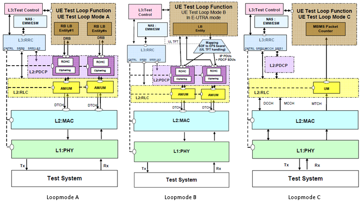
Overal function diagram for each test mode from TS 36.509 is as follows.
Three stacks, one question answered three ways: how far up the UE does the returned data travel before it is sent back.
All three stacks are the same below RLC : L2:MAC and L1:PHY are drawn identically. The Test System sits underneath with a Tx and an Rx arm.Mode A loops each radio bearer separately : the box at the top right holds RB LB Entity#1 through RB LB Entity#n. A DRB arrow runs from each one down into L2:PDCP.Mode B has a single LB Entity : beside it sits a box reading Mapping SDF to EPS bearer with UL TFT handling. The data it works on is labelled IP PDUs = PDCP SDUs.That labelling is the real difference : mode A returns whatever PDCP SDU arrives. Mode B has to look at the packet to decide which bearer it belongs to.Mode C does not loop anything : its box is an MBMS Packet Counter. The line from it runs straight past L2:PDCP rather than into it.The channel labels change with the mode : mode A and mode B show DTCH into MAC, and mode C shows DCCH, MCCH and MTCH. Its RLC entity is UM only.Test Control reaches the UE outside the loop : every stack has L3:Test Control at the top left, above NAS:EMM/ESM and L3:RRC. CNTRL, SRB0, SRB1 and SRB2 run between RRC and PDCP.
Message structure of CLOSE UE LOOPBACK is as follows. (For the details refer to TS 36.509 '5 Test Control (TC) protocol procedures and test loop operation').
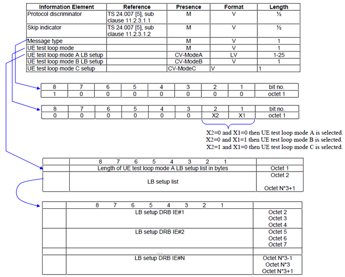
Three of the seven elements are conditional on the mode, so a real CLOSE UE TEST LOOP is shorter than this table looks.
The first four elements match ACTIVATE TEST MODE exactly : Protocol discriminator, Skip indicator, Message type and UE test loop mode. All four are mandatory and all four are format V.The message type octet reads 1 0 0 0 0 0 0 0 : 0x80, which is the value the worked example below uses.Only one setup element is ever present : the presence column reads CV-ModeA, CV-ModeB and CV-ModeC. Each is present only when the mode field selects it.Mode A is the only one with a list : its setup is format LV with a length of 1 to 25 octets. The mode B and mode C setups are a single octet each here.The list is counted in bytes, not in entries : octet 1 holds the length of the LB setup list in bytes. The entries start at octet 2.Each entry is three octets : the lower block numbers them 2 to 4, then 5 to 7, and the last one N*3-1 to N*3+1.
Check the drawing above against a current tester and one thing will be out of date. It is a screenshot of an older release, and the field has grown since. In 36.509 v17.4.0 the mode is carried in four bits rather than two. Modes A through I are defined, and the conditional setup elements run A, B, C, D, E, F and GH. Mode A, B and C keep the codings shown here, because the new bits were added above the old ones.
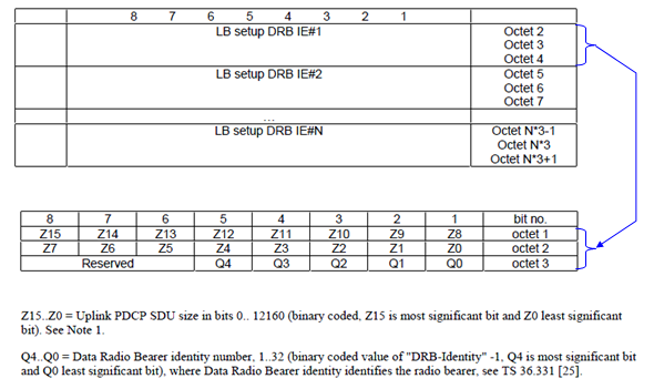
Two fields in three octets. The notes underneath the drawing make the third octet readable, and they are easy to skip.
The first two octets are one 16 bit number : Z15 down to Z0. The note gives it as the uplink PDCP SDU size in bits, from 0 to 12160.The third octet is mostly empty : its top three bits are marked Reserved, and only Q4 down to Q0 carry a value.Five bits hold the bearer identity : the note gives Q4 to Q0 as the data radio bearer identity number 1 to 32. It points at 36.331 for what DRB-Identity means.The coded value is the identity minus one : the note says so directly. 36.509 clause 6.1 puts the range at 0 to 31 representing DRB-Identity -1. A coded 0 means DRB-Identity 1.That offset is where this element gets misread : reading the octet as the bearer identity is off by one every time. The worked example below shows what it costs.
Let me give you an example for the message to help you understand the message structure.
HEX String : 0F 80 00 03 01 00 01
Analysis Result :
0 : Protocol discriminator
F : Skip indicator
80 : Message type (10000000)
00 : UE test loop mode (000000AB), where A=B=0 when Loopback mode is mode A
03 : Length of UE test loop mode A LB setup list in bytes
01 00 : Uplink PDCP SDU Size = 256 bits
01 : Data Radio Bearer ID = 2, because Q4..Q0 carries DRB-Identity minus one
The last octet of that string is worth one more look. Q4 down to Q0 read 00001, and the note under the drawing above codes them as the bearer identity minus one. So the bearer being looped is DRB-Identity 2, and an octet of 00 would have meant DRB-Identity 1.
The mode decides where the data reverses : above PDCP for A and B, and nowhere at all for C, which counts instead of returning.Mode A is the one to start with : it is mandatory for every UE. Nothing has to be configured beyond a bearer identity and a size.Mode B carries a restriction : it cannot be used with more than one PDN connection or more than one primary PDP context active.One setup element follows from the mode : pick the mode and the message shape follows from it. The other setup elements are conditional on the same field.The bearer identity in the setup is offset by one : one note under the octet drawing carries it. It is the easiest note on this page to miss.
Test Case Description
Following is the list of test cases that I have gone through for peronal needs. Those with the star mark is the ones that I personally think best represents the test cases for some sections. Of course, this list would extend as I get more and more involved in LTE test process.
I will start out this page with skeletones from 36.523-1 and keep adding comments as I gain more practical experiences for each of these items. (Number of stars put besides the test case shows the importance in terms of understanding a normal UE behavior and is the items that I want to recommend you to look into first and have through understanding. If you have clear understanding of those 'start' test case, it would be easier for you to understanding other test cases as well. Of course, this is totally my personal/subjective marking and I didn't take any survey of "thumb-up" or "thumb-down" -:) )
- 6.1.2.2 Cell selection / Qrxlevmin(
 )
) - 6.1.2.4 Cell reselection()
- 6.2.3.1 Inter-RAT cell reselection / From E-UTRA RRC_IDLE to GSM_Idle/GPRS Packet_Idle
- 7.1.1.2 DTCH or DCCH mapped to UL SCH/ DL-SCH / Reserved Logical Channel ID()
- 7.1.2.3 Correct selection of RACH parameters / Preamble selected by MAC itself / Contention based random access procedure
- 7.1.2.4 Random access procedure / Successful(
 )
) - 7.1.2.7 MAC contention resolution / Temporary C-RNTI ()
- 7.1.2.8 MAC contention resolution / C-RNTI
- 7.1.3.5 Correct HARQ process handling / CCCH
- 7.2.2.5.1 UM RLC / 5-bit SN / Correct use of sequence numbering()
- 8.1.1.6 RRC / BCCH modification in connected mode
- 8.1.2.3 RRC connection establishment / Return to idle state after T300 timeout
- 8.1.3.4 RRC connection release / Redirection to another E-UTRAN frequency
- 8.2.1.1 RRC connection reconfiguration / Radio bearer establishment for transition from RRC_IDLE to RRC_CONNECTED / Success / Default bearer / Early bearer establishment
- 8.2.1.3 RRC connection reconfiguration / Radio bearer establishment / Success /Dedicated bearer
- 8.2.4.2 RRC connection reconfiguration / Handover / Success / Common preamble()
- 8.3.3.1 Measurement configuration control and reporting / SON / ANR / CGI reporting of E-UTRAN cell
- 8.5.1.1 Radio link failure / RRC connection re-establishment success()
- 9.1.2.1 Authentication accepted
- 9.1.2.3 Authentication not accepted by the network / GUTI used / Authentication reject and re-authentication
 )
)
The stars are a reading order, not a difficulty rating : they mark the cases the author recommends starting from.Test cases repeat each other by design : most differ from a neighbour by a parameter or a step. One case per area therefore carries most of the value.The clause number is the index into 36.523-1 : every heading below keeps it, so any block here can be read beside the specification text.Several blocks quote a decoded message : those are captures from a live tester and are not corrected against the current release.
6.1.2.2 Cell selection / Qrxlevmin
Two power levels and one broadcast parameter decide this whole test. The UE is given a cell that fails the selection criterion, then the same cell is raised until it passes. The only question asked is whether the UE camped at the right moment. Everything below is there to fix those two levels precisely.
Test purpose of this test is simple. This test is to check if UE shows following rules properly or not
-
UE should not camp if the cell around it does not satisfy Cell Selection Criteria
-
UE should camp if the cell around it satisfy Cell Selection Criteria
You need to understand details of Cell Search (Detection) procedure, Cell Selection Procedure and Cell Selection Criteria to troubleshoot this test case or create similar test cases. This is much wider topic than you might think.
Test Conditions that you need to pay attention for this test case is as follows. You need to understand the meaning of each parameter and how those parameters influence Cell Selection process (See Cell Selection Criteria)

One cell, two moments. The parameters that go into the criterion are held still and only the power level moves.
Only one number changes between T1 and T2 : Cell-specific RS EPRE goes from -95 to -75 dBm/15kHz. Qrxlevmin, Qrxlevminoffset and Pcompensation are set once and left alone.Qrxlevmin is -84 dBm and the two offsets are zero : so the criterion reduces to the measured level against -84.At T1 the cell fails by 11 dB : -95 minus -84 is -11. The remark column says the level satisfies Srxlevcell 1 < 0 while still letting the UE read the PLMN identity.At T2 it passes by 9 dB : -75 minus -84 is +9, and the remark reads Srxlevcell 1 > 0.The T1 remark is the careful part : the cell has to be too weak to camp on and strong enough to decode. That is a narrower window than it first looks.The note points elsewhere for tolerance : downlink signal level uncertainty is specified in 36.508 section 4.3.4.1, not here.

The -84 dBm used above is not the broadcast value. This table shows what the cell actually sends.
One field is configured and the rest of the block is default : the table sets q-RxLevMin inside cellSelectionInfo and lists nothing else.The signalled value is -42 and the real one is -84 dBm : the Value/Remark column prints both, and the ratio between them is the 2 dB step the coding uses.That doubling is what links the two tables : -42 times 2 is -84, which is the Qrxlevmin the power level table assumes.The derivation path matters as much as the value : 36.508 clause 4.4.3.2 holds the default SIB1. The table only overrides one field of it.
Overall protocol sequence is as follows :
|
Step |
Direction |
Message |
Memo |
|
1 |
SS |
Set the cell power and SIB parameters as "T1" in table 6.1.2.2.3.2-1. |
|
|
2 |
UE |
Turn on UE |
|
|
3 |
UE ---> SS |
RRC: RRCConnectionRequest |
If UE sends this message, it means "FAIL" since T1 does not meet Cell Selection Criteria |
|
4 |
SS |
Set the cell power and SIB parameters as "T2" in table 6.1.2.2.3.2-1. |
|
|
5 |
UE ---> SS |
RRC: RRCConnectionRequest |
If UE sends this message, it means "PASS" since T2 meet Cell Selection Criteria |
|
6 |
UE <---> SS |
< Complete Registration Sequence > |
|
6.1.2.4 Cell reselection
Simply put, this test case is to check if UE changes it's serving cell from a cell to another cell when it sees a cell with better signal which meets cell reselection criteria.
In terms of test procedure and protocol sequence may look simple for this case, but in terms of UE operation this may be one of the most complicated procedure. A lot of network parameter (Various SIB parameters) and UE side factors (Cell Evaluation algorithm) are involved in this test procedure. So you need to have very good understanding on Idle Mode Procedure to expand and troubleshoot this test.
Try to understand the details on parameters/factors in Idle Mode procedure and you can create a lot of additional test cases just by changing those parameters and power of Cell1 and Cell2.
Test Condition is as follows.

Two tables in one screenshot. The upper one sets the radio condition and the lower one is the entire test.
Reselection needs two cells, so there are two columns : at T1 cell 1 is -85 and cell 2 is -79 dBm/15kHz.Six dB is the whole stimulus : the remark says the levels are assigned to satisfy Rcell 1 < Rcell 2. That is the ranking the UE reselects on.The main behaviour table has two steps and only one of them acts : step 1 changes the cell 2 level. Step 2 is a check with nothing sent.Step 2 carries the only test purpose : its TP column reads 1, and its message columns are dashes on both sides.The check is delegated : it asks whether the generic test procedure in 36.508 subclause 6.4.2.7 shows the UE camped on cell 2.
As you see, the required protocol sequence is defined in 36.508, not in 36.523.
|
Step |
Direction |
Message |
Memo |
|
Make it sure that Cell 1 and Cell 2 has
|
|||
|
1 |
UE <---> SS |
Registration to Cell 1 |
|
|
2 |
UE <---> SS |
< Idle in Cell 1 > |
|
|
3 |
UE <---> SS |
Change cell power so that Cell 2 has bettern signal than Cell 1 |
|
|
4 |
UE ---> SS |
RRC: RRCConnectionRequest |
|
|
5 |
UE <--- SS |
RRC: RRCConnectionSetup |
|
|
6 |
UE ---> SS |
RRC: RRCConnectionSetupComplete NAS: TRACKING AREA UPDATE REQUEST |
|
|
7 |
UE <--- SS |
RRC: DLInformationTransfer NAS: TRACKING AREA UPDATE ACCEPT |
|
|
8 |
UE <--- SS |
RRC: RRCConnectionReconfiguration + NAS: ATTACH ACCEPT NAS: ACTIVATE DEFAULT EPS BEARER CONTEXT REQUEST |
|
|
9 |
UE ---> SS |
RRC: ULInformationTransfer NAS: TRACKING AREA UPDATE COMPLETE |
PASS/FAIL |
|
10 |
UE <--- SS |
RRC: RRCConnectionRelease |
|
Note 1 : TAI for Cell 1 and Cell 2 are different.
Note 2 : The periodic tracking area updating timer T3412 is deactivated by default during the attach procedure (TS 36.508 clause 4.7.2).
Note 3 : The SS does not initiate authentication and NAS SECURITY MODE COMMAND are not performed (reuse of keys allocated during the attach procedure).
6.2.3.1 Inter-RAT cell reselection / From E-UTRA RRC_IDLE to GSM_Idle/GPRS Packet_Idle
Simply put, this test case is to check if UE changes it's serving cell from a cell to another non-LTE cell(GSM/GPRS Cell) when it sees a cell with better signal which meets cell reselection criteria.
The factors to be specificially noticed is about the priority based reselection. So you need to get familiar to Cell Reselection Criteria based on Priority in addition to general Idle mode procedure.
Major Sub Test under this test can be summarized as follows.
-
Sub Test 1 : From LTE Cell (E-UTRA) to Higher Priority GERAN
-
Sub Test 2 : From LTE Cell (E-UTRA) to Lower Priority GERAN
Test Condition is as follows.

Three moments on the serving cell. The Srxlev row is what the UE works out for itself, and it is tabulated so the reader can check the intent.
Three time instances move one cell : Cell-specific RS EPRE reads -70 at T1, -60 at T2 and -100 dBm/15kHz at T3.The Srxlev row makes the offsets visible : 36 at T1 and 46 at T2. So the sum subtracted from the measured level is -106 dBm throughout.T3 is the moment the test depends on : -100 against that same -106 leaves 6 dB. The remark reads Srxlevcell 1 < 20, with threshServingLow named beside it.T1 sets up a comparison rather than a threshold : its remark is Srxlevcell 1 > Srxlevcell 24 > 0. The serving cell has to stay the better of the two.The note says where the number comes from : Srxlev is calculated in the UE. The tabulated value is the expected result, not something the tester sets.

The GERAN side of the same three moments. One cell is switched off as the other is switched on, which is how the test forces a choice.
The parameter changes with the radio access : these rows carry RF Signal Level in dBm and C1 in dB. The E-UTRA table used RS EPRE and Srxlev.At T1 only cell 24 is on : -80 dBm with a C1 of 21 dB, and cell 25 reads OFF.At T3 the pair has swapped : cell 24 is OFF and cell 25 is at -80 dBm.Each live cell is given its own threshold : the T1 remark names threshX-High against cell 24. The T3 remark names threshX-Low against cell 25.The note repeats the point from the table above : C1 is calculated in the UE, so the dB figures are expectations rather than settings.

This is the threshold the power table compared against, as the cell broadcasts it. The 2 dB coding appears again.
Three fields inside cellReselectionServingFreqInfo : s-NonIntraSearch, threshServingLow and cellReselectionPriority.threshServingLow is signalled as 10 and means 20 dB : the comment column prints the actual value. It is the same 2 dB step q-RxLevMin uses.That 20 dB is the last number the chain needed : the power table put Srxlev at 6 dB at T3. Six is below 20, so the UE starts looking at the other radio access.s-NonIntraSearch is Not present : the cell broadcasts no such threshold. The UE never gets a level above which it may stop searching other frequencies.cellReselectionPriority is 4 for no particular reason : the comment says a middle value in the range has been selected. That is the specification saying the exact number does not matter here.
|
Step |
Direction |
Message |
Memo |
|
1 |
UE <---> SS |
Registration to Cell 1 (EUTRA) |
|
|
2 |
UE <---> SS |
< Idle in Cell 1 (EUTRA)> |
|
|
3 |
SS |
Change Cell Power as T1 (EUTRA Cell Power is lower than GERAN) |
Condition for Reselect from Low Priority to High Priority |
|
4 |
UE <---> SS |
UE Camp on to GERAN(Cell 24) and perform RAU |
Test Passes if UE camp on to GERAN Cell |
|
5 |
UE <---> SS |
< Idle in Cell 24(GERAN) for at least 5 seconds > |
|
|
6 |
SS |
Change Cell Power as T2 (All GERAN is OFF, only EUTRA is ON) |
|
|
7 |
UE <---> SS |
Camps to Cell 1 (EUTRA) |
|
|
8 |
UE <---> SS |
< Idle in Cell 1(EUTRA) for at least 5 seconds > |
|
|
9 |
SS |
Change Cell Power as T3 (EUTRA Cell Power is lower than GERAN) |
Condition for Reselect from High Priority to Low Priority |
|
10 |
UE ---> SS |
UE Camp on to GERAN(Cell 25) |
Test Passes if UE camp on to GERAN Cell |
7.1.1.2 DTCH or DCCH mapped to UL SCH/ DL-SCH / Reserved Logical Channel ID
Simply put, this test case is to check if UE decode LCID field of Downlink MAC PDU and act properly according to the LCID. More specifically this TC test UE response to Reserved LCID and LCID for "Identity of the logical channel" in the following table.

Seven rows, and this test case is about the third one. Everything the UE must discard is in that single range.
The field is five bits, so there are 32 values to account for : the table spends them in seven rows.00000 is CCCH : the channel the UE uses before it has a dedicated bearer.00001 to 01010 identify a logical channel : ten values, so DTCH and DCCH identities land in 1 to 10.01011 to 11011 is Reserved : that is 11 to 27 in decimal, and it is the range this test case sends.The top four values are MAC control elements : 11100 is UE Contention Resolution Identity and 11101 is Timing Advance Command. 11110 is DRX Command and 11111 is Padding.Reserved sits between the two useful blocks : a UE that reads the field loosely will treat a reserved value as one of its neighbours. That is the mistake the test is built to find.
TP1 : This tests if UE act in the following manner or not.
i) < UE is in RRC connected state with DRB with LCID = 3 >
ii) SS send MAC PDU with reserved LCID (T-CRNTI is properly set for the UE)
iii) UE decode the MAC PDU but should discard it since LCID is reserved.
TP2 : This tests if UE act in the following manner or not.
i) < UE is in RRC connected state with DRB with LCID = 3 >
ii) SS send MAC PDU with LCID = '00011'B (T-CRNTI is properly set for the UE)
iii) UE decode the MAC PDU and transfer it to higher layer properly.
|
Step |
Direction |
Message |
Memo |
|
1 |
UE <---> SS |
< RRC Connection Setup > |
|
|
2 |
UE <---> SS |
< Authentication > |
|
|
3 |
UE <---> SS |
< Security Mode > |
|
|
4 |
UE <---> SS |
< ESM : Information > |
|
|
5 |
UE <--- SS |
RRC: DLInformationTransfer + TC: ACTIVATE TEST MODE |
|
|
6 |
UE ---> SS |
RRC: ULInformationTransfer + TC: ACTIVATE TEST MODE COMPLETE |
|
|
7 |
UE <---> SS |
< RRC : Security > |
|
|
8 |
UE <---> SS |
< RRC: UECapabilityEnquiry > |
|
|
9 |
UE <--- SS |
RRC: RRCConnectionReconfiguration + NAS: ATTACH ACCEPT NAS: ACTIVATE DEFAULT EPS BEARER CONTEXT REQUEST |
DRB, LCID = 00011 |
|
10 |
UE ---> SS |
RRC: RRCConnectionReconfigurationComplete |
|
|
11 |
UE ---> SS |
RRC: ULInformationTransfer + NAS: ATTACH COMPLETE NAS: ACTIVATE DEFAULT EPS BEARER CONTEXT ACCEPT |
|
|
12 |
UE <--- SS |
RRC: DLInformationTransfer + TC: CLOSE UE TEST LOOP |
|
|
13 |
UE ---> SS |
RRC: ULInformationTransfer + TC: CLOSE UE TEST LOOP COMPLETE |
|
|
14 |
UE <--- SS |
MAC PDU with reserved LCID |
|
|
15 |
UE ---> SS |
UE should not send any SR within 5 seconds |
PASS/FAIL |
|
16 |
UE <--- SS |
MAC PDU with valid LCID(00011) |
|
|
17 |
UE ---> SS |
UE should transmit SR |
PASS/FAIL |
|
18 |
UE <--- SS |
UL Grant |
|
|
19 |
UE ---> SS |
UE should send MAC PDU with LCID 00011 |
PASS/FAIL |
7.1.2.3 Correct selection of RACH parameters / Preamble selected by MAC itself / Contention based random access procedure
This test case is similar to 7.1.2.3, but 7.1.2.3 is focused more on overall RACH procedure whereas this test case is focused more on detailed parameters involved in the RACH procedure.
TP1 : This tests if UE act in the following manner or not.
i) < Now in Idle Mode >
ii) SS send Paging message (MAC PDU carrying the CCCH is less than messageSizeGroupA)
Note : messageSizeGroupA is specified in SIB2 as follows. (This is just an example and it may not match the value in the conformance test case)
An excerpt of a decoded SIB2, quoted as the author captured it. The tree starts part way down, and nothing in it has been corrected against a specification.
            |     | +-rach-ConfigCommon ::= SEQUENCE
            |     | | +-preambleInfo ::= SEQUENCE [1]
            |     | | | +-numberOfRA-Preambles ::= ENUMERATED [n52]
            |     | | | +-preamblesGroupAConfig ::= SEQUENCE OPTIONAL:Exist
            |     | | |   +-sizeOfRA-PreamblesGroupA ::= ENUMERATED [n4]
            |     | | |   +-messageSizeGroupA ::= ENUMERATED [b56]
            |     | | |   +-messagePowerOffsetGroupB ::= ENUMERATED [minusinfinity]
TP2 : This tests if UE act in the following manner or not.
i) < Now in Idle State >
ii) SS send Paging
iii) UE send PRACH in response to Paging
iv) SS send RAR (RACH Response).
v) UE send RRC Connection Request
vi) SS does not send 'Contention Resolution' within a certain time span (contentionResolutionTimer)
vii) UE Retransmit PRACH
An excerpt of a decoded SIB2 rach-Config, quoted as the author captured it. It records one broadcast rather than specification text, so none of its values have been corrected.
            |     | +-rach-Config ::= SEQUENCE
            |     | | +-preambleInfo ::= SEQUENCE [0]
            |     | | | +-numberOfRA-Preambles ::= ENUMERATED [n52]
            |     | | | +-preamblesGroupAConfig ::= SEQUENCE OPTIONAL:Omit
            |     | | +-powerRampingParameters ::= SEQUENCE
            |     | | | +-powerRampingStep ::= ENUMERATED [dB2]
            |     | | | +-preambleInitialReceivedTargetPower ::= ENUMERATED [dBm-104]
            |     | | +-ra-SupervisionInfo ::= SEQUENCE
            |     | | | +-preambleTransMax ::= ENUMERATED [n6]
            |     | | | +-ra-ResponseWindowSize ::= ENUMERATED [sf10]
            |     | | | +-mac-ContentionResolutionTimer ::= ENUMERATED [sf48]
            |     | | +-maxHARQ-Msg3Tx ::= INTEGER (1..8) [4]
TP3 : This tests if UE act in the following manner or not. (The description for this TP in 36.523 is a little bit confusing to me for now. I will just put down as described in the specification and clarify further later).
i) < Now in Idle State >
ii) SS send Paging
iii) UE send PRACH in response to Paging
iv) SS send RAR (RACH Response).
v) UE send RRC Connection Request
vi) SS does not send 'Contention Resolution' within a certain time span (contentionResolutionTimer) after more than preambleTransMax transmission from UE.
vii) UE retransmit PRACH using the a preamble in the same group of random access preambles as used for the first transmission of Msg3
TP4 : This tests if UE act in the following manner or not.
i) < Now in Idle State >
ii) Now UE has some data to transmit and the size of data (MAC PDU size) is greater than messageSizeGroupA.
iii) UE transmit PRACH using using a preamble in group B of random access preambles indicated in SIB2
7.1.2.4 Random access procedure / Successful
Whether you are doing the testing job or you just want to study about LTE, I want to recommend you to take this test case as a backbone (framework) test case for all RACH process.
This test case tests the most basic behavior (requirement) of RACH process and test the following three behavior (I waill call this expected behavior as 'TP'(Test Purpose) as in 3GPP 36.523).
TP1 : This tests if UE act in the following manner or not. (The most basic RACH Test)
i) < Now in Idle State >
ii) SS send Paging
iii) UE send PRACH in response to Paging
TP2 : This tests if UE act in the following manner or not.
i) < Now in Idle State >
ii) SS send Paging
iii) UE send PRACH in response to Paging
iv) SS does not send RAR(RACH Response) within a certain time period (ra-ResponseWindowSize).
v) UE resend PRACH
Note : ra-ResponseWindowSize is informed to UE by SIB2 as follows. (This is just example. The value specified in this example may differ from the value specified in this conformance test case.)
An excerpt of a decoded SIB2 rach-Config, quoted as the author captured it. It records one broadcast rather than specification text, so none of its values have been corrected.
            |     | +-rach-Config ::= SEQUENCE
            |     | | +-preambleInfo ::= SEQUENCE [0]
            |     | | | +-numberOfRA-Preambles ::= ENUMERATED [n52]
            |     | | | +-preamblesGroupAConfig ::= SEQUENCE OPTIONAL:Omit
            |     | | +-powerRampingParameters ::= SEQUENCE
            |     | | | +-powerRampingStep ::= ENUMERATED [dB2]
            |     | | | +-preambleInitialReceivedTargetPower ::= ENUMERATED [dBm-104]
            |     | | +-ra-SupervisionInfo ::= SEQUENCE
            |     | | | +-preambleTransMax ::= ENUMERATED [n6]
            |     | | | +-ra-ResponseWindowSize ::= ENUMERATED [sf10]
            |     | | | +-mac-ContentionResolutionTimer ::= ENUMERATED [sf48]
            |     | | +-maxHARQ-Msg3Tx ::= INTEGER (1..8) [4]
TP3 : This tests if UE act in the following manner or not.
i) < Now in Idle State >
ii) SS send Paging
iii) UE send PRACH in response to Paging
iv) SS send RAR (RACH Response).
v) UE send RRC Connection Request
vi) SS does not send 'Contention Resolution'. (SS does not send any response)
vii) UE Retransmit PRACH
7.1.2.7 MAC contention resolution / Temporary C-RNTI
This is the test case to check about 'Contention Resolution' step in RACH process. It has several subtests as described below. This test would give you pretty clear understanding of mechanism of 'Contention Resolution' step.
TP1 : This tests if UE act in the following manner or not.
i) < Now in Idle State >
ii) SS send Paging
iii) UE send PRACH in response to Paging
iv) SS send RAR (RACH Response).
v) UE send RRC Connection Request
vi) SS does not sends any MAC PDU including 'Contention Resolution' MAC PDU within a certain time frame (Contention Resolution Timer).
vii) UE send 'RRC Connection Request' again.
Note : ra-ResponseWindowSize is informed to UE by SIB2 as follows. (This is just example. The value specified in this example may differ from the value specified in this conformance test case.)
An excerpt of a decoded SIB2 rach-Config, quoted as the author captured it. It records one broadcast rather than specification text, so none of its values have been corrected.
            |     | +-rach-Config ::= SEQUENCE
            |     | | +-preambleInfo ::= SEQUENCE [0]
            |     | | | +-numberOfRA-Preambles ::= ENUMERATED [n52]
            |     | | | +-preamblesGroupAConfig ::= SEQUENCE OPTIONAL:Omit
            |     | | +-powerRampingParameters ::= SEQUENCE
            |     | | | +-powerRampingStep ::= ENUMERATED [dB2]
            |     | | | +-preambleInitialReceivedTargetPower ::= ENUMERATED [dBm-104]
            |     | | +-ra-SupervisionInfo ::= SEQUENCE
            |     | | | +-preambleTransMax ::= ENUMERATED [n6]
            |     | | | +-ra-ResponseWindowSize ::= ENUMERATED [sf10]
            |     | | | +-mac-ContentionResolutionTimer ::= ENUMERATED [sf48]
            |     | | +-maxHARQ-Msg3Tx ::= INTEGER (1..8) [4]
TP2 : This tests if UE act in the following manner or not.
i) < Now in Idle State >
ii) SS send Paging
iii) UE send PRACH in response to Paging
iv) SS send RAR (RACH Response).
v) UE send RRC Connection Request
vi) SS sends RRC Connection Setup message, but this does not include 'Contention Resolution' MAC PDU.
vii) UE send 'RRC Connection Request' again.
TP3 : This tests if UE act in the following manner or not.
i) < Now in Idle State >
ii) SS send Paging
iii) UE send PRACH in response to Paging
iv) SS send RAR (RACH Response).
v) UE send RRC Connection Request
vi) SS sends RRC Connection Setup message and it includes 'Contention Resolution' MAC PDU, but the contention resolution identity does not match the UE id.
vii) UE send 'RRC Connection Request' again.
TP4 : This tests if UE act in the following manner or not.(This shows what should happen if there is no problem with 'Contention Resolution' step)
i) < Now in Idle State >
ii) SS send Paging
iii) UE send PRACH in response to Paging
iv) SS send RAR (RACH Response).
v) UE send RRC Connection Request
vi) SS sends RRC Connection Setup message and it includes 'Contention Resolution' MAC PDU, and the contention resolution Indentity is also correct one.
vii) UE send 'RRC Connection Setup Complete'.
7.1.2.8 MAC contention resolution / C-RNTI
This is test for the contention resolution step during RACH process happending in Handover process. (you should notice that RACH process is a critical part in handover process in LTE. UMTS handover process does not go through RACH process during the handover).
TP1 : This tests if UE act in the following manner or not.
i) < Configure Two Cells in SS >
ii) < Now in Idle State : Cell 1 >
ii) SS send Paging
iii) < Establish RRC Connection and Complete 'RRC Connection Reconfiguration' for activating data bearer >
iv) < SS increase the power of the second cell so that UE can perform the handover to the second cell >
v) SS send "RRC Connection Reconfiguration (for Handover)" and this message does not include any explicit Random Access Preamble configuration.
vi) UE send 'RRC Connection Reconfiguration Complete' to SS Cell2.
vii) SS does not schedule any PDCCH transmission with UE C-RNTI.
viii) UE resend 'RRC Connection Reconfiguration Complete'
TP2 : This tests if UE act in the following manner or not.
i) < Configure Two Cells in SS >
ii) < Now in Idle State : Cell 1 >
ii) SS send Paging
iii) < Establish RRC Connection and Complete 'RRC Connection Reconfiguration' for activating data bearer >
iv) < SS increase the power of the second cell so that UE can perform the handover to the second cell >
v) SS send "RRC Connection Reconfiguration (for Handover)" and this message does not include any explicit Random Access Preamble configuration.
vi) UE send 'RRC Connection Reconfiguration Complete' to SS Cell2.
vii) SS does sends PDCCH transmission with UE C-RNTI.
viii) UE should not resend 'RRC Connection Reconfiguration Complete'
7.1.3.5 Correct HARQ process handling / CCCH
This one is about silence rather than about messages. Each of the four test purposes below ends with the UE sending no HARQ feedback, or sending only one of the two. So the thing being checked is what the UE declines to acknowledge during random access. That makes it awkward to instrument, which is the point the notes underneath raise.
Note : This TC looks a little confusing to me.. I may need further investigation for clarification.
Note : It would be not easy to implement this on the test system since it has to check HARQ ACK/NACK on real time.
This is to check whether UE send HARQ ACK or NACK properly in response to the message from the network (RAR, CR).
This test case test the following check points (TP : Test Purpose).
TP 1 : This is to check the following two behavior.
i) UE send 'PRACH'
ii) SS send RAR with RA-RNTI
iii) UE should not send any ACK or NACK for RAR.
TP 2 : This is to check the following two behavior.
i) UE send 'PRACH'
ii) SS send RAR with RA-RNTI
iii) UE send 'Msg3 (RRC Connection Request)'
iv) SS send RRC Connection Setup and Contention Resolution with wrong UE ID, addressed to T-CRNTI
v) UE should not send any ACK or NACK
TP 3 : This is to check the following two behavior.
i) UE send 'PRACH'
ii) SS send RAR with RA-RNTI
iii) UE send 'Msg3 (RRC Connection Request)'
iv) SS send RRC Connection Setup and Contention Resolution with right UE ID, addressed to T-CRNTI with wrong CRC
v) UE should not send NACK
TP 4 : This is to check the following two behavior.
i) UE send 'PRACH'
ii) SS send RAR with RA-RNTI
iii) UE send 'Msg3 (RRC Connection Request)'
iv) SS send RRC Connection Setup and Contention Resolution with right UE ID, addressed to T-CRNTI with right CRC
v) UE should not send ACK
|
Step |
Direction |
Message |
Memo |
|
1 |
UE <---> SS |
< Power On and Registration > |
Assign a S-TMSI |
|
2 |
UE <---> SS |
< Now UE is in IDLE mode > |
|
|
3 |
UE <--- SS |
Paging with incorrect UE ID |
|
|
4 |
UE ---> SS |
Wait for 5 secs (UE should not respond to Paging during this period) |
PASS/FAIL |
|
5 |
UE <--- SS |
Paging with incorrect UE ID |
|
|
6 |
UE ---> SS |
PRACH |
|
|
7 |
UE <--- SS |
RAR including T-CRNTI with wrong CRC |
|
|
8 |
UE ---> SS |
UE should not send any HARQ ACK/NACK |
PASS/FAIL |
|
9 |
UE ---> SS |
PRACH |
|
|
10 |
UE <--- SS |
RAR including T-CRNTI |
|
|
11 |
UE ---> SS |
RRC Connection Request |
|
|
12 |
UE <--- SS |
CR with wrong UE ID + RRC Connection Setup |
|
|
13 |
UE ---> SS |
UE should not send any HARQ ACK/NACK |
PASS/FAIL |
|
14 |
UE ---> SS |
PRACH |
|
|
15 |
UE <--- SS |
RAR including T-CRNTI |
|
|
16 |
UE ---> SS |
RRC Connection Request |
|
|
17 |
UE <--- SS |
(CR with proper UE ID + RRC Connection Setup) with wrong CRC |
|
|
18 |
UE ---> SS |
UE should not send any HARQ NACK |
PASS/FAIL |
|
19 |
UE ---> SS |
PRACH |
|
|
20 |
UE <--- SS |
RAR including T-CRNTI |
|
|
21 |
UE ---> SS |
RRC Connection Request |
|
|
22 |
UE <--- SS |
(CR with proper UE ID + RRC Connection Setup) with right CRC |
|
|
23 |
UE ---> SS |
UE should send any HARQ ACK |
PASS/FAIL |
7.2.2.5.1 UM RLC / 5-bit SN / Correct use of sequence numbering
The sequence number field here is five bits wide, so it counts to 31 and then starts again. All three test purposes below are built on that one fact, and the third is the only one that reaches the wrap. A framework test like this one is worth reading before any other RLC case.
This test case test basic operation of UM RLC, so it can be a framework for UM RLC.
TP 1: This is to check the following two behavior.
i) UE is in RRC_CONNECTED mode
ii) UE transmit the first PDU and the SN for the PDU is 0
TP 2 : This is to check the following two behavior.
i) UE is in RRC_CONNECTED mode
ii) UE transmit the first PDU and the SN for the PDU is 0
iii) UE transmit the next PDU and the SN for the PDU is incremented by 1
TP 3 : This is to check the following two behavior.
i) UE is in RRC_CONNECTED mode
ii) UE transmit the first PDU and the SN for the PDU is 0
iii) UE transmit the next PDU and the SN for the PDU is incremented by 1
iv) UE transmit more than 32 PDUs and the SN should be wrapped around after transmitting 32 PDUs
|
Step |
Direction |
Message |
Memo |
|
1 |
UE <---> SS |
< RRC Connection Setup > |
|
|
2 |
UE <---> SS |
< Authentication > |
|
|
3 |
UE <---> SS |
< Security Mode > |
|
|
4 |
UE <---> SS |
< ESM : Information > |
|
|
5 |
UE <--- SS |
RRC: DLInformationTransfer + TC: ACTIVATE TEST MODE |
|
|
6 |
UE ---> SS |
RRC: ULInformationTransfer + TC: ACTIVATE TEST MODE COMPLETE |
|
|
7 |
UE <---> SS |
< RRC : Security > |
|
|
8 |
UE <---> SS |
< RRC: UECapabilityEnquiry > |
|
|
9 |
UE <--- SS |
RRC: RRCConnectionReconfiguration + NAS: ATTACH ACCEPT NAS: ACTIVATE DEFAULT EPS BEARER CONTEXT REQUEST |
|
|
10 |
UE ---> SS |
RRC: RRCConnectionReconfigurationComplete |
|
|
11 |
UE ---> SS |
RRC: ULInformationTransfer + NAS: ATTACH COMPLETE NAS: ACTIVATE DEFAULT EPS BEARER CONTEXT ACCEPT |
|
|
12 |
UE <--- SS |
RRC: DLInformationTransfer + TC: CLOSE UE TEST LOOP |
|
|
13 |
UE ---> SS |
RRC: ULInformationTransfer + TC: CLOSE UE TEST LOOP COMPLETE |
|
|
14 |
UE <--- SS |
RLC UMD PDU with SN = 0 |
|
|
15 |
UE ---> SS |
UE should transmit RLC UMD PDU with SN = 0 |
PASS/FAIL |
|
16 |
UE <--- SS |
RLC UMD PDU with SN incremented by 1 |
|
|
17 |
UE ---> SS |
UE should transmit RLC UMD PDU with SN incremented by 1 |
PASS/FAIL |
|
18 |
UE <---> SS |
Repeat step 16-17 until SN = 31 |
|
|
19 |
UE <--- SS |
RLC UMD PDU with SN = 0 |
|
|
20 |
UE ---> SS |
UE should transmit RLC UMD PDU with SN = 0 |
PASS/FAIL |
8.1.1.1 RRC / Paging for connection in idle mode
Paging is the one procedure where the UE has to decide whether a message is addressed to it at all. The test gives it a wrong identity first and the right one second, so the failure being looked for is a UE that answers either one. The paragraphs below settle which identity counts as right.
Test Purpose : This is to check the following two behavior.
i) UE should not respond to Paging carrying the incorrect UE ID
ii) UE should respond to Paging carrying the correct UE ID
What is the "correct UE ID" ? The correct UE-ID is the one (S-TMSI) which is assigned to the UE during the registration.
|
Step |
Direction |
Message |
Memo |
|
1 |
UE <---> SS |
< Power On and Registration > |
Assign a S-TMSI |
|
2 |
UE <---> SS |
< Now UE is in IDLE mode > |
|
|
3 |
UE <--- SS |
Paging with incorrect UE ID |
|
|
4 |
UE ---> SS |
Wait for 5 secs (UE should not respond to Paging during this period) |
PASS/FAIL |
|
5 |
UE <--- SS |
Paging with incorrect UE ID |
|
|
6 |
UE ---> SS |
RRC Connection Request |
PASS/FAIL |
|
7 |
UE <--- SS |
RRC Connection Setup |
|
|
8 |
UE ---> SS |
RRC Connection Setup Complete |
PASS/FAIL |
|
9 |
UE <---> SS |
< Complete the remainig Bearer Setup Process > |
8.1.3.4 RRC connection release / Redirection to another E-UTRAN frequency
Release is not always the end of a connection. Here the network releases the UE and hands it a frequency to go to. The check is whether the UE arrives on that frequency rather than on the one it would have chosen. Two decoded messages further down show where the frequency is carried.
I think just the following sequence would explain everything. No further details would be required.
|
Step |
Direction |
Message |
Memo |
|
1 |
UE <--- SS |
< RRC Connection Release with IE redirectionInformation including eutra-CarrierFreq of Destination Cell> |
|
|
2 |
UE <---> SS |
< Registration to the Destination cell > |
|
SIB5 should carry the EARFCN for the destination (target) cell.
A decoded BCCH SystemInformation message carrying SIB5, quoted as captured.
    +-c1 ::= CHOICE [systemInformation]
      +-systemInformation ::= SEQUENCE
        +-criticalExtensions ::= CHOICE [systemInformation-r8]
          +-systemInformation-r8 ::= SEQUENCE [0]
            +-sib-TypeAndInfo ::= SEQUENCE OF SIZE(1..maxSIB[32]) [1]
            | +- ::= CHOICE [sib5]
            |   +-sib5 ::= SEQUENCE
            |     +-interFreqCarrierFreqList ::= SEQUENCE OF SIZE(1..maxFreq[8]) [1]
            |       +-InterFreqCarrierFreqInfo ::= SEQUENCE [001100]
            |         +-dl-CarrierFreq ::= INTEGER (0..maxEARFCN[65535]) [5230]
            |         +-q-RxLevMin ::= INTEGER (-70..-22) [-53]
            |         +-p-Max ::= INTEGER OPTIONAL:Omit
            |         +-t-ReselectionEUTRA ::= INTEGER (0..7) [0]
            |         +-t-ReselectionEUTRA-SF ::= SEQUENCE OPTIONAL:Omit
            |         +-threshX-High ::= INTEGER (0..31) [2]
            |         +-threshX-Low ::= INTEGER (0..31) [1]
            |         +-allowedMeasBandwidth ::= ENUMERATED [mbw50]
            |         +-presenceAntennaPort1 ::= BOOLEAN [FALSE]
            |         +-cellReselectionPriority ::= INTEGER OPTIONAL:Omit
            |         +-neighCellConfig ::= BIT STRING SIZE(2) [01]
            |         +-q-OffsetFreq ::= ENUMERATED [dB0] OPTIONAL:Exist
            |         +-interFreqNeighCellList ::= SEQUENCE OF OPTIONAL:Omit
            |         +-interFreqBlackCellList ::= SEQUENCE OF OPTIONAL:Omit
            +-nonCriticalExtension ::= SEQUENCE OPTIONAL:Omit
RRC Connection Release should carry the E-ARFCN of the destination cell.
A decoded RRCConnectionRelease, quoted as captured.
DL-DCCH-Message ::= SEQUENCE
  +-message ::= CHOICE [c1]
    +-c1 ::= CHOICE [rrcConnectionRelease]
      +-rrcConnectionRelease ::= SEQUENCE
        +-rrc-TransactionIdentifier ::= INTEGER (0..3) [0]
        +-criticalExtensions ::= CHOICE [c1]
          +-c1 ::= CHOICE [rrcConnectionRelease-r8]
            +-rrcConnectionRelease-r8 ::= SEQUENCE [100]
              +-releaseCause ::= ENUMERATED [loadBalancingTAUrequired]
              +-redirectedCarrierInfo ::= CHOICE [eutra] OPTIONAL:Exist
              | +-eutra ::= INTEGER (0..maxEARFCN[65535]) [5250]
              +-idleModeMobilityControlInfo ::= SEQUENCE OPTIONAL:Omit
              +-nonCriticalExtension ::= SEQUENCE OPTIONAL:Omit
8.1.1.6 RRC / BCCH modification in connected mode
Test Purpose : Test if UE correctly respond to Paging message with systemInfoModification and properly check systemInfoValueTag in SIB1 and successfully decode other SIBs according to systemInfoValueTag in SIB1
|
Step |
Direction |
Message |
Memo |
|
1 |
UE <---> SS |
< Power On and Registration > |
|
|
2 |
UE <---> SS |
< Now UE is in IDLE mode > |
|
|
3 |
UE <--- SS |
Paging with systemInfoModification |
|
|
4 |
UE ---> SS |
SIB1 with systemInfoValueTag = 1 |
|
|
5 |
UE <--- SS |
SIB2 with specified 'prach configuration' |
|
|
6 |
UE ---> SS |
PRACH as specified in SIB2 |
PASS/FAIL |
|
7 |
UE <--- SS |
RACH Response |
8.1.2.1 RRC connection establishment / Ks=1.25/ Success
This would be one of the simplest and standard test case. You can use this test as a basic operation test both for UE and test equipment.
Test Purpose : To see if UE can detect Paging message and establish the proper RRC Connection in response to the pagina message.
|
Step |
Direction |
Message |
Memo |
|
1 |
UE <---> SS |
< Power On and Registration > |
|
|
2 |
UE <---> SS |
< Now UE is in IDLE mode > |
|
|
3 |
UE <--- SS |
Paging |
|
|
4 |
UE ---> SS |
RRC Connection Request (with the cause of mt-Accesss) |
PASS/FAIL |
|
5 |
UE <--- SS |
RRC Connection Setup |
|
|
6 |
UE ---> SS |
RRC Connection Setup Complete |
PASS/FAIL |
|
7 |
UE <---> SS |
< Complete the remainig Bearer Setup Process > |
8.1.2.3 RRC connection establishment / Return to idle state after T300 timeout
Most connection establishment tests check that a connection comes up. This one checks what happens when it does not. The network stays silent after the request. The UE is expected to give up on a timer rather than to wait indefinitely or retry at once.
Test Purpose : Simply put, this is for testing T300 operation.
What is T300 ? It is the timer that defines the timing from 'RRC Connection Request' to the response from the SS. UE has to start T300 right after it sends RRC Connection Request and stops the timer when it gets the response to the message from SS. But if the UE does not get any response until T300 expires, it should get back to IDLE mode.
T300 value is specified in SIB2.
|
Step |
Direction |
Message |
Memo |
|
1 |
UE <---> SS |
< Power On and Registration > |
|
|
2 |
UE <---> SS |
< Now UE is in IDLE mode > |
|
|
3 |
<UE> |
Make a MO call |
|
|
4 |
UE ---> SS |
RRC Connection Request and start T300 |
|
|
5 |
UE <--- SS |
Nothing (SS does not send any response, CR or RRC Conn Setup) for 2 seconds |
|
|
6 |
UE ---> SS |
May or May not send RRC Connection Request once or more |
|
|
7 |
<UE> |
T300 expires (T300 timeout) |
|
|
8 |
<UE> |
Goes back to IDLE state |
PASS/FAIL |
8.2.1.1 RRC connection reconfiguration / Radio bearer establishment for transition from RRC_IDLE to RRC_CONNECTED / Success / Default bearer / Early bearer establishment
Test Purpose : To check if UE successfully 're-establish' the default EPS bearer in response to Paging message. (I used the term "re-establish" because UE does not re-esablish the EPS bearer. It will use the default EPS bearer created during registration. It will establish only RRC session to use the default EPS bearer which has been created during the registration process.
|
Step |
Direction |
Message |
Memo |
|
1 |
UE <---> SS |
< Power On and Registration > |
Default EPS Bearer Active |
|
2 |
UE <---> SS |
< Now UE is in IDLE mode > |
|
|
3 |
UE <--- SS |
Paging |
|
|
4 |
UE ---> SS |
RRC Connection Request (with the cause of mt-Accesss) |
|
|
5 |
UE <--- SS |
RRC Connection Setup |
|
|
6 |
UE ---> SS |
RRC Connection Setup Complete (Service Request) |
|
|
7 |
UE <--- SS |
Security Mode Command |
|
|
8 |
UE <--- SS |
RRC Connection Reconfiguration |
|
|
9 |
UE ---> SS |
Security Mode Complete |
PASS/FAIL |
|
10 |
UE ---> SS |
RRCConnectionReconfigurationComplete |
PASS/FAIL |
8.2.1.3 RRC connection reconfiguration / Radio bearer establishment / Success /Dedicated bearer
Test Purpose : Overall Protocol Sequence is very similar to 8.2.1.1, but the difference in this case is that UE is not using the EPS bearer (default EPS bearer) which has been established during registration. It creates a new EPS bearer (Dedicated EPS Bearer) when it gets Paging message.
|
Step |
Direction |
Message |
Memo |
|
1 |
UE <---> SS |
< Power On and Registration > |
Default EPS Bearer Active |
|
2 |
UE <---> SS |
< Now UE is in IDLE mode > |
|
|
3 |
UE <--- SS |
Paging |
|
|
4 |
UE ---> SS |
RRC Connection Request (with the cause of mt-Accesss) |
|
|
5 |
UE <--- SS |
RRC Connection Setup |
|
|
6 |
UE ---> SS |
RRC Connection Setup Complete (Service Request) |
|
|
7 |
UE <--- SS |
Security Mode Command |
|
|
8 |
UE ---> SS |
Security Mode Complete |
|
|
9 |
UE <--- SS |
RRC Connection Reconfiguration for Dedication EPS Bearer |
|
|
10 |
UE ---> SS |
RRCConnectionReconfigurationComplete |
|
|
11 |
UE ---> SS |
ulInformationTransfer (ACTIVATE DEDICATED EPS BEARER CONTEXT ACCEPT) |
|
8.2.3.1 RRC connection reconfiguration / Radio bearer release / Success
Test Purpose : To check if UE can properly release the radio bearer that has been established. It has to release not only RRC layer, but also all the lower layer configurations properly.
|
Step |
Direction |
Message |
Memo |
|
1 |
UE <---> SS |
< Power On and Registration > |
|
|
2 |
UE <---> SS |
< Now UE is in IDLE mode > |
|
|
3 |
UE <--- SS |
Paging |
|
|
4 |
UE <---> SS |
< RRC Connection Setup > |
|
|
5 |
UE <--- SS |
< Create the DRB 2> |
|
|
6 |
UE <--- SS |
RRCConnectionReconfiguration with drb-ToReleaseList |
|
|
7 |
UE ---> SS |
RRCConnectionReconfigurationComplete |
|
|
8 |
UE ---> SS |
ulInformationTransfer |
8.2.4.2 RRC connection reconfiguration / Handover / Success / Common preamble
I recommend you to study this test case as much as possible and take this as a back bone of all the handover related tests.
Test Purpose : Check if UE successfully recognize the target cell and performe measurement, handover and sent 'RRC Connection Reconfig Complete' message to target cell.
|
Step |
Direction |
Message |
Target Cell |
Memo |
|
1 |
UE <---> SS |
< Power On and Registration > |
Cell 1 |
|
|
2 |
UE <---> SS |
< Now UE is in IDLE mode > |
Cell 1 |
|
|
3 |
UE <--- SS |
Paging |
Cell 1 |
|
|
4 |
UE ---> SS |
RRC Connection Request |
Cell 1 |
|
|
5 |
UE <--- SS |
RRC Connection Setup |
Cell 1 |
|
|
6 |
UE ---> SS |
RRC Connection Setup Complete |
Cell 1 |
|
|
7 |
UE <--- SS |
Security Mode Command |
Cell 1 |
|
|
8 |
UE ---> SS |
Security Mode Complete |
Cell 1 |
|
|
9 |
UE <--- SS |
RRC Connection Reconfiguration |
Cell 1 |
reactivating default EPS Bearer |
|
10 |
UE ---> SS |
RRCConnectionReconfigurationComplete |
Cell 1 |
|
|
11 |
UE <--- SS |
RRC Connection Reconfiguration |
Cell 1 |
Measurement Control for Target Cell |
|
12 |
UE ---> SS |
RRCConnectionReconfigurationComplete |
Cell 1 |
|
|
13 |
UE ---> SS |
Measurement Report |
Cell 1 |
|
|
14 |
UE <--- SS |
RRC Connection Reconfiguration |
Cell 1 |
Handover Command |
|
15 |
UE ---> SS |
PRACH |
Cell 2 |
|
|
16 |
UE <--- SS |
RACH Response |
Cell 2 |
|
|
17 |
UE ---> SS |
RRCConnectionReconfigurationComplete |
Cell 2 |
PASS/FAIL |
|
18 |
UE <--- SS |
ueCapabilityEnquiry |
Cell 2 |
|
|
19 |
UE ---> SS |
ueCapabilityInformation |
Cell 2 |
|
|
20 |
UE ---> SS |
ulInformationTransfer + Detach Request |
Cell 2 |
|
|
21 |
UE <--- SS |
RRC Connection Release |
Cell 2 |
8.3.3.1 Measurement configuration control and reporting / SON / ANR / CGI reporting of E-UTRAN cell
This is the widest test case on the page, because it joins two things that are usually tested apart. A measurement has to be configured, triggered and reported. Then the UE has to read a neighbour cell's broadcast while still in connected mode. The sequence below is long for that reason.
Test Purpose : Check if
i) UE successfully detect the condition for Event A3 and report it through Measurement Report
ii) UE successfully perform detect the SIBs of neighbour cell during the connected mode (connected mode DRX) and report the neighbour cell CGI through Measurement Report
|
Step |
Direction |
Message |
Target Cell |
Memo |
|
1 |
UE <---> SS |
< Power On and Registration > |
Cell 1 |
|
|
2 |
UE <---> SS |
< Now UE is in IDLE mode > |
Cell 1 |
|
|
3 |
UE <--- SS |
Paging |
Cell 1 |
|
|
4 |
UE ---> SS |
RRC Connection Request |
Cell 1 |
|
|
5 |
UE <--- SS |
RRC Connection Setup |
Cell 1 |
|
|
6 |
UE ---> SS |
RRC Connection Setup Complete |
Cell 1 |
|
|
7 |
UE <--- SS |
Security Mode Command |
Cell 1 |
|
|
8 |
UE ---> SS |
Security Mode Complete |
Cell 1 |
|
|
9 |
UE <--- SS |
RRC Connection Reconfiguration |
Cell 1 |
reactivating default EPS Bearer |
|
10 |
UE ---> SS |
RRCConnectionReconfigurationComplete |
Cell 1 |
|
|
11 |
UE <--- SS |
RRC Connection Reconfiguration |
Cell 1 |
Measurement Control for Target Cell
|
|
12 |
UE ---> SS |
RRCConnectionReconfigurationComplete |
Cell 1 |
|
|
13 |
Set Cell1 RS EPRE = -85, Cell2 RS EPRE = -79 |
Increase Nbr cell power |
||
|
14 |
UE ---> SS |
Measurement Report |
Cell 1 |
Event A3 |
|
15 |
UE <--- SS |
RRC Connection Reconfiguration |
Cell 1 |
Measurement Control for Target Cell
|
|
16 |
UE ---> SS |
Measurement Report |
Cell 1 |
Cell2 CGI |
8.5.1.1 Radio link failure / RRC connection re-establishment success
This test case represents a situation that I was asked about the most. The question is "How can I emulate the situation to show how UE behavior when Radio Link is broken ?", meaning the duplication of Radio Link Failure.
The real questions here is "What is the definition of Radio Link Failure ?" and "how to duplicate the Radio Link Failure". I don't think this test cases alone will give you all the details of the answers to the question, but at least you would get some big picture of this situation.
I strongly recommend you the test case description in 3GPP 36.523. In the description, you will see it refers to a couple of other specifications as well (e.g, 36.331, 36.304 etc). Follow the references as much as possible. Don't try doing all of this at once.. it will take time.
|
Step |
Direction |
Message |
Memo |
|
1 |
UE <---> SS |
< Power On and Registration > |
|
|
2 |
UE <---> SS |
< Now UE is in IDLE mode > |
|
|
3 |
UE <--- SS |
Paging |
|
|
4 |
UE <---> SS |
< RRC Connection Setup > |
|
|
5 |
UE <--- SS |
< Create the DRB 2> |
|
|
6 |
UE <---> SS |
< Now in CONNECTED MODE > |
|
|
7 |
UE ---> SS |
RRCConnectionReconfigurationComplete |
|
|
8 |
<SS> |
Power Off the current cell and turn on the second cell with -85 dBm/15 Khz |
|
|
9 |
<UE, SS> |
Radio Link is broken between UE and Cell 1, and T310 starts |
|
|
10 |
<UE> |
UE should not initiate RRC connection re-establishment procedure on Cell 1 or Cell 2 until T310 expires. |
PASS/FAIL |
|
11 |
UE ---> SS |
RRCConnectionReestablishment Request |
PASS/FAIL |
|
12 |
UE <--- SS |
RRCConnectionReestablishment |
|
|
13 |
UE ---> SS |
RRCConnectionReestablishment Complete |
|
|
14 |
UE <--- SS |
RRCConnectionReconfiguration |
|
|
15 |
UE ---> SS |
RRCConnectionReconfigurationt Complete |
|
|
16 |
<UE> |
< Now UE should be in CONNECTED MODE > |
PASS/FAIL |
9.1.2.1 Authentication accepted
Authentication is the first test on this page where the UE has to compute something rather than react to something. The network sends a challenge, and the answer is right or wrong with nothing in between. That makes the pass condition exact and the debugging hard, which is why the note below points at the specification text.
Test Purpose : Check if UE properly calculated Authentication-related parameters and successfully completes Authentication Process.
Note : I recommend you to read this test case description on 3GPP 36.523 carefully and understand very detail. It will help you to understand LTE Authentication procedure.
|
Step |
Direction |
Message |
Memo |
|
1 |
UE <---> SS |
< Power On > |
|
|
2 |
UE <---> SS |
< RACH, Contention Resolution> |
|
|
3 |
UE <--- SS |
RRC Connection Setup |
|
|
4 |
UE ---> SS |
RRC Connection Setup Complete + ATTACH REQUEST |
|
|
5 |
UE <--- SS |
AUTHENTICATION REQUEST |
|
|
6 |
UE ---> SS |
AUTHENTICATION RESPONSE |
PASS/FAIL |
|
7 |
UE <--- SS |
NAS : SECURITY MODE COMMAND |
|
|
8 |
UE ---> SS |
NAS : SECURITY MODE COMPLETE |
PASS/FAIL |
|
9 |
UE <--- SS |
ESM : INFORMATION REQUEST |
|
|
10 |
UE ---> SS |
ESM : INFORMATION RESPONSE |
|
|
11 |
UE <--- SS |
RRC Connection Reconfiguration + ATTACH ACCEPT |
|
|
12 |
UE ---> SS |
RRC Connection Reconfiguration Complete + ATTACH COMPLETE |
|
|
13 |
|
< Now in IDLE Mode > |
|
|
14 |
UE <--- SS |
Paging |
|
|
15 |
UE <---> SS |
< RACH, Contention Resolution> |
|
|
16 |
UE <--- SS |
RRC Connection Setup |
|
|
17 |
UE ---> SS |
RRC Connection Setup Complete + SERVICE REQUEST |
PASS/FAIL |
|
18 |
UE <---> SS |
< Complete the remaining Procedure > |
9.1.2.3 Authentication not accepted by the network / GUTI used / Authentication reject and re-authentication
The case above checks the answer the UE gives. This one checks what it does when the network rejects that answer. A reject is not a retry. The behaviour being looked for is a UE that stops using its current identity rather than one that immediately tries again.
Test Purpose : Test if UE properly handles the situation when it received 'Authentication Reject' message from the network.
|
Step |
Direction |
Message |
Memo |
|
1 |
UE <---> SS |
< Power On > |
|
|
2 |
UE <---> SS |
< RACH, Contention Resolution> |
|
|
3 |
UE <--- SS |
RRC Connection Setup |
|
|
4 |
UE ---> SS |
RRC Connection Setup Complete + ATTACH REQUEST |
|
|
5 |
UE <--- SS |
AUTHENTICATION REQUEST |
|
|
6 |
UE ---> SS |
AUTHENTICATION RESPONSE |
PASS/FAIL |
|
7 |
UE <--- SS |
AUTHENTICATION REJECT |
|
|
8 |
UE <--- SS |
RRC Connection Release |
|
|
9 |
|
< UE Should not send ATTACH REQUEST for 30 secs > |
PASS/FAIL |
|
10 |
UE ---> SS |
ATTACH REQUEST |
PASS/FAIL |
Reference
The documents below are the ones this page works from directly. The conformance test numbering and the test case text come from the first. The test mode and loopback message structures were checked against the second, in the version named.
- 36.523-1 : 3GPP - E-UTRA and EPC; User Equipment (UE) conformance specification; Part 1: Protocol conformance specification. The source of every test case number and title on this page. The classification table above is from V9.3.0, which is the release the author was reading.
- 36.509 : 3GPP - Special conformance testing functions for User Equipment (UE), v17.4.0. Clause 6.1 (CLOSE UE TEST LOOP), clause 6.5 (ACTIVATE TEST MODE), clause 6.6 (ACTIVATE TEST MODE COMPLETE) and clause 6.7 (DEACTIVATE TEST MODE).
- 36.508 : 3GPP - Common test environments for User Equipment (UE) conformance testing. The derivation paths and generic procedures the test case tables point at, including the default system information blocks.
- 36.331 : 3GPP - E-UTRA; Radio Resource Control (RRC); Protocol specification. The source of DRB-Identity and of the system information fields the decodes below show.
- 36.321 : 3GPP - E-UTRA; Medium Access Control (MAC) protocol specification. Table 6.2.1-1, the LCID values for DL-SCH, appears in the 7.1.1.2 block below.
- 24.007 : 3GPP - Mobile radio interface signalling layer 3; General aspects. Clauses 11.2.3.1.1 and 11.2.3.1.2, which the test mode messages point at for the protocol discriminator and the skip indicator.