Most of the examples that I've tried in this page is mainly for practicing the interpretation/verification of very simple circuit (like just two or three gates) mathematically and verifying it with real Quantum Computer shared by IBM (IBM Q Experience). It is unbelievable for a habbiest like me to be able to get access to those multi-million dollar equipment.
My recommendation for the readers of this page is to write a simple circuit like this on paper and do the math operations yourself and then try to validate with real Quantum Computer. Before I try these myself, I didn't really know what I don't know and also had difficulties on interpretting the result of the execution. After a lot of frustration and practice, things got much clearer and these abstract concept started getting tangible.
- Summary of the Basic Circuits
- H-CNOT with |0> and |0>
- H-CNOT with |0> and |1>
- H-CNOT with |1> and |0>
- H-CNOT with |1> and |1>
- HH-CNOT with |0> and |0>
- HH-CNOT with |1> and |1>
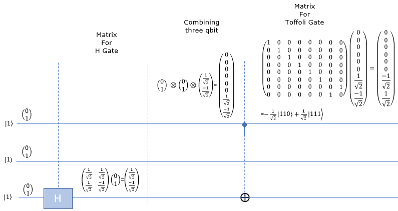
- __H-Toffoli-|111>
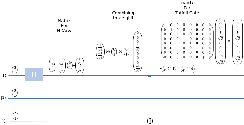
- H__-Toffoli-|111>
- HH_-Toffoli-|111>
- HHH-Toffoli-|111>
Summary of the basic circuits
Followings are short summary of basic circuit components which are most frequently used :
Pauli Gates (X, Y, Z) :- X Gate (Pauli-X, NOT gate): Flips the state of a qubit (|0> to |1> and vice versa). Used in many quantum algorithms for state inversion.
- Y Gate (Pauli-Y): A more complex rotation that affects both the real and imaginary components of a qubit's state.
- Z Gate (Pauli-Z, Phase-flip gate): Changes the phase of a qubit without changing its amplitude.
Hadamard Gate (H) :- Creates a superposition of |0> and |1> from a definite state. It's fundamental in algorithms like Grover's and in creating entangled states.
Phase Shift Gates (S, T) :- S Gate (πi/4 gate): Adds a phase of πi/2. Used for manipulating the phase of qubits.
- T Gate (πi/8 gate): Applies a πi/4 phase shift. It's important for more precise qubit phase manipulation.
Controlled Gates (CNOT, CZ, etc.): - CNOT Gate (Controlled-NOT): Entangles two qubits, flipping the second (target) qubit if the first (control) qubit is |1>. Essential for quantum teleportation and superdense coding.
- CZ Gate (Controlled-Z): Another form of controlled phase flip. Useful in creating various quantum states and in quantum error correction.
Swap Gate :- Swaps the states of two qubits. Useful in quantum algorithms where qubit position is relevant.
Toffoli Gate (CCNOT) :- A three-qubit gate that performs a NOT on the third qubit only when the first two qubits are in the |1⟩ state. Key in quantum error correction and reversible computing.
Fredkin Gate (Controlled-SWAP) :- A three-qubit gate that swaps the last two qubits if the first qubit is |1⟩. Used in quantum computing for operations that require conditional logic.
H-CNOT with |0> and |0>
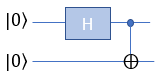
This example is for verification of following simple circuit : H(Hadamard) gate and CNOT gate connected in series as shown below. This circuit get two Qbits involved and I assume that the two bits getting into this circuit is |0> and |0>.
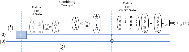
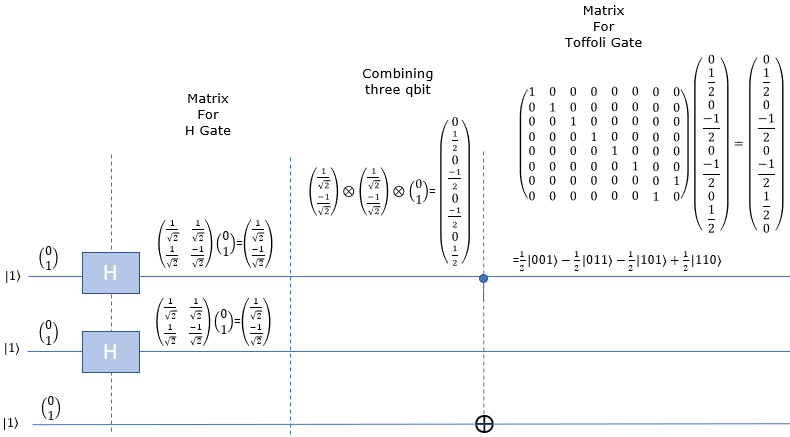
Now lets take a look at how these bits are mathematically transformed. At the beginning (leftmost), only the first Qbit |0> goes through Hadamard gate and transformed as in the second section. After the H gate, there is CNOT gate which take two Qbits as input. So we need to mathematically convert two separate Qbits into one two bit vector as shown in the third section. Then transform this two bit state vector with CNOT gate matrix as shown in the last section. The result tells that this circuit produce the superposition of |00> and |11> with 50 / 50 chances (probabilities).
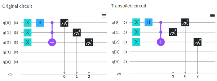
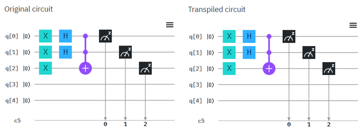
Now let's try with real Quantum Computer and see if the circuit works as explained in math shown above. Following is the circuit that I created. Left one is the original circuit that I created and the right one is what IBMQ software compiled. In this case there is no difference from the original one but sometimes you would see some different rearrangement of the component depending the structure of the circuit.

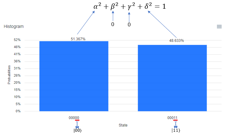
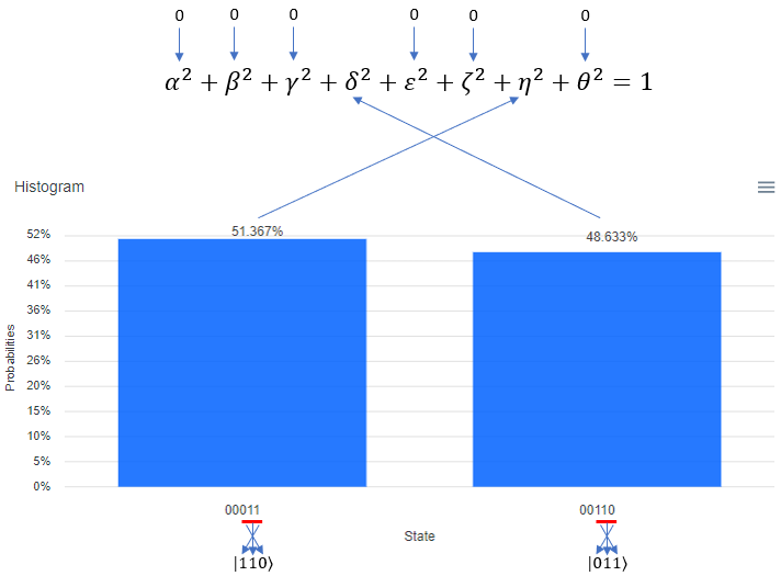
Following is the result of the execution. The percent value you see on top of each bar is the squred value of each coefficient in probability function. It means, 51.367 mean that "alpha squared" is 0.56367 and 48.633 mean that "delta squared" is 0.48633.
One very important thing to notice is that the Qbit state (the bit string) shown at the bottom of each plot. The LSB (the rightmost bit) indicate q[0] in the circuit and the MSB(the leftmost bit) indicate q[5] in the circuit. Keep this in mind when you translate this into the Qbit states in braket | > notation.
H-CNOT with |0> and |1>
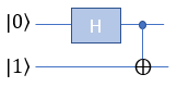
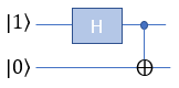
This example is for verification of following simple circuit : H(Hadamard) gate and CNOT gate connected in series as shown below. This circuit get two Qbits involved and I assume that the two bits getting into this circuit is |0> and |1>
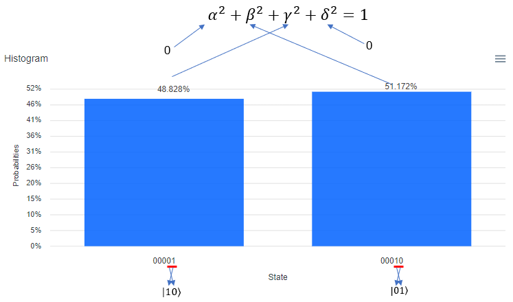
Now lets take a look at how these bits are mathematically transformed. At the beginning (leftmost), only the first Qbit |0> goes through Hadamard gate and transformed as in the second section. After the H gate, there is CNOT gate which take two Qbits as input. So we need to mathematically convert two separate Qbits into one two bit vector as shown in the third section. Then transform this two bit state vector with CNOT gate matrix as shown in the last section. The result tells that this circuit produce the superposition of |01> and |10> with 50 / 50 chances (probabilities).

Now let's try with real Quantum Computer and see if the circuit works as explained in math shown above. Following is the circuit that I created. Left one is the original circuit that I created and the right one is what IBMQ software compiled. In this case there is no difference from the original one but sometimes you would see some different rearrangement of the component depending the structure of the circuit.
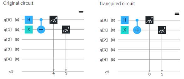
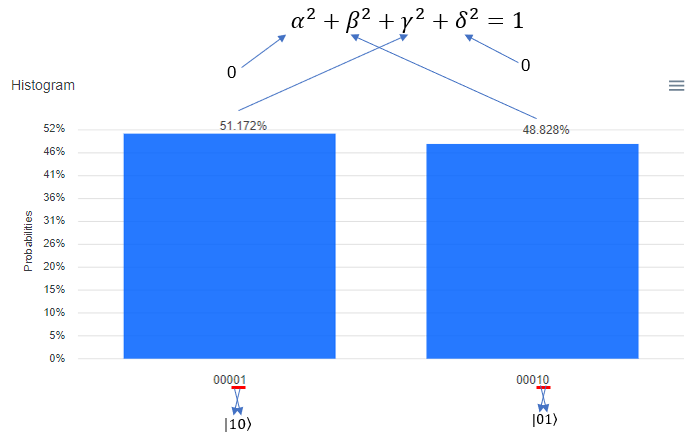
Following is the result of the execution. The percent value you see on top of each bar is the squred value of each coefficient in probability function. It means, 48.828 mean that "gamma squared" is 0.48828 and 51.172 mean that "beta squared" is 0.51172.
One very important thing to notice is that the Qbit state (the bit string) shown at the bottom of each plot. The LSB (the rightmost bit) indicate q[0] in the circuit and the MSB(the leftmost bit) indicate q[5] in the circuit. Keep this in mind when you translate this into the Qbit states in braket | > notation.
H-CNOT with |1> and |0>
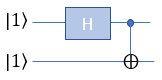
This example is for verification of following simple circuit : H(Hadamard) gate and CNOT gate connected in series as shown below. This circuit get two Qbits involved and I assume that the two bits getting into this circuit is |1> and |0>
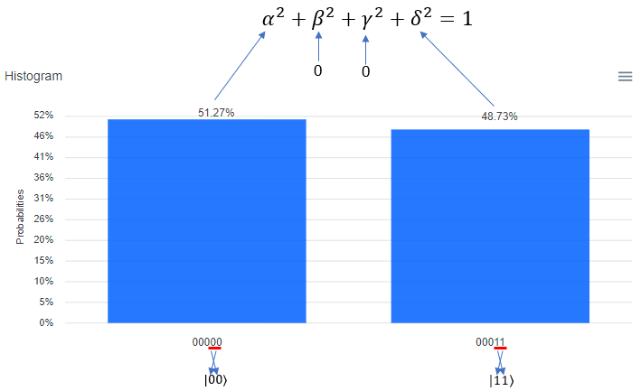
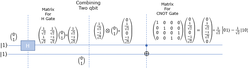
Now lets take a look at how these bits are mathematically transformed. At the beginning (leftmost), only the first Qbit |1> goes through Hadamard gate and transformed as in the second section. After the H gate, there is CNOT gate which take two Qbits as input. So we need to mathematically convert two separate Qbits into one two bit vector as shown in the third section. Then transform this two bit state vector with CNOT gate matrix as shown in the last section. The result tells that this circuit produce the superposition of |00> and |11> with 50 / 50 chances (probabilities).

Now let's try with real Quantum Computer and see if the circuit works as explained in math shown above. Following is the circuit that I created. Left one is the original circuit that I created and the right one is what IBMQ software compiled. In this case there is no difference from the original one but sometimes you would see some different rearrangement of the component depending the structure of the circuit.
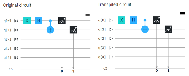
Following is the result of the execution. The percent value you see on top of each bar is the squred value of each coefficient in probability function. It means, 51.27 mean that "alpha squared" is 0.5127 and 48.73 mean that "delta squared" is 0.4873.
One very important thing to notice is that the Qbit state (the bit string) shown at the bottom of each plot. The LSB (the rightmost bit) indicate q[0] in the circuit and the MSB(the leftmost bit) indicate q[5] in the circuit. Keep this in mind when you translate this into the Qbit states in braket | > notation.
H-CNOT with |1> and |1>
This example is for verification of following simple circuit : H(Hadamard) gate and CNOT gate connected in series as shown below. This circuit get two Qbits involved and I assume that the two bits getting into this circuit is |1> and |1>
Now lets take a look at how these bits are mathematically transformed. At the beginning (leftmost), only the first Qbit |1> goes through Hadamard gate and transformed as in the second section. After the H gate, there is CNOT gate which take two Qbits as input. So we need to mathematically convert two separate Qbits into one two bit vector as shown in the third section. Then transform this two bit state vector with CNOT gate matrix as shown in the last section. The result tells that this circuit produce the superposition of |01> and |10> with 50 / 50 chances (probabilities).
Now let's try with real Quantum Computer and see if the circuit works as explained in math shown above. Following is the circuit that I created. Left one is the original circuit that I created and the right one is what IBMQ software compiled. In this case there is no difference from the original one but sometimes you would see some different rearrangement of the component depending the structure of the circuit.

Following is the result of the execution. The percent value you see on top of each bar is the squred value of each coefficient in probability function. It means, 51.172 mean that "beta squared" is 0.51172 and 48.828 mean that "gamma squared" is 0.48828.
One very important thing to notice is that the Qbit state (the bit string) shown at the bottom of each plot. The LSB (the rightmost bit) indicate q[0] in the circuit and the MSB(the leftmost bit) indicate q[5] in the circuit. Keep this in mind when you translate this into the Qbit states in braket | > notation.
HH-CNOT with |0> and |0>
This example is for verification of following simple circuit : H(Hadamard) gate and CNOT gate connected in series as shown below. This circuit get two Qbits involved and I assume that the two bits getting into this circuit is |0> and |0>
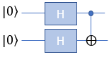
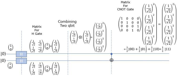
Now lets take a look at how these bits are mathematically transformed. At the beginning (leftmost), only the first Qbit |0> goes through Hadamard gate and transformed as in the second section. After the H gate, there is CNOT gate which take two Qbits as input. So we need to mathematically convert two separate Qbits into one two bit vector as shown in the third section. Then transform this two bit state vector with CNOT gate matrix as shown in the last section. The result tells that this circuit produce the superposition of |00> ,|01> ,|10> and |11> with sames chances (probabilities).
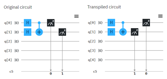
Now let's try with real Quantum Computer and see if the circuit works as explained in math shown above. Following is the circuit that I created. Left one is the original circuit that I created and the right one is what IBMQ software compiled. In this case there is no difference from the original one but sometimes you would see some different rearrangement of the component depending the structure of the circuit.
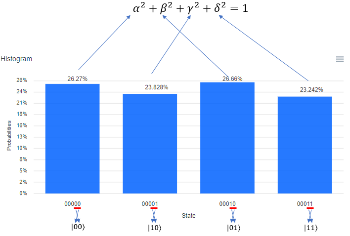
Following is the result of the execution. The percent value you see on top of each bar is the squred value of each coefficient in probability function. It means, 26.27 mean that "alpha squared" is 26.27, 23.66 indicating that beta squared is 23.66, 26.66 meaning gamma squared 23.828 and 23.242 mean that "delta squared" is 23.242.
One very important thing to notice is that the Qbit state (the bit string) shown at the bottom of each plot. The LSB (the rightmost bit) indicate q[0] in the circuit and the MSB(the leftmost bit) indicate q[5] in the circuit. Keep this in mind when you translate this into the Qbit states in braket | > notation.
HH-CNOT with |1> and |1>
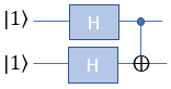
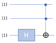
This example is for verification of following simple circuit : H(Hadamard) gate and CNOT gate connected in series as shown below. This circuit get two Qbits involved and I assume that the two bits getting into this circuit is |1> and |1>
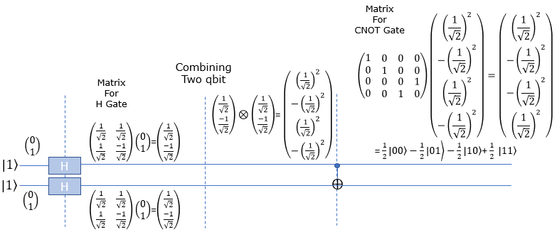
Now lets take a look at how these bits are mathematically transformed. At the beginning (leftmost), only the first Qbit |1> goes through Hadamard gate and transformed as in the second section. After the H gate, there is CNOT gate which take two Qbits as input. So we need to mathematically convert two separate Qbits into one two bit vector as shown in the third section. Then transform this two bit state vector with CNOT gate matrix as shown in the last section. The result tells that this circuit produce the superposition of |00> ,|01> ,|10> and |11> with sames chances (probabilities).
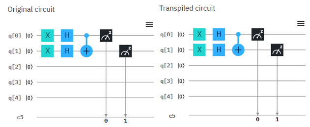
Now let's try with real Quantum Computer and see if the circuit works as explained in math shown above. Following is the circuit that I created. Left one is the original circuit that I created and the right one is what IBMQ software compiled. In this case there is no difference from the original one but sometimes you would see some different rearrangement of the component depending the structure of the circuit.
Following is the result of the execution. The percent value you see on top of each bar is the squred value of each coefficient in probability function. It means, 25.684 mean that "alpha squared" is 25.684, 24.023 indicating that beta squared is 24.023, 24.023 meaning gamma squared 24.023 and 25.488 mean that "delta squared" is 25.488.
One very important thing to notice is that the Qbit state (the bit string) shown at the bottom of each plot. The LSB (the rightmost bit) indicate q[0] in the circuit and the MSB(the leftmost bit) indicate q[5] in the circuit. Keep this in mind when you translate this into the Qbit states in braket | > notation.

nnH-Toffoli-|111>


Hnn-Toffoli-|111>
HHn-Toffoli-|111>


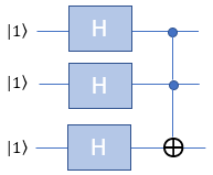
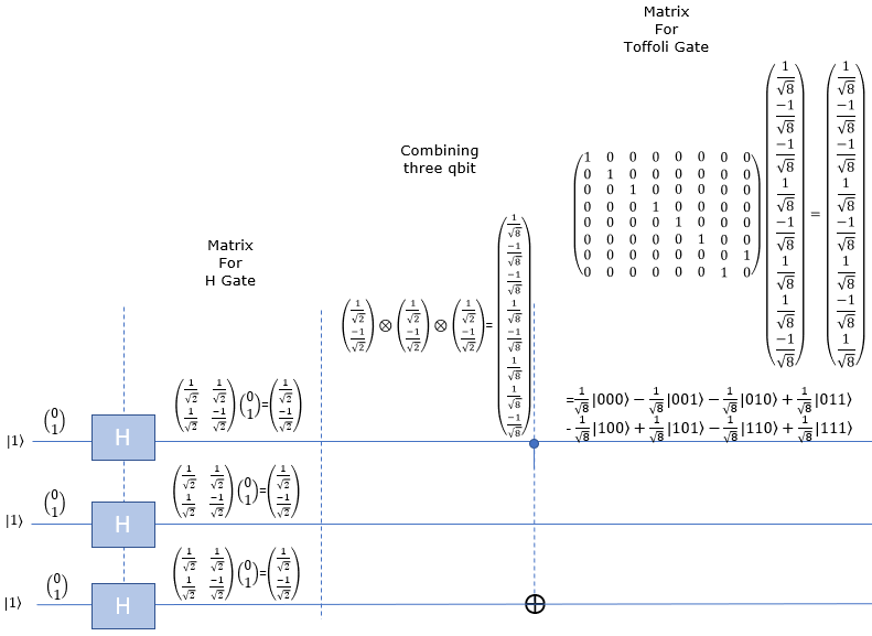
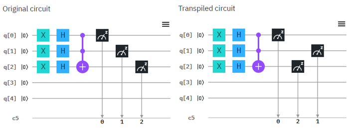
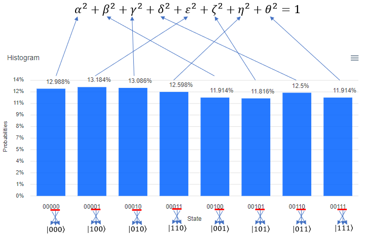
HHH-Toffoli-|111>