|
|
||||||||||||||||||||||||||||||||||||||||||||||||||||||||||||||||||||||||||||||||||||||||||||||||||||||||||||||||||||||||||||||||||||||||||||||||||||||||||||||||||||||||||||||||||||||||||||||||||||||||||||||||||||||||||||||||||||||||||||||||||||||||||||||||||||||||||||||||||||||||||||||||||||||||||||||||||||||||||||||||||||||||||||||||||||||||||||||||||||||
|
LTE RACH in DetailsRACH stands for Random Access Channel. This is the first message from UE to eNB when you power it on. Even though they use a little bit different name, in all cellular technology (CDMA, GSM, WCDMA, LTE) there is a specific signal that perform the same function. In CDMA, they call it 'Access Probe' as far as I know (but I don't have much knowledge on CDMA), in GSM they call it 'Channel Request', and in WCDMA / LTE they call it 'RACH'. In terms of eNB point of view, it would seem that it is getting this initial UE signal in almost random fashion (e.g, in Random timing , Random Frequency and in Random Identification) because it has no idea when a user turn on the UE (Actually it is not completely random, there are a certain range of agreement between UE and Network about the timing, frequency location and possible indentification, but in large scale it would look like working in random fashion). In terms of Radio Access Network implementation, handling RACH would be one of the most challenging job. Even in terms of protocol design, RACH design can be one of the most important / critical portions. If you have any experience of testing UE or UE modem chipset at the very early stage of the development, you would have noticed that RACH is the most challenging point in terms of troubleshooting. Why ? Before UE decided to send RACH signal (RACH preamble), there are many preconditions to be met as described in From Power-On to PRACH. If there are some problems in precondion stage, you have to completely rely on UE side log only, Network side log does not help anything. Even though you have access to the UE side log, depending on UE modem chipset.. some provides pretty detailed information but others does not provide much detailed information. Even if the UE log provides the detailed information, there are not many people who can properly interpret those information and find out the root cause of the problem. You would see a lot of issues and spend many many stressful days when you are testing the device at its early stage of the implementation, but once the device / modem is mature you would even forget about the fact that there is such a step called 'RACH' because this wouldn't cause any trouble.
Anyway... in short. RACH is one of the most important steps in LTE protocol (actually in any Cellular protocol) and there are a lot of details to be covered as below.
Why RACH ? (What is the functionality of RACH ?)The first question poping up in your mind when you first hear about the word RACH or RACH Process would be 'Why RACH ?', 'What is the functionality/purpose of RACH process ?', "Why we need this kind of complicated (looks over-complicated) ?'. For sure, it is not for confusing you :), RACH has very important functionality especially in LTE (and in WCDMA as well). The main purpose of RACH can be described as follows. i) Achieve UP link synchronization between UE and eNB ii) Obtain the resource for Message 3 (e.g, RRC Connection Request) In most of the communication (especially digital comunication regardless of whether it is wired or wireless), the most important precondition is to establish the timing synchronization between the reciever and transmitter. So whatever communication technology you would study, you would see some kind of synchronization mechanism that is specially designed for the specific communication.
In LTE (in WCDMA as well), the synchronization in downlink (Transmitter = eNB, Reciever = UE), this synchronization is achieved by the special synchronization channel (special physical signal pattern). Refer to Time Sync Process page for the details. This downlink sync signal gets broadcasted to everybody and it is get transmitted all the time with a certain interval. However in Uplink(Transmitter = UE, Reciever = eNB), it is not efficient (actually waste of energy and causing a lot of interference to other UEs) if UE is using this kind of broadcasting/always-on synchronization mechanism. You may easily understand this kind of problem. In case of uplink, this synchronization process should meet following criteria i) The synchronization process should happen only when there is immediate necessity ii) The synchronization should be dedicated to only a specific UE All the complicated/confusing stories in this page is mostly about the process specially designed mechanism to meet these criteria.
Another purpose of RACH process is to obtain the resource for Msg3 (Message 3). RRC Connection Request is one example of Msg3 and there are several different types of Msg3 depending on situation. You would figure out this part in reading through this page and this is not very complicated to understand. When RACH Process occurs ?It would be helpful to understand if you think about when 'RRC Connection' happens (or when PRACH process happens if you are interested in lower layer stuffs) in WCDMA. It would also be helpful if you think about when 'Channel Request' happens in GSM UE.
My impression of LTE RACH process is like the combination of PRACH process (WCDMA) and Channel Request (GSM). It may not be 100% correct analogy.. but anyway I got this kind of impression. In LTE, RACH process happens in following situation (3GPP specification, 10.1.5 Random Access Procedure of 36.300 ) i) Initial access from RRC_IDLE ii) RRC Connection Re-establishment procedure iii) Handover (Contention Based or Non Contetion Based) iv) DL data arrival during RRC_CONNECTED requiring random access procedure E.g. when UL synchronisation status is �non-synchronised� v) UL data arrival during RRC_CONNECTED requiring random access procedure E.g. when UL synchronisation status is "non-synchronised" or there are no PUCCH resources for SR available. vi) For positioning purpose during RRC_CONNECTED requiring random access procedure; E.g. when timing advance is needed for UE positioning Two types of RACH process : Contention-based and Contention-freeWhen a UE transmit a PRACH Preamble, it transmits with a specific pattern and this specific pattern is called a "Signature". In each LTE cell, total 64 preamble signatures are available and UE select randomly one of these signatures.
UE select "Randomly" one of these signatures ?
Does this mean that there is some possibility that multiple UEs send PRACH with identical signatures ?
Yes.
There is such a possibility. It means the same PRACH preamble from multipe UE reaches the NW at the same time.. this kind of PRACH collision is called "Contention" and the RACH process that allows this type of "Contention" is called "Contention based" RACH Process. In this kind of contention based RACH process, Network would go through additional process at later step to resolve these contention and this process is called "Contention Resolution" step.
But there is some cases that these kind of contention is not acceptable due to some reason (e.g, timing restriction) and these contention can be prevented. Usually in this case, the Network informs each of the UE of exactly when and which preamble signature it has to use. Of course, in this case Network will allocate these preamble signature so that it would not collide. This kind of RACH process is called "Contention Free" RACH procedure. To initiate the "Contention Free" RACH process, UE should be in Connected Mode before the RACH process as in Handover case.
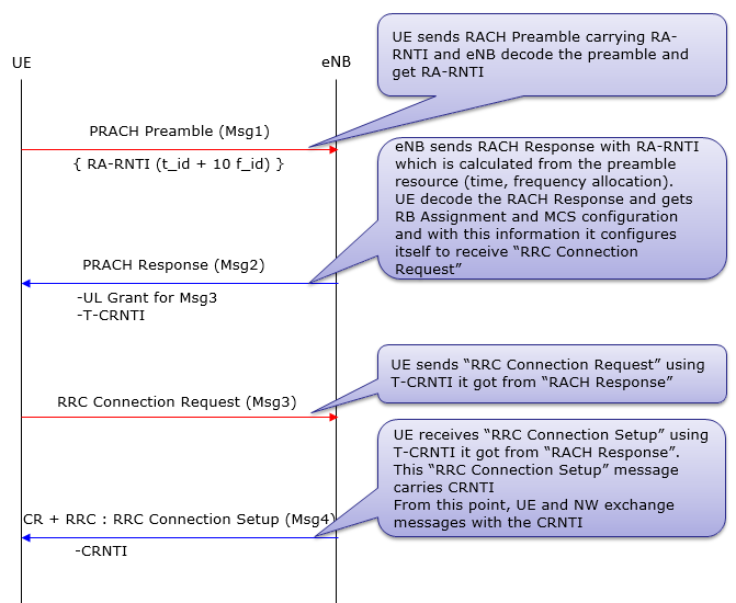
Typical 'Contention Based' RACH Procedure is as follows :
i) UE --> NW : RACH Preamble (RA-RNTI, indication for L2/L3 message size) ii) UE <-- NW : Random Access Response (Timing Advance, T_C-RNTI, UL grant for L2/L3 message) iii) UE --> NW : L2/L3 message iv) Message for early contention resolution
Now let's assume that a contention happened at step i). For example, two UEs sent PRACH. In this case, both of the UE will recieve the same T_C-RNTI and resource allocation at step ii). And as a result, both UE would send L2/L3 message through the same resource allocation(meaning with the same time/frequency location) to NW at step iii). What would happen when both UE transmit the exact same information on the exact same time/frequency location ? One possibility is that these two signal act as interference to each other and NW decode neither of them. In this case, none of the UE would have any response (HARQ ACK) from NW and they all think that RACH process has failed and go back to step i). The other possibility would be that NW could successfully decode the message from only one UE and failed to decode it from the other UE. In this case, the UE with the successful L2/L3 decoding on NW side will get the HARQ ACK from Network. This HARQ ACK process for step iii) message is called "contention resolution" process.
Typical 'Contention Free' RACH Procedure is as follows :
i) UE <--NW : RACH Preamble (PRACH) Assignment ii) UE --> NW : RACH Preamble (RA-RNTI, indication for L2/L3 message size) iii) UE <--NW : Random Access Response (Timing Advance, C-RNTI, UL grant for L2/L3 message) How the information is encoded into PRACH (RACH Preamble) ?In LTE, all the information (data) after PRACH Preamble has its own binary structure meaning that they are translated into a certain data structure. However, the information in PRACH Preamble is represented by purely physical properties. The physical properties that forms the information in PRACH are as follows. i) PRACH Preamble transmission Timing (t_id) ii) Location of PRACH transmission in frequency domain (f_id) iii) Sequence of the whole I/Q data of PRACH signal (one example shown below)
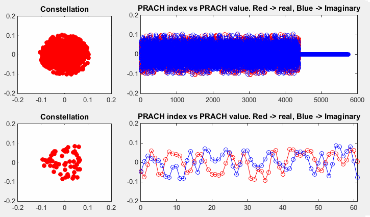
Following is the PRACH signal transmitted in Time Domain. (You may think this looks different from what you expected. You might have expect to see Zadoff-Chu sequence but this does not look like a Zadoff-Chu sequence. The Zadoff-Chu sequence for PRACH is in Frequency Domain, but this is the time domain sequence. The PRACH Zadoff-Chu is transformed to the time domain sequence as shown below via a transformation that is shown in How to Generate RACH signal section)
< PRACH Baseband Data Sequence >
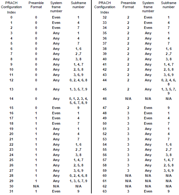
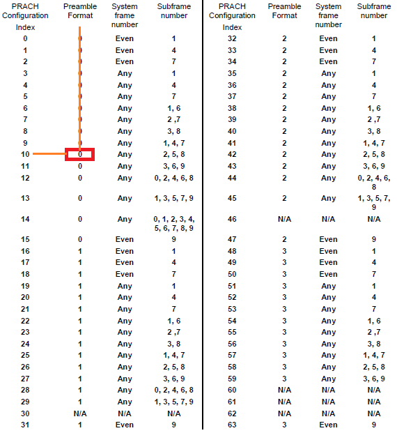
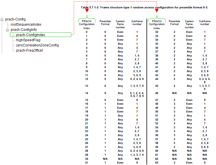
From item i) and ii), RA_RNTI is deribed as described in How can we get RA RNTI . From item iii), Preamble Index (RAPID) can be derived. You may not have much difficulties in understanding the derivation of RA_RNTI but it would not be that simple to understand the derivation of Preamble Index part. Most of the this page with a lot of equations and complex tables are related to this process, but I don't think I did a good job to simply/clearly describe this part. I will add another short sections in the future when I have everything cleared up in my brain. In the mean time, please refer to Matlab LTE Toolbox : PRACH page to get the intuitive (sorry it may not be that intuitive :) image in your brain and read the sections about PRACH Preamble signal generation part in this page. Of course, you would not get everything with single look. Nothing comes easy in engineering :) Exactly when and Where a UE transmit RACH ?To answer to this question, you need to refer to 3GPP specification TS36.211 - Table 5.7.1-2. This table would give you at which frame and subframe that UE is allowed to transmit a PRACH Preamble. As you see at this table, the prach preamble timing and prach preamble type is determined by PRACH Configuration Index. The, how PRACH Configuration Index is determined ? It is determined by SIB2 parameter prach-ConfigIndex.
< TS36.211 - Table 5.7.1-2 : PRACH Configuration Index>
Did you open the specification now ? It shows exactly when a UE is supposed to send RACH depending on a parameter called "PRACH Configuration Index".
For example, if the UE is using "PRACH Configuration Idex 0", it should transmit the RACH only in EVEN number SFN(System Frame Number). Is this good enough answer ? Does this mean that this UE can transmit the RACH in any time within the specified the SFN ? The answer to this question is in "Sub Frame Number" colulmn of the table. It says "1" for "PRACH Configuration Idex 0". It means the UE is allowed to transmit RACH only at sub frame number 1 of every even SFN.
Checking your understanding of the table, I will give you one question. With which "PRACH Configuration Idex", it would be the easiest for the Network to detect the RACH from UE ? and Why ?
The answer would be 14, because UE can send the RACH in any SFN and any slots within the frame.
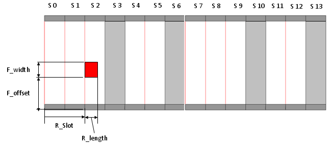
In a big picture, you should know all the dimmensions in the following diagram. (The Red rectangle is PRACH signal).
< PRACH Resource : Time domain and frequency domain >
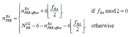
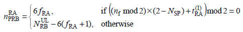
The R_Slot is determined by PRACH Configuration Index and R_length is determined by Premable format. F_offset is dermined by the following equation when the preamble format is 0~3. n_RA_PRBoffset in this equation is specified by prach-FreqOffset in SIB2. (Refer to 36.211 5.7 Physical random access channel for the details )
< FDD >
< TDD : Preamble format 0-3 >
< TDD : Preamble format 4 >
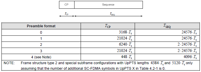
What is preamble format ?If you see the 36.211- table 5.7.1-1 show above, you see the column titled as "Preamble Format". What is the preamble format ? It is defined as following diagram.
You would see that the length of PRACH preamble varies depending on the preamble format. For example, the length of PRACH with preamble format 0 is (3186 + 24567) Samples. (As you know, one sample (Ts) is 1/30.72 (=0.03255) us. It is defined as 1/(15000 x 2048) seconds (=0.03255 us) in 36.211 4 Frame structure).
Why Multiple Preamble Format ?You may ask "Why we need this kind of multiple preamble format ?", especially "Why we need various PRACH format with different length in time ?".
First try to figure out what is the difference among preamble format based on the table above (Table 5.7.1-1) ? For simplicity, let's think of only format 0,1,2,3.
Let's look into T_SEQ (length of Sequence). You see format 0 and format 1 is made up of single copies of PRACH converted in time domain. Format 2 and 3 is made up of two copies of PRACH sequence concatenated. What would be the advantage that format 2,3 have over format 1,2. I think the longer T_SEQ would help decoding PRACH under noised condition because it provide longer correlation window to detect PRACH.
Now let's look at T_CP part. you would notice format 1 and 3 has much longer T_CP comparing to format 0 and 2. Longer CP would give you better tolerance in fading environment and reducing ISI even in highly fading environment.
Actually there is another important differences among each preamble format that is not explicitely shown in Table 5.7.1-1. It is guard time difference. How this guard time influence the cell size ? (Refer to the comments below or Cell Size Configuration in Random Access Procedure (I) - Preamble Format at LTE University)
I want to recommend a book titled "LTE : The UMTS From Theory to Practice" Section 19.4.2 The PRACH Structure. This is the material that describes the PRACH in the most detailed level I have ever read.
Just as a brief conclusion for cell size, we can rewrite the table as follows.
Note 1 : T_CP (in ms) = T_CP(in Ts) x 0.03255 x 1/1000, where 0.03225 is one Ts in us, 1/1000 is used to convert the unit from 'us' to 'ms' Note 2 : T_SEQ (in ms) = T_SEQ(in Ts) x 0.03255 x 1/1000, where 0.03225 is one Ts in us, 1/1000 is used to convert the unit from 'us' to 'ms' Note 3 : Guard Time (in ms) = Number of Subframe - Total Length Note 4 : Cell Radius is roughly the distance that the electromatic wave can travel during the guard time and devided by 2. In case of free space(in vacumm) it is roughly is 300 (km/ms) x Guard Time (ms) / 2. How to determined which Preamble format to use ?How UE know which Preamble format it has to use when it generate PRACH and trnasmit ? It is determined by following table. As you see, PRACH Configuration Index determines the Preamble Format to be used. For example, if PRACH Configuration Index is 10 as shown in the following example, the preamble format 0 is used. The you may ask 'Who determines PRACH Configuration index ?'. The answer is 'eNB determines it via prach-Configindex IE in SIB2'. Refer to prach-ConfigIndex section for the details.
< TS36.211 - Table 5.7.1-2 : Interpretation of PRACH Config >
How does Network knows exactly when UE will transmit the RACH ?It is simple. Network knows when UE will send the RACH even before UE sends it because Network tells UE when the UE is supposed to transmit the RACH. (If UE fails to decode properly the network information about the RACH, Network will fail to detect it even though UE sends RACH).
Following section will describe network informaton on RACH.
Which RRC Message contains RACH Configuration ?
It is in SIB2 and you can find the details in 3GPP 36.331.
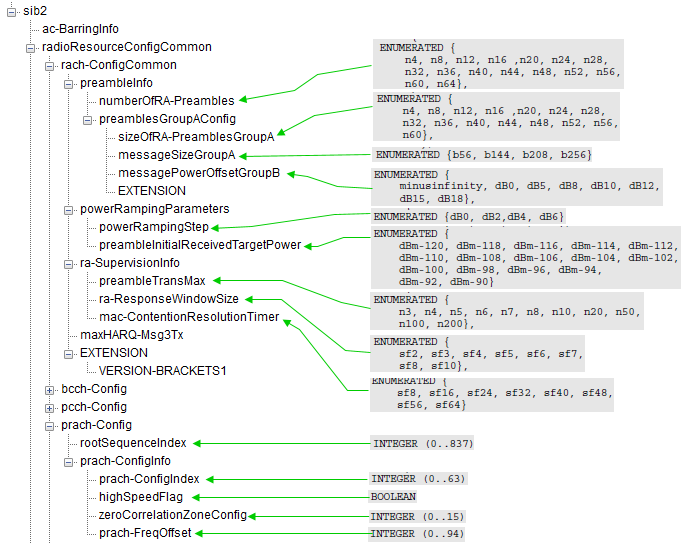
< RRC Parameters for RACH Operation >
How many RA-Preambles can be used ?Theoretically 64 PRACH preambles are available in total, but the number of the preambles available in a specific condition (e.g, in a certain cell, whether it is for attach or for handover etc) are determined by a couple of SIB2 parameters as shown below. sib2 radioResourceConfigCommon rach-ConfigCommon preambleInfo numberOfRA-Preambles: n52 (12) preamblesGroupAConfig sizeOfRA-PreamblesGroupA: n48 (11) messageSizeGroupA: b56 (0) messagePowerOffsetGroupB: dB5 (2) powerRampingParameters powerRampingStep: dB2 (1) preambleInitialReceivedTargetPower: dBm-104 (8) ra-SupervisionInfo preambleTransMax: n6 (3) ra-ResponseWindowSize: sf10 (7) mac-ContentionResolutionTimer: sf48 (5) maxHARQ-Msg3Tx: 4 ... prach-Config rootSequenceIndex: 22 prach-ConfigInfo prach-ConfigIndex: 3 ..0. .... highSpeedFlag: False zeroCorrelationZoneConfig: 5 prach-FreqOffset: 4 ...
additionalSpectrumEmission: 1 timeAlignmentTimerCommon: infinity (7)
There are two groups of RA-Preambles, Group A and Group B. Group A always exists and Group B exists only with the specific configuration in SIB 2 parameter. The determination of Group A and Group B is described in 36.321 5.1.1 Random Access Procedure initialization as follows.
If sizeOfRA-PreamblesGroupA is equal to numberOfRA-Preambles then there is no Random Access Preambles group B. The preambles in Random Access Preamble group A are the preambles (0 to sizeOfRAPreamblesGroupA � 1) and, if it exists, the preambles in Random Access Preamble group B are (the preambles sizeOfRA-PreamblesGroupA to numberOfRA-Preambles � 1) from the set of 64 preambles as defined in 36.211.
If Random Access Preambles group B exists, the thresholds, messagePowerOffsetGroupB and messageSizeGroupA, the configured UE transmitted power of the Serving Cell performing the Random Access Procedure, PCMAX, c [36.101], and the offset between the preamble and Msg3, deltaPreambleMsg3, that are required for selecting one of the two groups of Random Access Preambles (PCell only). // deltaPreambleMsg3 is power control related parameter (Refer to 36.331 and 36.213 5.1.1.1 UE behaviour for the details) How to Generate 64 PRACH Preamble Sequences ?As described above, the maximum number of PRACH Sequence a UE can use in a cell is 64. How these 64 different types of PRACH Sequence can be generated ? The procedure is as follows.
i) Generate a Zaddoff Chu sequence (849 samples) using rootSequenceIndex (let's call this sequence as 'base sequence') ii) Generate 64 different sequency by doing cyclic shift of the base sequence. The cyclic shift interval is determined by Ncs and the Ncs is determined by zeroCorrelationZoneConfig and Highspeedflag.
For example > Let's suppose SIB2 broadcast the parameters as follows. a) rootSequenceindex = 22 b) Highspeedflag = false c) zeroCorrelationZoneConfig = 5 From a), you will get the base Zaddoff-Chu sequence with u = 1 (Refer to rootSequenceIndex section if you want to know how this number is derived). From b) and c), you will get the Ncs (Cyclicshift interval) = 26 (Refer to zeroCorrelationZoneConfig and Highspeedflag. section if you want to know how this number is derived).
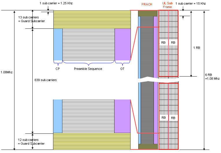
Now you can get the 64 different PRACH sequence as follows. PRACH Sequence[0] = base sequence PRACH Sequence[1] = do cyclic shift to base sequence by 1 * 26 samples PRACH Sequence[2] = do cyclic shift to base sequence by 2 * 26 samples .... PRACH Sequence[31] = do cyclic shift to base sequence by 31 * 26 samples PRACH Sequence[32] = do cyclic shift to base sequence +1 PRACH Sequence[33] = do cyclic shift to base sequence +1 by 1 * 26 samples PRACH Sequence[34] = do cyclic shift to base sequence +1 by 2 * 26 samples �� PRACH Sequence[63] = do cyclic shift to base sequence+1 by 31 * 26 samples PRACH Signal StructureFollowing figure shows the PRACH Premable signal structure in comparison with normal Uplink subframe. A couple of points to be specially mentioned are
How to generate RACH Signal ?You don't have to know the details of this procedure unless you are the DSP or FPGA engineer implementing LTE PHY.
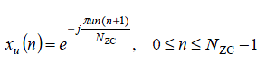
PRACH Signal in Frequency DomainFrequency Domain Sequence generation can be split into multiple steps as described below. The PRACH signal is derived from a Zadoff-Chu sequence, which has constant amplitude and zero autocorrelation properties. The ZC sequence is defined as: Just as a common sense about LTE, let's know that PRACH is a kind of ZaddOff Chu Sequence generated by the following equation. Be aware that this sequence is allocated along Frequency Domain.
Where: To allow multiple UEs to use the same root sequence, cyclic shifts (Cv) are applied. The cyclic shift value is determined by:
UE can select a logical root sequence based on RachRootSequenceIndex. Once UE pick a specific Logical Root Sequence Index value, it can figure out the physical root sequence index (u) based on Table 5.7.2-4.
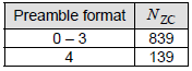
Nzc indicate 'number of data in the ZaddOff Chu Sequence'. This number is fixed to be 839 in preamble format 1,2,3 and 139 in preamble format 4.
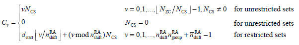
There are 64 preambles available for each cell and UE has to be able to generate the 64 preambles for the cell it want to camp on. You can easily generate 64 different preambles just by cyclically shifting an existing sequence, but there is a condition for this. All the preamle sequences should be othogonal to each other. Otherwise, various preambles from multiple UEs within the same cell can interfere each other. So we have to shift the generated sequence by a specifically designed value and this value is called Cv (Cyclic Shift Value) and it is defined as follows. (I think determining the Cv is one of the most complicated process in PRACH preamble generation because it gets involved with so many different parameters in cascading manner).
,Where NCS: Cyclic shift granularity.
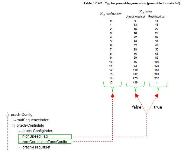
First, you would notice that we use different process to calculate Cv depending on whether we use 'unrestricted sets' or 'restricted sets'. This decision is made by 'Highspeedflag' information elements in SIB2. If Highspeedflag is set to be TRUE, we have to use 'restricted sets' and if Highspeedflag is false, we have to use 'unrestricted sets'.
N_cs is specified by zeroCorrelationZoneConfig information elements in SIB2. As you see in this mapping, N_cs values also gets different depending on whether we use 'restricted sets' or 'unrestricted sets'.
< Interpretation of highSpeedFlag / zeroCorrelationZoneConfig >
Now let's look at how we get Nzc. This is pretty straightforward. Nzc is determined by the following table. (Preamble format 4 is used only in TDD LTE. So in case of FDD, you can say Nzc is fixed to be 839)
< 36.211-Table 5.7.2-1: Random access preamble sequence length >
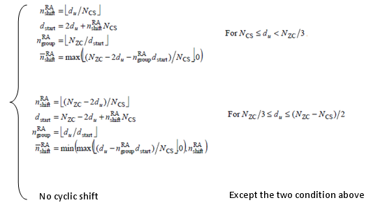
If the Preamble is using the unrestricted sets, it is pretty simple. You only have to know Nzc, Ncs to figure out Cv. The problem is when the Preamble is using the 'restricted sets'. As you see the equation above, you need to know the following 4 values to figure out Cv in 'restricted sets'.
where
The problem is that the calculation of these four variable is very complicated as shown below.
Following is high level description of each of the cases
Case 1: NCS ≤ du < NZC/3
Case 2: NZC/3 ≤ du ≤ (NZC - NCS)/2
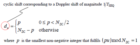
Default Case: No Cyclic Shift You would noticed that you need another value to calculate to determine which of the three case we have to use. It is du. So we need another process to determine du.
Finding p:
Purpose of du:
Significance in the Context of PRACH:
We went through a complicated procedure just to determin one number (Cv). Once we get Cv, we can generate multiple preambles using the following function. This represents the generation of cyclically shifted preambles from a base Zadoff-Chu (ZC) sequence.
What does this mean ?
Purpose of the Formula
Application in PRACH
PRACH Signal in Time DomainAnyway, now we got a PRACH Preamble sequence in hand, but this is not all. In order to transmit this data. We have to convert this data into a time domain sequence and this conversion is done by the following process.
Once the frequency domain Zaddoff Chu sequence is obtained as described above(i.e, frequency domain Zadoff-Chu sequence), you can plug it into the following equation and with some additional parameters you can generate the time domain PRACH sequence. The process involves converting the sequence and incorporating additional parameters to make the signal ready for transmission.
< PRACH Signal Generation in Time Domain >
Below is an explanation of the key components and steps:
Why separate algorithm for Frequency Domain and Time Domain Sequence Generation ?In rach signal generation, why we need separate signal generation algorithm for time domain instead of just doing FFT of frequency domain sequence ? The need for a separate signal generation algorithm in the time domain for PRACH signals, instead of directly applying an Inverse FFT (IFFT) to the frequency domain Zadoff-Chu sequence, arises due to the following reasons:
Exactly when and where Network transmit RACH ResponseWe all knows that Network should transmit RACH Response after it recieved RACH Preamble from UE, but do we know exactly when, in exactly which subframe, the network should transmit the RACH Response ? The following is what 3GPP 36.321 (section 5.1.4) describes.
Once the Random Access Preamble is transmitted and regardless of the possible occurrence of a measurement gap, the UE shall monitor the PDCCH for Random Access Response(s) identified by the RA-RNTI defined below, in the RA Response window which starts at the subframe that contains the end of the preamble transmission [7] plus three subframes and has length ra-ResponseWindowSize subframes.
It means the earliest time when the network can transmit the RACH response is 3 subframe later from the end of RACH Preamble. Then what is the latest time when the network can transmit it ? It is determined by ra-ResponseWindowSize. This window size can be the number between 0 and 10 in the unit of subframes. This means that the maximum time difference between the end of RACH preamble and RACH Response is only 12 subframes (12 ms) which is pretty tight timing requirement. How is the RACH Preamble Power determined ?The RACH Preamble (PRACH) power varies depending on cases as described below (Based on 36.321 - 5.1.3) : NOTE : In this section, I will describe on PRACH power only for Legacy LTE. The power varies a little for LTE BL/CE (LTE Cat M1) and LTE NB(Cat M2) which will be explained in separate page. Basically PRACH power is determined by OpenLoopPower control algorithm. It would be good idea to read Open Loop and Closed Loop Power Control Page if you are not familiar with the concept.
Regardless of the cases, the PRACH Power (P_PRACH) is determined by the following equation.
P_PRACH = min{P_CMAX, PREAMBLE_RECEIVED_TARGET_POWER + PL}
PL stands for Path Loss between eNB Tx antenna and UE Rx Antenna. PREAMBLE_RECEIVED_TARGET_POWER is the PRACH power that eNB expect to recieve.
The meaning of this equation is as follows : i) Calculate PREAMBLE_RECEIVED_TARGET_POWER + PL ii) if the calculated value is less than P_CMAX(23 dBm), transmit the PRACH at the calculated value. if the calculated value is greater than P_CMAX(23 dBm), transmit the PRACH at P_CMAX
Now let's think of how "PREAMBLE_RECEIVED_TARGET_POWER + PL" is calculated. This calculation varies depending on cases asdescribed below.
First let's see how PREAMBLE_RECEIVED_TARGET_POWER. This is calculated as follows.
PREAMBLE_RECEIVED_TARGET_POWER = preambleInitialReceivedTargetPower(in SIB2) + DELTA_PREAMBLE
PREAMBLE_RECEIVED_TARGET_POWER = preambleInitialReceivedTargetPower(in SIB2) + DELTA_PREAMBLE + (PREAMBLE_TRANSMISSION_COUNTER � 1) * powerRampingStep NOTE : As you see here, PREAMBLE_RECEIVED_TARGET_POWER will increase everytime it gets retransmitted NOTE : PREAMBLE_TRANSMISSION_COUNTER starts from 1 at the first PRACH and get increased by 1 everytime PRACH get retransmitted.
Now you would ask on how to figure out preambleInitialReceivedTargetPower and powerRampingStep. These are infromed to UE in SIB2 as shown below.
+-sib2 ::= SEQUENCE [00] +-ac-BarringInfo ::= SEQUENCE OPTIONAL:Omit +-radioResourceConfigCommon ::= SEQUENCE | +-rach-Config ::= SEQUENCE | | +-preambleInfo ::= SEQUENCE [0] | | | +-numberOfRA-Preambles ::= ENUMERATED [n52] | | | +-preamblesGroupAConfig ::= SEQUENCE OPTIONAL:Omit | | +-powerRampingParameters ::= SEQUENCE | | | +-powerRampingStep ::= ENUMERATED [dB2] | | | +-preambleInitialReceivedTargetPower ::= ENUMERATED [dBm-104] | | +-ra-SupervisionInfo ::= SEQUENCE | | | +-preambleTransMax ::= ENUMERATED [n6] | | | +-ra-ResponseWindowSize ::= ENUMERATED [sf10] | | | +-mac-ContentionResolutionTimer ::= ENUMERATED [sf48]
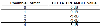
You would still find one unknown parameter called DELTA_PREAMBLE. It is determined by which Preamble Format is used as shown below. Now you may ask how Preamble Format is determined. It is determined by prach-Configindex in SIB2.
< 36.321 - Table 7.6-1: DELTA_PREAMBLE values. >
Now let's think of how UE can estimate the path loss between eNB Tx antenna and UE Rx antenna. Technically it is simple. It can be calculated as follows. PL = eNB Transmitter Power - UE Reciever Power UE has 'UE Reciever Power' by direct measurement. The problem is how UE can figure out eNB transmitter Power. It is not possible for UE to figure this out direct measurement. eNB should tell UE of its transmitted power. This eNB Tx power is notifed by a SIB2 parameter referenceSignalPower as shown below.
+-sib2 ::= SEQUENCE [00] +-ac-BarringInfo ::= SEQUENCE OPTIONAL:Omit +-radioResourceConfigCommon ::= SEQUENCE | +-rach-Config ::= SEQUENCE | | +-preambleInfo ::= SEQUENCE [0] | | | +-numberOfRA-Preambles ::= ENUMERATED [n52] | | | +-preamblesGroupAConfig ::= SEQUENCE OPTIONAL:Omit | | +-powerRampingParameters ::= SEQUENCE | | | +-powerRampingStep ::= ENUMERATED [dB2] | | | +-preambleInitialReceivedTargetPower ::= ENUMERATED [dBm-104] | | +-ra-SupervisionInfo ::= SEQUENCE | | | +-preambleTransMax ::= ENUMERATED [n6] | | | +-ra-ResponseWindowSize ::= ENUMERATED [sf10] | | | +-mac-ContentionResolutionTimer ::= ENUMERATED [sf48] | | +-maxHARQ-Msg3Tx ::= INTEGER (1..8) [4] | +-bcch-Config ::= SEQUENCE | +-pcch-Config ::= SEQUENCE | +-prach-Config ::= SEQUENCE | +-pdsch-Config ::= SEQUENCE | | +-referenceSignalPower ::= INTEGER (-60..50) [18] | | +-p-b ::= INTEGER (0..3) [0]
Let's take an example case and apply all the stuffs described above. Let's assume that UE decoded following SIB parameters.
Now assume that UE measures RSRP at its reciever antenna as follows.
From these information, you can calculate the following value
PREAMBLE_RECEIVED_TARGET_POWER = preambleInitialReceivedTargetPower(in SIB2) + DELTA_PREAMBLE = -104 + 0 = -104
Now you can calculate the PathLoss as below.
PL = (referenceSignalPowerin SIB2) - (RSRP measuredt at UE) = 18 - (-80) = 98
Then just plug these into PRACH power equation and you get the result as follows.
P_PRACH = min{23, -104+98 } = min(23, -6) = 6 dBm PRACH Parameters and Physical MeaningPRACH employs specific configurations to define how and where the random access preamble is transmitted. These parameters collectively define PRACH transmission behavior, optimize performance under varying network conditions, and ensure reliable UE access.
prach-ConfigIndexThis parameter determines what type of preamble format should be used and at which system frame and subframe UE can transmit PRACH Preamble. It determines the PRACH configuration, including time-domain opportunities (subframe allocation) and frequency domain resources for random access.
This parameter is configured in sib2 as follows. sib2 radioResourceConfigCommon rach-ConfigCommon preambleInfo numberOfRA-Preambles: n52 (12) powerRampingParameters powerRampingStep: dB2 (1) preambleInitialReceivedTargetPower: dBm-104 (8) ra-SupervisionInfo preambleTransMax: n6 (3) ra-ResponseWindowSize: sf10 (7) mac-ContentionResolutionTimer: sf48 (5) maxHARQ-Msg3Tx: 4 ... prach-Config rootSequenceIndex: 22 prach-ConfigInfo prach-ConfigIndex: 3 ..0. .... highSpeedFlag: False zeroCorrelationZoneConfig: 5 prach-FreqOffset: 4 ...
additionalSpectrumEmission: 1 timeAlignmentTimerCommon: infinity (7)
The meaning of prach-ConfigIndex is defined by the following table. If you are not familiar with how to interpret this table. Refer to the section Exactly when and Where a UE transmit RACH ?
zeroCorrelationZoneConfig and HighspeedflagzeroCorrelationZoneConfig and Highspeedflg Ie is to specify the cyclic shift intervals to generate 64 PRACH Sequence from a single base sequence. These IE(information elements) are specified in SIB2 as in the example below. sib2 radioResourceConfigCommon rach-ConfigCommon preambleInfo numberOfRA-Preambles: n52 (12) powerRampingParameters powerRampingStep: dB2 (1) preambleInitialReceivedTargetPower: dBm-104 (8) ra-SupervisionInfo preambleTransMax: n6 (3) ra-ResponseWindowSize: sf10 (7) mac-ContentionResolutionTimer: sf48 (5) maxHARQ-Msg3Tx: 4 ... prach-Config rootSequenceIndex: 22 prach-ConfigInfo prach-ConfigIndex: 3 ..0. .... highSpeedFlag: False zeroCorrelationZoneConfig: 5 prach-FreqOffset: 4 ...
additionalSpectrumEmission: 1 timeAlignmentTimerCommon: infinity (7)
This configures the cyclic shift applied to the PRACH sequence to create multiple orthogonal preambles.
A boolean flag indicating whether the PRACH configuration is optimized for high-speed UEs.
If you apply the values in the example above, you would get the Ncs value of 26. (Pick the number at the cross of column 'Unrestricted Set (HighSpeedFlack = False) and the row of Ncs 5)
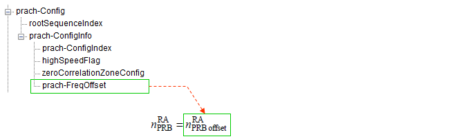
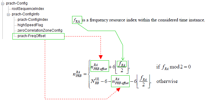
highSpeedFlag : TRUE corresponds to Restricted set and FALSE to Unrestricted set prach-FreqOffsetprach-FreqOffset is the parameter that determines the location of PRACH preamble in frequency domain. This location in frequency domain is calculated in the unit of PRM index and calulcated by following equation. This Specifies the frequency offset for PRACH transmission within the uplink carrier.
As you see, the equation gets different depending on Preamble Format.
< FDD : PRACH Preamble Location for Preamble Format 0-4>
< TDD : PRACH Preamble Location for Preamble Format 0-3 >
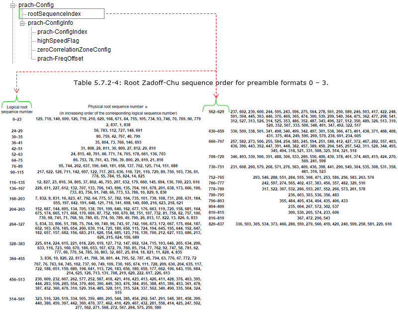
rootSequenceIndexThis specifies the root Zadoff-Chu sequence index used to generate the PRACH preamble sequences. There are 838 root Zadoff-Chu sequences available for preambles. The length of each root sequence is 839. RootConfigurationIndex informs the UE on which sequence to use via SIB2 as shown below.
This parameter is configured in SIB2 as follows sib2 radioResourceConfigCommon rach-ConfigCommon preambleInfo numberOfRA-Preambles: n52 (12) powerRampingParameters powerRampingStep: dB2 (1) preambleInitialReceivedTargetPower: dBm-104 (8) ra-SupervisionInfo preambleTransMax: n6 (3) ra-ResponseWindowSize: sf10 (7) mac-ContentionResolutionTimer: sf48 (5) maxHARQ-Msg3Tx: 4 ... prach-Config rootSequenceIndex: 22 prach-ConfigInfo prach-ConfigIndex: 3 ..0. .... highSpeedFlag: False zeroCorrelationZoneConfig: 5 prach-FreqOffset: 4 ...
additionalSpectrumEmission: 1 timeAlignmentTimerCommon: infinity (7)
This rootSequenceIndex is a logical value. The real number (physical number) is called 'u' which is a variable used to generate PRACH ZaddOff-Chu Sequence. The mapping between the rootsequenceIndex and 'u' is determined by the following table. For example, if the rootsequenceIndex is 22 as in the example shown above, the 'u' become '1' according to this table.
You may wonder how the 'rootsequenceIndex = 22' is translated to 'u = 1'. It is simple. From the Table 5.7.2-4, you can pick the Logical root sequence number range that the rootsequenceIndex belong to. For example, the range that 22 belong to is as follows.
Then you can convert the above row into a table as shown below and you can easily figure out the 'roolSequenceIndex=22' is mapped to 'u=1'.
Just for another practice, let me give you another example. What would be the 'u' for the rootSequenceIndex=696 ? The answer is as follows :
Then you can convert the above row into a table as shown below and you can easily figure out the 'rootSequenceIndex=606' is mapped to 'u=344'.
< 36.211 Table 5.7.2-4: Root Zadoff-Chu sequence order for preamble formats 0 � 3 >
RACH Procedure during Initial Registration - RACH Procedure SummaryFollwing is an example of RACH procedure which happens during the initiail registration. If you will be an engineer who is working on protocol stack development or test case development, you should be very familiar with all the details of this process.
< RACH Procedure during Initial Registration >
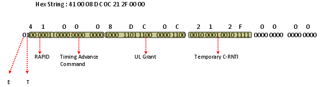
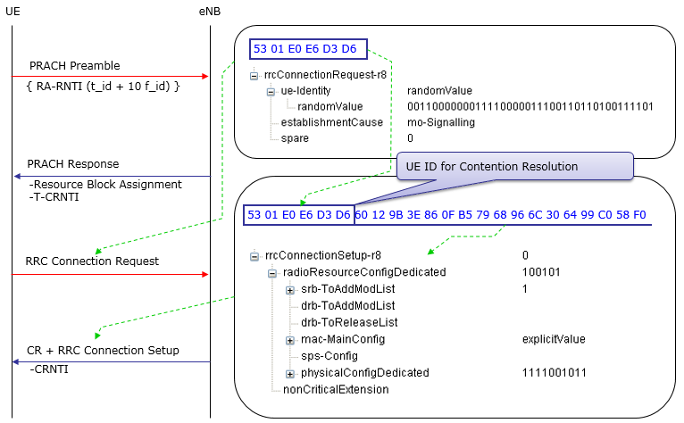
Again, we have to know every details of every step without missing anything to be a developer, but of course it is not easy to understand everything at a single shot. So, let's start with something the most important part, which I think is the details of RACH response. Following diagram shows one example of RACH Response with 5 Mhz bandwidth. We don't have to memorize the detailed value itself but should be familiar with the data format and understand which part of this bit string means what.
< An Example of RAR (RACH Response) >
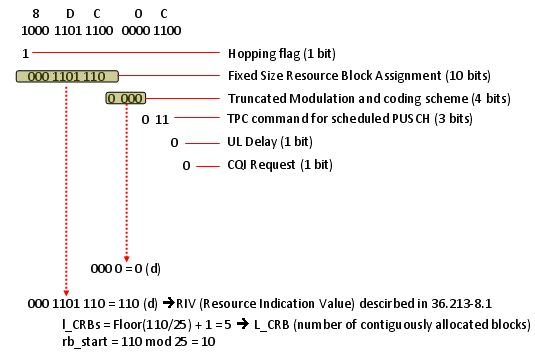
If you decode UL Grant part, you will get the following result. You will notice that the information it carries would be very similar to DCI format 0 which carries Resource Allocation for uplink data. This information in UL Grant in RACH Response message is the resource allocation for msg3 (e.g, RRC Connection Request). Note : This is example of RAR for System BW 5 Mhz. If the sytem BW gets different, you should have different RIV values (if you want to have the same Start_RB, N_RB as in this example) or you will have different Start_RB, N_RB (if you keep RIV as below and just change the system BW)
< Example of UL Grant in RAR >
Let me describe this procedure in verbal form again.
i) UE initiate a Random Access Procedure on the (uplink) Random Access Channel (RACH).(The location of RACH in the frequency/time resource grid the RACH is known to the mobile via the (downlink) Broadcast Channel (BCH))
ii) Network sends a Random Access Response Message(RARM) at a time and location on the Physical Downlink Shared Channel (PDSCH) (The time and location of RARM on PDSCH can be calculated from the time and location the random access message was sent. This message contains the random identity sent by the device, a Cell Radio Network Temporary ID (T_C-RNTI) which will be used for all further bandwidth assignments, and an initial uplink bandwidth assignment)
iii) The mobile device then uses the bandwidth assignment to send a short (around 80 bits) RRC Connection Request message which includes it's identity which has previously been assigned to it by the core network
Only the step i) uses physical-layer processing specifically designed for random access. The remaining steps utilizes the same physical layer processing as used for normal uplink and downlink data transmission How can we get RA RNTI ?�5.1.4 Random Access Response reception" in "TS36.321� says how to calculate RA_RNTI as follows.
The RA-RNTI associated with the PRACH in which the Random Access Preamble is transmitted, is computed as: RA-RNTI = 1 + t_id + 10 * f_id Where t_id is the index of the first subframe of the specified PRACH (0 <≤ t_id <10), and f_id is the index of the specified PRACH within that subframe, in ascending order of frequency domain (0≤ f_id< 6).
For FDD, f_id is fixed as 0.
Therefore, RA_RNTI is decided by the sending timing (SubFrame) of PRACH Preamble by UE. It means that (the subframe number (number between 0000~0009) of PRACH transmission + 1) is RA-RNTI. It means that UE specifies RA_RNTI by the sending timing (SubFrame) of PRACH Preamble. An Example of Full RACH ProcessFollowing is an example of Full RACH process with a commercialized LTE device and LTE Network Emulator. I would not explain anything in detail. Just check if the following diagram make any sense to you. If it does, I would say you understand all the details that I explained above.
< RACH Sequence during Initial Attach >
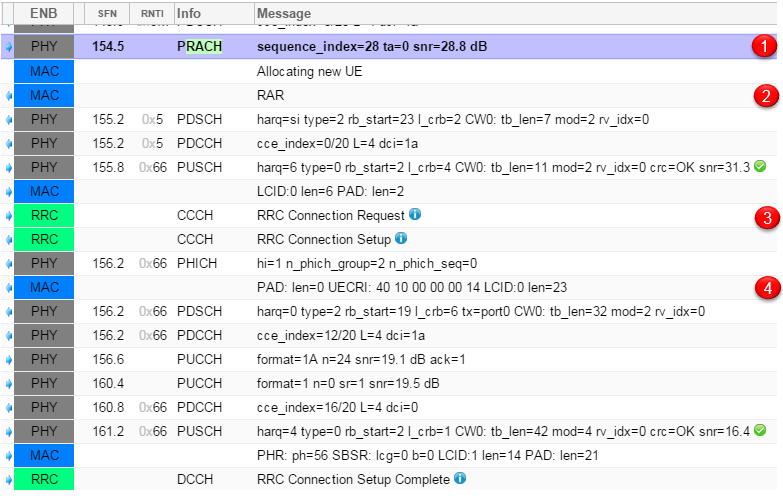
Following is an example of real RACH procedure happening between a UE and Amarisoft OTS. Log shown here is a screencapture of Amarisoft Web Logging tool.
< Example of RACH Process during Initial Attach >
PRACH RetransmissionMost part of previous section was about the ideal RACH process, which means that UE send PRACH and Network send RACH Response at the first trial and went through all the way to the end of process at the first trial.
What if UE does not receive RACH Response at the first trial ? What is UE supposed to do in this case ? The answer is simple. Just retry (resend) PRACH. (In this case, UE might not have any Backoff Indicator value which normally transmitted in MAC CE being sent with RAR).
There is another case where UE needs to retry PRACH. It is the case where UE received RAR from the network, but the RAPID is not for it (It means that RAR is not for some other UE). In this case, it is highly probable that a Backoff Indicator value is transmitted with RAR to control the PRACH retransmission timing.
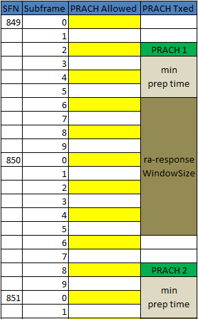
Then you would have more question. ("I" in the following description is "UE") i) When do I have to retry ? (What should be the time delay between the previous transmission and the next transmission ?) ii) Do I have to retransmit the PRACH with the same power as previous one ? Or try with a little bit higher power ? If I have to try with a little bit higher power, how much power do I have to increase ? iii) If I keep failing to receive RACH response, how many time I have to retry ? Do I have to retry until the battery runs out ? or retry only several times and give up ? If I have to give up after a certain amount of retry, exactly how many times do I have to retry ? The answers to all of these questions are provided by the network. The answer (instruction) to question i) is provided by Network via a special RAR MAC PDU called "Backoff Indicator". The answer to question ii) and iii) are provided by Network via SIB2 as follows. powerRampingStep is the answer to question ii) and preambleTransMax is the answer to question iii). In the following example, powerRampingStep = dB2. It means UE has to increase PRACH power by 2 dB everytime it retries. preambleTransMax = n6. It means UE retries PRACH retransmit only 6 times and then give up. (This is my understanding at least as of now. But trying with real device, I see many cases UE does not give up even after it reaches preambleTransMax. I will get this updated as I find more)
| +-radioResourceConfigCommon ::= SEQUENCE | | +-rach-Config ::= SEQUENCE | | | +-preambleInfo ::= SEQUENCE [0] | | | | +-numberOfRA-Preambles ::= ENUMERATED [n52] | | | | +-preamblesGroupAConfig ::= SEQUENCE OPTIONAL:Omit | | | +-powerRampingParameters ::= SEQUENCE | | | | +-powerRampingStep ::= ENUMERATED [dB2] | | | | +-preambleInitialReceivedTargetPower ::= ENUMERATED [dBm-104] | | | +-ra-SupervisionInfo ::= SEQUENCE | | | | +-preambleTransMax ::= ENUMERATED [n6] | | | | +-ra-ResponseWindowSize ::= ENUMERATED [sf10] | | | | +-mac-ContentionResolutionTimer ::= ENUMERATED [sf48] | | | +-maxHARQ-Msg3Tx ::= INTEGER (1..8) [4] Additional Factors : PRACH Config Index (in SIB2) Backoff Indicator (in MAC CE) T-300 (in SIB2) Following is an example of PRACH Retry being observed in a real device. This is the case where UE send PRACH and NW does not send RAR (Yellow cell indicates the timing determined by PRACH Config Index when UE is allowed to send PRACH. See Exactly when and where Network transmit RACH Response . Green cell indicates the timing when UE send PRACH in this specific example)
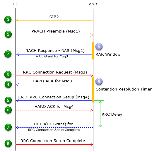
RACH Process Overview In DiagramsI have explained long about the RACH process. Now you may ask "What is the trigger that let UE initiate the RACH process ?". You will see various triggers in 3GTS 36.300 (10.1.5) : Overall description of RACH Process. "Turning on UE" is one of the trigger for sure. And following is another trigger for this process. RACH Procedure on Initial RegistrationThis is basically the same sequence that I explained in previous sections, but I simplified the diagram in previous sections to let reader focused more on messaging part of RACH procedure. In this diagram, you see some additional steps like HARQ ACK, DCI 0 (UL Grant). This flow is more similar to real live network procedure.
< RACH Procedure during Initial Registration >
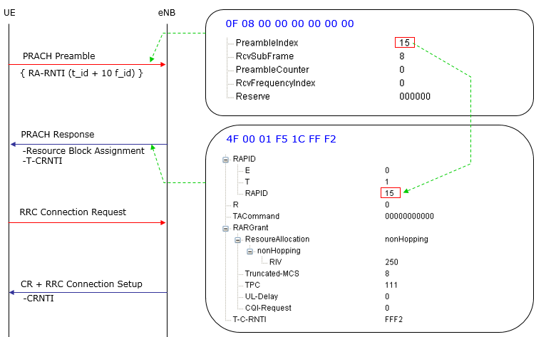
Following is one example for this sequence that I got from live network and summarized with important parameters. I hope this can be a good practice for you. (Note : This is with FDD)
< Live network Example of RACH process for Initial Attach >
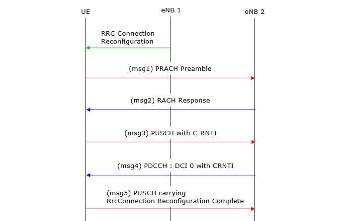
RACH Procedure on Handover - Contention BasedThis case illustrates the Contention-Based Random Access (CBRA) procedure during a handover in LTE, which involves transitioning a UE (User Equipment) from one eNB (source eNodeB) to another (target eNodeB)
Followings are brief descriptions on each of the steps
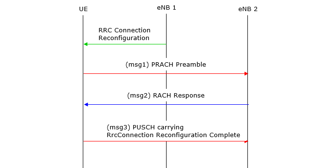
RACH Procedure on Handover - Contention FreeThis diagram explains the Contention-Free Random Access (CFRA) procedure during a handover in LTE. Unlike contention-based RACH, CFRA is used when the target eNB (eNB 2) assigns a dedicated preamble to the UE to avoid contention.
For the complete handover procedure with this type of RACH proceder, refer to this note. In most handover, this kind of contention free RACH procedure is used since UE and eNB is already in sync with C-RNTI.
Here's a breakdown of the steps:
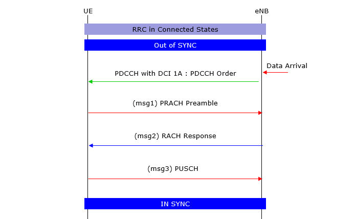
RACH Procedure on DL Data Arrival when Out-of-Sync - Contention FreeThis scenario depicts the Contention-Free RACH Procedure for Downlink (DL) Data Arrival When Out-of-Sync. It explains how the eNB triggers synchronization recovery using a PDCCH Order in a connected state when the UE is out of sync.
PDCCH order is a mechanism for eNB to trigger RACH procedure in connected mode in order to recover the sync. Refer to PDCCH Order page for the details of RACH Triggered by PDCCH Order. I wrote a separate page because there are pretty much details on PDCCH Order itself.
Here's a step-by-step explanation:
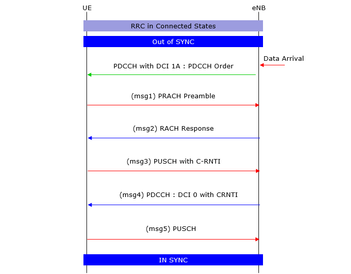
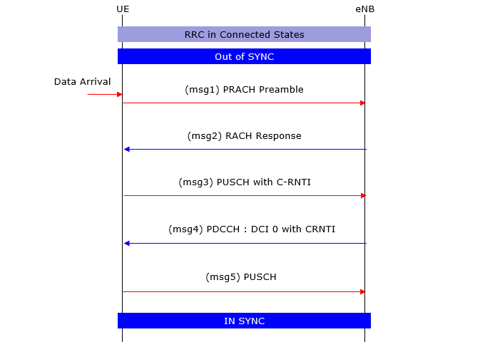
RACH Procedure on DL Data Arrival when Out-of-Sync - Contention BasedThis scenario explains the Contention-Based RACH Procedure for Downlink (DL) Data Arrival When Out-of-Sync in LTE. In this procedure, the UE is out of uplink synchronization and relies on a contention-based random access mechanism to restore sync.
Here�s a detailed step-by-step explanation:
RACH Procedure on UL Data Arrival when Out-of-SyncThis scenario explains the RACH Procedure for Uplink (UL) Data Arrival When Out-of-Sync in LTE. This scenario occurs when the UE needs to transmit uplink data but has lost uplink synchronization with the eNB.
Here is a detailed breakdown of the process:
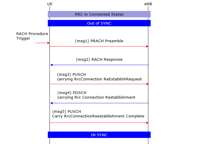
RACH Procedure on RRC Connection Re-establishment when Out-of-SyncThis scenario depicts the RACH Procedure for RRC Connection Re-establishment When Out-of-Sync. This process is triggered when a UE loses synchronization with the eNB and needs to re-establish its RRC connection.
Here is a step-by-step explanation of the procedure:
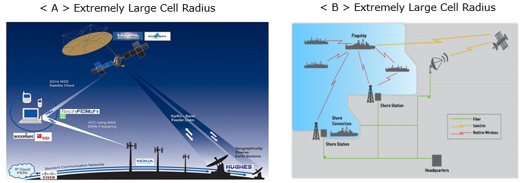
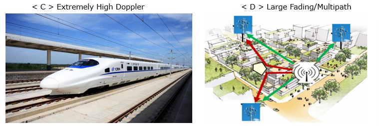
PRACH Optimization in Cell PlanningThis section would be the one you can apply all the knowledge of PRACH parameters you have learned. As any other theories in the text book, it is not always easy to digest and apply those parameters in real life cell design and parameter optimization. To be honest, I don't have any personal experience of applying those parameters in real life cell design and parameter optimization. Especially for this section, I got valuable advise from an expert (Jared Cho) and used his comments as a skelleton and I will keep adding as I learn more. Also, I am waiting for the comments/advise from the readers who has experiences/experties in this subject. My approach is to set a few extreme situations and identify what would be the dominant factors (parameters) in those situation. Following is several extreme cases that I could think of as of now (probably add more). First think of what kind of RACH parameters will be the dominant factors for each of these cases on your own.
< Cell Radius and Multi Path condition for different cell sites >
In Case < A> and < B >, the cell redius would be extremly large from a few tens of km even up to 100 km in extrem case. Even though the cell radius is very large in this case, the path between the transmitter and reciever tend to be line of sight. So, in this case I think Preamble format can be a dominant factors in terms of covering wide range and maximun TA (Timing Advanced) value in RAR can be the domant factor as well. Due to the long distance between UE and eNB, there tend to be wide range of timing delay. So TA range that can compensate those wide range of timing variation. In addition, to compensate the possible delay spread due to long traveling distance, N_CS (zeroCorrelationZoneConfig) would play an important role as well. The larger cell radius is, you may pick higher values for zeroCorrelationZoneConfig. For example, I was told that a cell can cover around 100 km with preamble format 1 and zeroCorrelationZoneConfig = 15
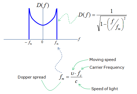
In Case < C > which is the case where High Speed Training model can apply. In this case, both UE and eNB can experience a large doppler shift (expecially when the train just passes eNB). In this case, turning on 'HighSpeedFlag' (i.e, HighSpeedFlag = True) would be important and selecting proper N_CS value depending on situation would be important. Since the doppler shift is a determining factors of parameter optimization, you may easily understand that not only the speed of the motion but also the carrier frequency will play the important role. As you know, Doppler shift is determined by both moving speed and Carrier Frequency as shown below.
Then you may ask exactly 'Is there any clear cut borderline between HighSpeedFlag=True and HighSpeedFlag=False in terms of Doppler Spread value ?'. I haven't found any document clearly defining on this. However, once you specify a certain doppler shift value as a borderline and you have a specific carrier frequency, you can easily figure out the speed limit for enabling/disabling the HighSpeedFlag. For example, if you set the doppler spread of 200 Hz as the border line, you can determine the speed limit as follows.
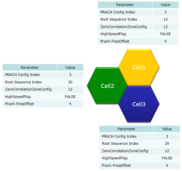
Now let's see an example showing the configuration of other PRACH parameters which is applicable in live network cell planning. I don't have personall experience with live network cell planning and Jared Cho happily contributed his experties here as well.
< Example of RACH Parameters of neighbouring cells >
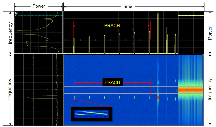
Let's take a look at some of the configurations set in this example. (In this example, it is assumed that the preamble format is set to be Format 0) First you would notice that all the cells has same PRACH config Index. Are these required to be same ? No, you configure them differently depending on situation. If you set them differently (especially in such a way that each of the cells receive PRACH at different subframes), it would be helpful to reduce any possible interference caused by PRACH for other cell. However, in this case a PRACH in one cell can cause interference to PUSCH in other cells. Second ZeroCorrelationZoneConfig is set to be same in this case. These are not required to be the same either. In this example, we assume that the radius of every cell is almost same. Considering that Preamble Format 0 has roughly 14 km, ZeroCorrelationZoneConfig is set to be 12 to match the coverage and Root Sequence Index for each cell is set with a certain interval (the interval of 10 in this case). Lastly prach-FrequencyOffset is set to be 4. This can be set as any possible value, but it is recommended that PRACH would not cause any interference with the location of PUCCH. PRACH RF SnapshotTo capture this spectrum, I configured the setup where UE failed to receive RAR from network for several times. As you see here, UE keep transmitting PRACH with the increment of power specified by powerRampingStep in SIB2 until it successfully detects RAR. It will keep retransmitting until the number of transmission hits preambleTransMax. The interval between a preamble and next preamble is determined by backoff indicator.
< PRACH on Spectrum Analyzer >
RACH in srsRANIf you are interested in real implementation of RACH procedure at source code level, following API in srsRAN can be a good reference.
3GPP Standard for RACH Process3GTS 36.300 (10.1.5) : Overall description of RACH Process. Read this first. 3GTS 36.211 (5.7) : RRC Messages and IE (Information Elements) which are involved in RACH process. 3GTS 36.213 (6) : MAC Layer Procedure related to RACH Process.
|
||||||||||||||||||||||||||||||||||||||||||||||||||||||||||||||||||||||||||||||||||||||||||||||||||||||||||||||||||||||||||||||||||||||||||||||||||||||||||||||||||||||||||||||||||||||||||||||||||||||||||||||||||||||||||||||||||||||||||||||||||||||||||||||||||||||||||||||||||||||||||||||||||||||||||||||||||||||||||||||||||||||||||||||||||||||||||||||||||||||