The meaning of "Envelop Tracking" in relation to Amplifier is simple and straightfoward. It means 'continuosly figuring out/detecting the evelope of the signal. The important thing is "Why do we need it ?".
The biggest motivation of the envelop tracking would be "to minimize the energy consumption to operate an amplifier" and this is especially important for mobile communication device. "Minimize the energy consumption" means "to provide the power in only the amount which is really needed by the amplifer". Using this technology wisely, we can also reduce the heat dissipated by the amplifier because the technology provide only the bare minimum energy and there are not so many engergy remaining to be dissipated as heat. What this mean is "If we have very well designed envelop tracking, we can solve the two biggest problems of all the power amplifier, i.e, energy consumption and heat dissipation".
Three questions follow from that. How much a fixed supply actually wastes, what a power supply has to be able to do to recover it, and what the technique costs in return. The sections below take them in that order, after the comparison the page already draws.
- What changes when the supply follows the signal ?
- Why does a fixed supply waste so much ?
- What does the supply modulator have to do ?
- What does envelope tracking cost ?
- Reference :
- YouTube
What changes when the supply follows the signal ?
The change is smaller than it looks, and the drawing below makes that easy to miss. Every block on the signal path stays where it was. What moves is where the amplifier gets its supply voltage from, and how fast that voltage is allowed to change.
It would be clearer if you compare the two cases with and without using this technology. These two cases can be illustrated as below.
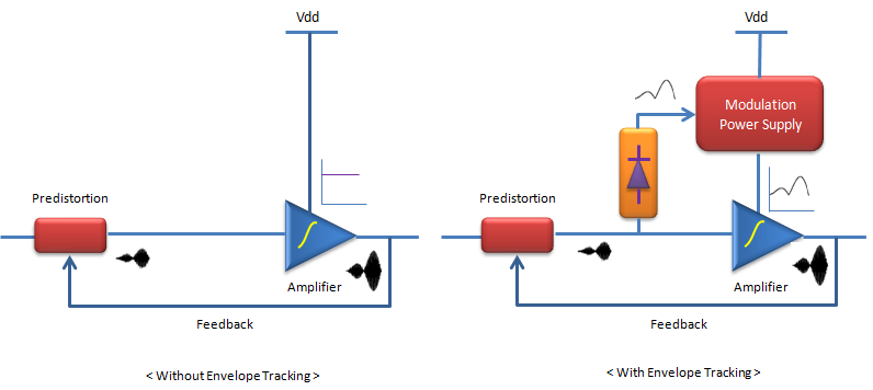
The diagram shown on the left shows the case which does not use 'envelop tracking'. In this case, a constant power (Vdd) is supplied to the amplifier and this constant power is normally set to be the maximum power for the amplifier operation. But in reality, the amplifier does not always need the maximum power. In the case, when the amplifier does not need the maximum power, there is remaining power which is not used by the amplifier and is dissipated as heat.
The diagram show on the right shows the case which use 'evelop tracking'. In this diagram, you see two additional components which is not shown in previous case. The envelop dector(yellow) is the part that detects the envelop of the incoming signal and the modulation power supply is the part that can change the output of the power supply at very fast rate. In this system, the 'envelop detector' detects the envelop of the incoming signal and feed the value to the modulation power supply. This 'envelop' represents the amount of the energy that is required for the amplifier at that specific moment and with the detected envelop value, the power supply can supply the (almost) exact amount of the energy that is needed by the amplifier for a specific moment and this process is performed at very fast rate. In this way, this system can minimize the amount of the energy that is wasted by the amplifier.
- Both panels carry the same signal path. A blue line runs from the left through the red
Predistortion block and past a small waveform. It then enters the blue triangle labelledAmplifier and leaves as a larger waveform on the right. - Both panels also carry the same
Feedback line. It leaves the amplifier output, runs back along the bottom, and arrives at the Predistortion block. - The argument sits in the two small inset plots beside the Vdd line. On the left the plot is a flat horizontal line. On the right it is a curve that rises and falls.
- The envelope detector is the orange block with the diode symbol inside it. It sits after Predistortion and before the Amplifier, and it taps the signal rather than interrupting it.
- The
Modulation Power Supply is the red block at the top right. Vdd arrives there instead of at the amplifier, and the block's output goes down to the supply pin that Vdd reached directly in the left panel.
Note : In the illustration shown above, you see a block labeled 'Predistortion', but I didn't explained anything about it because it is not the scope of this page. Refer to 'Predistortion' page if you want to know what it is.
One point about that block belongs here, because it explains why Predistortion appears in both panels rather than only in the right one. Predistortion is not part of envelope tracking. It linearises the amplifier in either design. Envelope tracking then gives it more work rather than less, and the last section on this page explains why.
Envelope tracking changes the supply and not the signal path : the amplifier, the predistorter and the feedback loop are identical in both panels of the drawing.Two blocks are added and one connection is rerouted : an envelope detector taps the signal, and a modulation power supply stands between Vdd and the amplifier.The inset plots are the whole difference : flat on the left and varying on the right, which is what a tracking supply means in one picture.
Why does a fixed supply waste so much ?
The waste is not a small correction at the edges. A modern radio signal spends most of its time well below its own peak, while a fixed supply has to be set for that peak. The gap between the two is what makes envelope tracking worth building.
The reason starts with the modulation rather than with the amplifier. A constant envelope signal such as GSM lets a designer run the amplifier saturated, where it is at its most efficient. Chen's thesis lists what replaced that: NADC, EDGE, IS-95 CDMA, W-CDMA, 802.11 WLAN and 802.16 WiMax all carry a non-constant envelope. An amplifier for those has to work in its linear region.
Linear operation is only half the cost. The same thesis adds that such an amplifier must also be backed off by the peak-to-average ratio, which reduces the efficiency further. Wang and colleagues give a number for that ratio in one case. An 802.11g signal carries 64-QAM across 52 OFDM carriers, and its envelope peak-to-average ratio is 8 to 10 dB.
Eight decibels is a factor of about six in power. The amplifier is therefore sized for a condition it meets rarely, and the supply is sized with it. Wang's paper states the consequence in one line. Backing off lowers efficiency significantly for high peak-to-average signals, and that is the inherent trade-off between linearity and efficiency in amplifier design.
Figure 1 draws the same comparison as a waveform instead of as a block diagram. Both panels plot one identical envelope. Only the supply rail above it differs, and the shaded band between rail and envelope is voltage the amplifier never delivers to the antenna.
Figure 1. Where the unused voltage goes. The rail on the left is fixed at the peak of the envelope, so the shaded band stays wide almost all of the time. The rail on the right holds a constant headroom above the same envelope, and the band shrinks to that headroom. The waveform is drawn to illustrate the comparison and is not a measurement.
- The envelope is the same curve in both panels. Nothing about the signal changed between them.
- The left rail sits at the peak, because a fixed supply has to survive the worst moment the signal will ever produce.
- The right rail holds a small constant gap above the envelope. That gap is the headroom, and the section after this one explains why it cannot be zero.
- The shaded band is voltage dropped inside the amplifier rather than delivered to the antenna. It is what the opening of this page calls remaining power which is not used by the amplifier and is dissipated as heat.
The problem is the modulation and not the amplifier : a non-constant envelope forces linear operation and a back-off equal to the peak-to-average ratio.The peak-to-average ratio sets how much there is to recover : Wang reports 8 to 10 dB for an 802.11g OFDM signal, and the supply is sized for a peak the signal rarely reaches.Linearity and efficiency trade against each other : backing off buys linearity and pays in efficiency, and that is the trade envelope tracking exists to reduce.
What does the supply modulator have to do ?
This is where the idea becomes hard to build. Envelope tracking needs a power supply that can change its output as fast as the signal changes. That demands far more bandwidth than the channel itself occupies.
The envelope is not a filtered copy of the signal. Chen's thesis writes it as the square root of I2 plus Q2, and points out that this is a nonlinear transformation of I and Q. A nonlinear transformation does not preserve bandwidth. The thesis states the result directly: the envelope has a wider bandwidth than the original signal, and it is not band-limited at all.
That is why the numbers in the literature are multiples rather than equalities. The thesis quotes one source recommending a supply circuit bandwidth of three times the RF bandwidth for a carrier to interference ratio better than 40 dBc. It quotes another giving four times the carrier bandwidth for CDMA and W-CDMA, and adding that the supply switching frequency should be at least five times that bandwidth.
Follow those multiples through for W-CDMA and the difficulty becomes concrete. The carrier is 3.84 MHz wide, four times that is 15.36 MHz, and five times again is 76.8 MHz. Chen's thesis reports exactly that number and calls it very hard to implement efficiently.
The same thesis records where the technique had actually been made to work. Closed loop implementations had been limited to narrow standards, NADC at 30 kHz and EDGE at 200 kHz. For a 3.84 MHz W-CDMA channel, it says, those conservative design practices become unrealistic. That sentence is the reason envelope tracking took so long to reach a handset.
Detector bandwidth also decides which kind of envelope tracking a design is, and Wang's paper turns that into a definition. Where the amplitude detector responds only to the long term average of the envelope, the result is average envelope tracking. Where it follows the instantaneous variations, the result is wideband envelope tracking. One block diagram covers both, and only the bandwidth separates them.
Average envelope tracking is the easier of the two to build. It fits a system that already controls transmit power, and Wang's paper names the CDMA reverse link as that case. The supply then moves only as fast as the power control loop, which is far slower than the modulation.
The envelope is wider than the signal that produced it : it is the square root of I2 plus Q2, a nonlinear transformation, so it is not band-limited.The supply bandwidth is a multiple of the channel bandwidth : three to four times is quoted, with a switching frequency of five times that again.W-CDMA is the case that made this difficult : 3.84 MHz becomes a 76.8 MHz switching requirement, which Chen's thesis calls very hard to implement efficiently.Detector bandwidth names the technique : a slow detector gives average envelope tracking and a fast one gives wideband envelope tracking, from the same block diagram.
What does envelope tracking cost ?
None of this is free, and the block diagram does not show the price. A tracking supply brings three costs. The amplifier loses output capability, its gain stops being constant, and two signal paths must now agree in time.
The headroom in Figure 1 is the first cost. Chen's thesis states both halves of it. The supply voltage is varied with sufficient headroom to minimize distortion, and that headroom also reduces the power output capability of the amplifier. The rail cannot sit on the envelope, so the headroom is a deliberate loss.
The second cost explains the Predistortion block that the note above sets aside. In an envelope tracking amplifier the gain falls as the supply voltage falls. Chen's thesis names that gain variation as a source of nonlinearity, for high peak-to-average signals and for wide power control ranges. Predistortion is one of the fixes it records against the effect. The block sits in both panels of the drawing, and a tracking supply gives it more to correct.
The third cost is timing. Two paths now carry the same information, the radio path and the envelope path, and they have to arrive together. Wang and colleagues spend most of their paper on it. An envelope tracking amplifier turns out to be significantly less sensitive to that misalignment than the older envelope elimination and restoration approach. They call that a crucial benefit for wide bandwidth operation.
That comparison is worth spelling out, because the two techniques are usually named together. Envelope elimination and restoration splits the signal into a phase path and an amplitude path, amplifies the phase path with a saturated amplifier, and restores the amplitude through the supply. Envelope tracking, in Chen's words, is a simplification of it. Only the envelope is extracted, the radio signal is never decomposed, and the amplifier stays in its linear region. The price is the lower efficiency of linear operation, and the reward is that delay matching is not as crucial.
Wang's measured result gives a sense of what a complete system reached. Their wideband envelope tracking amplifier achieved a peak drain efficiency of 30 percent at 20 dBm output, on a 2.4 GHz OFDM signal. That is a 2005 result for 802.11g rather than a figure to quote for a modern handset, and it is given here as what that paper measured.
Headroom is saving that is deliberately not taken : the rail stays above the envelope, and holding it there also lowers the amplifier's output capability.A moving supply moves the gain with it : the resulting nonlinearity is what predistortion absorbs, in both halves of the drawing above.Two paths now have to agree in time : envelope tracking tolerates misalignment far better than envelope elimination and restoration, which is why it is the one that reached wide bandwidth signals.The efficiency is bought rather than given : Wang's complete system measured 30 percent peak drain efficiency at 20 dBm on a 2.4 GHz OFDM signal in 2005.
Reference :
[2] WIDEBAND DYNAMIC BIASING OF POWER AMPLIFIERS FOR WIRELESS HANDHELD APPLICATIONS (Jau-Horng Chen)
[3] Solutions and Measurement Tools for Use in Average Power and Envelope Tracking Design
[4] Simulating Envelope Tracking with Agilent Advanced Design System
[5] Envelope Tracking for Cellular RF Power Amplifiers