Matlab Toolbox - 4G/LTE
PBCH
If you don't know what PBCH(Physical BroadCasting Channel) is, refer to Physical Layer Channel : Downlink : PBCH (Physical Broadcasting Channel) page first.
< Generating BCH bit sequence >
% First you have to define properites of a eNodeB.
% NDLRB indicate System Bandwith in the unit of RBs.
% NDLRB 6 = 1.4 Mhz, NDLRB 15 = 3.0 Mhz, NDLRB 25 = 5.0 Mhz,
% NDLRB 50 = 10 Mhz, NDLRB 75 = 15 Mhz, NDLRB 100 = 20 Mhz
% CellRefP indicate number of downlink Antenna. CellRefP = 1 means 1 transmission antenna (SISO)
% NCellID indicate PCI (Physical Channel Identity) of the Cell
% NSubframe indicate the subframe number.
enb.CyclicPrefix = 'Normal';
enb.PHICHDuration = 'Normal';
enb.Ng = 'Sixth';
enb.NDLRB = 6;
enb.CellRefP = 1;
enb.DuplexMode = 'FDD';
enb.NCellID = 1;
enb.NSubframe = 0;
enb.CFI = 1;
enb.NFrame = 0;
% Now you have to generate MIB bits. This is basically the bit string that you can see from ASN Decoder.
% If you pass eNodeB information into lteMIB() function, it will generate MIB bits based on the information
% configured in enb.
mib_bits = lteMIB(enb);
% Next step is to apply the channel coding process to the MIB bits (a kind of user data).
% This is done by lteBCH()
% as shown below. Basically this performs step (1)~(3) of procedures descringed in
% PBCH (Physical Broadcasting Channel)
bch_cw = lteBCH(enb,mib_bits);
% Now I want to show you the two sets of data generated above into a plot.
% this plot does not have any physical meaning since it is just user data and channel coding process
% but it would be easiler to see overall meaning rather than looking at all the ones and zeros.
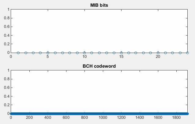
% this is the plot to show the MIB message itself. It is just layer 3 bits.
subplot(2,1,1);
stem(mib_bits); xlim([0 length(mib_bits)]); ylim([0 1]);
title('MIB bits');
% this is the plot to show the result of channel coding (the result of lteBCH()).
subplot(2,1,2);
stem(bch_cw); xlim([0 length(bch_cw)]); ylim([0 1]);
title('BCH codeword');
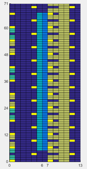
The first example show the case of MIB message with System BW = 1.4 Mhz and Frame Number = 0. As you see, all zeros in layer 0 message and all 0 even after the channel coding.
One possible motivation from this example would be just to have 'question' (no need to have answer yet) how the small number of bits can get converted into such a long/huge number of bits (over 1800 bits).
|
enb.PHICHDuration = 'Normal'; enb.Ng = 'Sixth'; enb.NDLRB = 6; enb.CellRefP = 1;
enb.NCellID = 1; enb.NSubframe = 0; enb.NFrame = 0; |
|
|
|
|
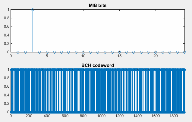
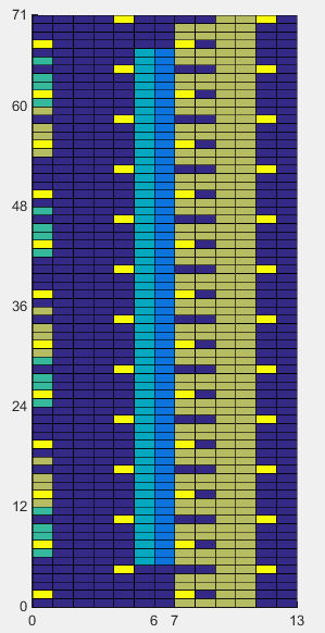
This example is almost same as previous example. the only difference is the channel bandwidth. I used 3.0 Mhz Bandwidth and it sets only one bit to be '1'. As you see in the second graph (the output of channel coding), you would see much more complicated patterns of ones and zeros. Why ? Just have a question is enough.
|
enb.PHICHDuration = 'Normal'; enb.Ng = 'Sixth'; enb.NDLRB = 15; enb.CellRefP = 1;
enb.NCellID = 1; enb.NSubframe = 0; enb.NFrame = 0; |
|
|
|
|
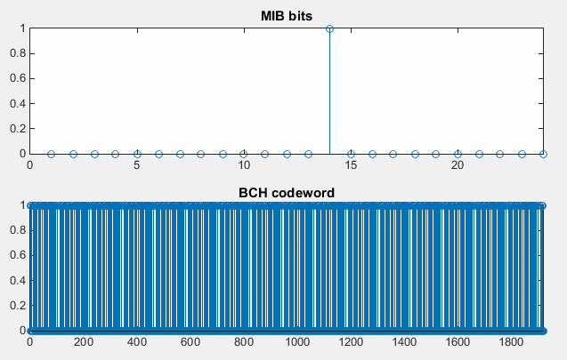
Following is for the case which is same as the first example except NFrame (SFN). I guess you would see the difference.
If you have LteToolbox, Try enb.NFrame = 1,2,3 and see what you get ? Are they all the same ? or different ?
If they are all same, would you be able to explain why ?
|
enb.PHICHDuration = 'Normal'; enb.Ng = 'Sixth'; enb.NDLRB = 15; enb.CellRefP = 1;
enb.NCellID = 1; enb.NSubframe = 0; enb.NFrame = 4; |
|
|
|
|
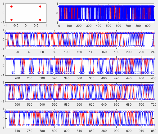
< Generating PBCH Symbol Data >
In this section, we will convert the encoded BCH data into physical layer symbols and plot them into constellation and sequence plot.
% First you have to define properites of a eNodeB.
% NDLRB indicate System Bandwith in the unit of RBs.
% NDLRB 6 = 1.4 Mhz, NDLRB 15 = 3.0 Mhz, NDLRB 25 = 5.0 Mhz,
% NDLRB 50 = 10 Mhz, NDLRB 75 = 15 Mhz, NDLRB 100 = 20 Mhz
% CellRefP indicate number of downlink Antenna. CellRefP = 1 means 1 transmission antenna (SISO)
% NCellID indicate PCI (Physical Channel Identity) of the Cell
% NSubframe indicate the subframe number.
enb.CyclicPrefix = 'Normal';
enb.PHICHDuration = 'Normal';
enb.Ng = 'Sixth';
enb.NDLRB = 6;
enb.CellRefP = 1;
enb.DuplexMode = 'FDD';
enb.NCellID = 0;
enb.NSubframe = 0;
enb.CFI = 1;
enb.NFrame = 0;
% Now you have to generate MIB bits. This is basically the bit string that you can see from ASN Decoder.
% If you pass eNodeB information into lteMIB() function, it will generate MIB bits based on the information
% configured in enb.
mib_bits = lteMIB(enb);
% Next step is to apply the channel coding process to the MIB bits (a kind of user data).
% This is done by lteBCH()
% as shown below. Basically this performs step (1)~(3) of procedures descringed in
% PBCH (Physical Broadcasting Channel)
bch_cw = lteBCH(enb,mib_bits);
% Now if you pass the encoded BCH bit stream into ltePBCH, it will generate physical layer symbols for BCH
%,which is PBCH symbol.
pbch_sym = ltePBCH(enb,bch_cw);
pbch_sym_arrayIndex = 0:length(pbch_sym)-1;
pbch_sym_ind = ltePBCHIndices(enb,{'1based','re'});
% Now I will create a bunch of graphs showing different aspects of the PBCH symbols.
% The first two plot shows whole PBCH symbols in a single plot. The plot on top left will show you the
% constellation of the whole PBCH symbols generated above.
% The plot on the top right show you the whole PBCH symbols in sequence number (just the index of the array)
subplot(5,3,1);
plot(real(pbch_sym),imag(pbch_sym),'ro','MarkerFaceColor',[1 0 0]);
axis([-1 1 -1 1]);
subplot(5,3,[2 3]);
plot(pbch_sym_arrayIndex,real(pbch_sym),'ro-',pbch_sym_arrayIndex,imag(pbch_sym),'bo-');
xlim([0 max(pbch_sym_arrayIndex)]);ylim([-1 1]);
% Then, I split the generated symbols into 4 clusters, each of them has 240 symbols and plot the four clusters
% onto separate graph. Why did I split into 4 clusters ? What would be the meaning of the each cluster ?
% see SIB Scheduling page.
subplot(5,3,[4 6]);
plot_index = 1:240;
plot(plot_index,real(pbch_sym(plot_index)),'ro-',plot_index,imag(pbch_sym(plot_index)),'bo-');
xlim([min(plot_index) max(plot_index)]);ylim([-1 1]);
subplot(5,3,[7 9]);
plot_index = 241:480;
plot(plot_index,real(pbch_sym(plot_index)),'ro-',plot_index,imag(pbch_sym(plot_index)),'bo-');
xlim([min(plot_index) max(plot_index)]);ylim([-1 1]);
subplot(5,3,[10 12]);
plot_index = 481:720;
plot(plot_index,real(pbch_sym(plot_index)),'ro-',plot_index,imag(pbch_sym(plot_index)),'bo-');
xlim([min(plot_index) max(plot_index)]);ylim([-1 1]);
subplot(5,3,[13 15]);
plot_index = 721:960;
plot(plot_index,real(pbch_sym(plot_index)),'ro-',plot_index,imag(pbch_sym(plot_index)),'bo-');
xlim([min(plot_index) max(plot_index)]);ylim([-1 1]);
|
enb.PHICHDuration = 'Normal'; enb.Ng = 'Sixth'; enb.NDLRB = 6; enb.CellRefP = 1;
enb.NCellID = 1; enb.NSubframe = 0; enb.NFrame = 0; |
|
|
|
|
< PBCH RE Mapping>
In this step, I will show the Resource Elements that will carry the PBCH symbols generated at previous step.
% First you have to define properites of a eNodeB.
% NDLRB indicate System Bandwith in the unit of RBs.
% NDLRB 6 = 1.4 Mhz, NDLRB 15 = 3.0 Mhz, NDLRB 25 = 5.0 Mhz,
% NDLRB 50 = 10 Mhz, NDLRB 75 = 15 Mhz, NDLRB 100 = 20 Mhz
% CellRefP indicate number of downlink Antenna. CellRefP = 1 means 1 transmission antenna (SISO)
% NCellID indicate PCI (Physical Channel Identity) of the Cell
% NSubframe indicate the subframe number.
enb.CyclicPrefix = 'Normal';
enb.PHICHDuration = 'Normal';
enb.Ng = 'Sixth';
enb.NDLRB = 6;
enb.CellRefP = 1;
enb.DuplexMode = 'FDD';
enb.NCellID = 0;
enb.NSubframe = 0;
enb.CFI = 1;
enb.NFrame = 0;
% following is PHICH parameters that will be used ltePHICH() function in later step.
PHICH_Group_Index = 0;
PHICH_Sequence_Index = 1;
HARQ_Indicator_Value = 0; % 0 = NACK, 1 = ACK
% Following is to create an empty resource grid for one subframe.
resourceGrid = lteDLResourceGrid(enb);
% Following is to create symbols for Cell Specific Reference Signal and make a list of resource index for the
% reference signal.
rsAnt0 = lteCellRS(enb,0);
indAnt0 = lteCellRSIndices(enb,0);
resourceGrid(indAnt0) = rsAnt0;
% Following is to create symbols for PCFICH and make a list of resource index for the signal
cfi_cw = lteCFI(enb);
pcfich_sym = ltePCFICH(enb,cfi_cw);
pcfich_sym_arrayIndex = 0:length(pcfich_sym)-1;
pcfich_sym_ind = ltePCFICHIndices(enb,{'1based','re'});
% Following is to create symbols for PBCH and make a list of resource index for the signal (channel)
mib_bits = lteMIB(enb);
bch_cw = lteBCH(enb,mib_bits);
pbch_sym = ltePBCH(enb,bch_cw);
pbch_sym_arrayIndex = 0:length(pbch_sym)-1;
pbch_sym_ind = ltePBCHIndices(enb,{'1based','re'});
% Following is to create symbols for PSS and make a list of resource index for the signal
pss = ltePSS(enb);
pss_arrayIndex = 0:length(pss)-1;
pss_sym_ind = ltePSSIndices(enb,0,{'1based','re'});
% Following is to create symbols for SSS and make a list of resource index for the signal
sss = lteSSS(enb);
sss_arrayIndex = 0:length(sss)-1;
sss_sym_ind = lteSSSIndices(enb,0,{'1based','re'});
% Following is to create symbols for PHICH and make a list of resource index for the signal
phich_sym = ltePHICH(enb,[PHICH_Group_Index,PHICH_Sequence_Index,HARQ_Indicator_Value]);
phich_sym_arrayIndex = 0:length(phich_sym)-1;
phich_sym_ind = ltePHICHIndices(enb,{'1based','re'});
% Following part is filling the resource grid with each of the signal.. but if you see carefully I didn't fill this
% with real symbol number, I just filled it with a constant that I arbitrarily set. This is just for visualization..
% just to allocate constant/outstanding color for each signal. When you use this resource grid for real
% transmission (not for visualization), fill the resourceGrid with real symbol value you generated above.
pss_scale = 0.2;
sss_scale = 0.4;
phich_scale = 0.7;
pcfich_scale = 0.5;
pbch_scale = 0.7;
resourceGrid(pss_sym_ind) = pss_scale;
resourceGrid(sss_sym_ind) = sss_scale;
resourceGrid(pcfich_sym_ind) = pcfich_scale;
resourceGrid(phich_sym_ind) = phich_scale;
resourceGrid(pbch_sym_ind) = pbch_scale;
% Following is to display the resource grid. I didn't find any proper functions in the toolbox to display
% one subframe grid as I like. So I used a little bit of tricks. First I plot 3D surface graph with the grid and
% move the view point right on top of the plot so that it looks like plane 2D grid.
xStep = 0:13;
yStep = 0:(enb.NDLRB*12-1);
surface(xStep,yStep,abs(resourceGrid));
axis([0 13 0 (enb.NDLRB*12-1) 0 1]);
view([0,90]);
set(gca,'xtick',[0 6 7 13]);
set(gca,'ytick',[[0:12:enb.NDLRB*12-1] [enb.NDLRB*12-1]]);
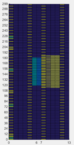
The first set of examples shows the location of PBCH Resource Elements in 1.4 Mhz BW. The light green REs in the symbol 7~10 represents PBCH. Can you count how many Resource Elements are for PBCH ? Maybe a little confusing to count, but it should be 240 REs, meaning it should carry 240 symbols.
|
enb.PHICHDuration = 'Normal'; enb.Ng = 'Sixth'; enb.NDLRB = 6; enb.CellRefP = 1; enb.DuplexMode = 'FDD';
enb.NCellID = 0; enb.NSubframe = 0; enb.CFI = 1; enb.NFrame = 0;
PHICH_Group_Index = 0; PHICH_Sequence_Index = 1; HARQ_Indicator_Value = 0; % 0 = NACK, 1 = ACK
|
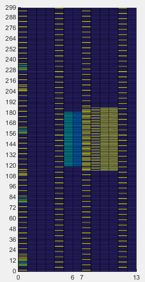
enb.PHICHDuration = 'Normal'; enb.Ng = 'Sixth'; enb.NDLRB = 6; enb.CellRefP = 1; enb.DuplexMode = 'FDD';
enb.NCellID = 1; enb.NSubframe = 0; enb.CFI = 1; enb.NFrame = 0;
PHICH_Group_Index = 0; PHICH_Sequence_Index = 1; HARQ_Indicator_Value = 0; % 0 = NACK, 1 = ACK |
|
|
|
The first set of examples shows the location of PBCH Resource Elements in 5 Mhz BW. The light green REs in the symbol 7~10 represents PBCH. Can you count how many Resource Elements are for PBCH ? Maybe a little confusing to count, but it should be 240 REs, meaning it should carry 240 symbols. Number of REs stay same regardless of system bandwidth.
|
enb.PHICHDuration = 'Normal'; enb.Ng = 'Sixth'; enb.NDLRB = 25; enb.CellRefP = 1; enb.DuplexMode = 'FDD';
enb.NCellID = 0; enb.NSubframe = 0; enb.CFI = 1; enb.NFrame = 0;
PHICH_Group_Index = 0; PHICH_Sequence_Index = 1; HARQ_Indicator_Value = 0; % 0 = NACK, 1 = ACK
|
enb.PHICHDuration = 'Normal'; enb.Ng = 'Sixth'; enb.NDLRB = 25; enb.CellRefP = 1; enb.DuplexMode = 'FDD';
enb.NCellID = 1; enb.NSubframe = 0; enb.CFI = 1; enb.NFrame = 0;
PHICH_Group_Index = 0; PHICH_Sequence_Index = 1; HARQ_Indicator_Value = 0; % 0 = NACK, 1 = ACK |
|
|
|
Appendix - A : Numerical Output for Encoding Process
enb.CyclicPrefix = 'Normal';
enb.PHICHDuration = 'Normal';
enb.Ng = 'Sixth';
enb.NDLRB = 6;
enb.CellRefP = 1;
enb.DuplexMode = 'FDD';
enb.NCellID = 0;
enb.NSubframe = 0;
enb.CFI = 1;
enb.NFrame = 4;
mib_bits = lteMIB(enb);
bch_cw = lteBCH(enb,mib_bits);
mib_bits_crc = lteCRCEncode(mib_bits,'16',0);
bch_Econde = lteConvolutionalEncode(mib_bits_crc);
bch_Econde_RM = lteRateMatchConvolutional(bch_Econde,length(bch_cw));
isequal(bch_cw,bch_Econde_RM)
|
enb.PHICHDuration = 'Normal'; enb.Ng = 'Sixth'; enb.NDLRB = 6; enb.CellRefP = 1;
enb.NCellID = 0; enb.NSubframe = 0; enb.CFI = 1; enb.NFrame = 4; |
|
|
mib_bits' (24 bits) 0 0 0 0 0 0 0 0 0 0 0 0 0 1 0 0 0 0 0 0 0 0 0 0 mib_bits_crc' (40 bits = 24 + 16) 0 0 0 0 0 0 0 0 0 0 0 0 0 1 0 0 0 0 0 0 0 0 0 0 1 1 0 0 1 1 0 0 1 1 0 0 0 1 0 0 bch_Econde' (120 bits = ( 24 + 16 ) x 3)
1 0 1 1 0 0 0 0 0 0 0 0 0 1 0 1 1 0 1 1 0 0 0 0 1 1 1 0 0 0 1 1 0 0 1 1 1 0 0 0 1 0 0 1 0 0 0 0 0 0 0 0 0 1 1 1 1 0 0 1 0 0 0 0 1 0 0 0 0 0 1 1 0 0 1 1 1 1 0 0 0 1 0 1 0 0 0 0 0 0 0 0 0 1 1 1 0 1 0 1 0 0 0 0 1 0 0 1 0 1 1 0 0 1 1 0 1 0 0 0
bch_Econde_RM' (1920 bits)
0 1 0 0 0 1 0 0 0 0 0 0 1 1 1 1 1 0 0 0 0 1 1 1 0 0 0 0 0 1 0 1 1 1 1 0 1 0 0 0 0 0 0 0 0 1 0 0 0 1 0 0 1 1 1 1 1 0 0 0 0 1 1 1 0 0 0 0 0 1 0 0 0 0 1 1 1 0 0 0 0 0 1 1 1 1 1 0 0 0 0 1 1 1 0 1 0 0 0 0 0 1 0 0 0 0 0 0 0 1 0 0 0 0 1 1 1 0 0 0 0 1 0 0 0 1 0 0 0 0 0 0 1 1 1 1 1 0 0 0 0 1 1 1 0 0 0 0 0 1 0 1 1 1 1 0 1 0 0 0 0 0 0 0 0 1 0 0 0 1 0 0 1 1 1 1 1 0 0 0 0 1 1 1 0 0 0 0 0 1 0 0 0 0 1 1 1 0 0 0 0 0 1 1 1 1 1 0 0 0 0 1 1 1 0 1 0 0 0 0 0 1 0 0 0 0 0 0 0 1 0 0 0 0 1 1 1 0 0 0 0 1 0 0 0 1 0 0 0 0 0 0 1 1 1 1 1 0 0 0 0 1 1 1 0 0 0 0 0 1 0 1 1 1 1 0 1 0 0 0 0 0 0 0 0 1 0 0 0 1 0 0 1 1 1 1 1 0 0 0 0 1 1 1 0 0 0 0 0 1 0 0 0 0 1 1 1 0 0 0 0 0 1 1 1 1 1 0 0 0 0 1 1 1 0 1 0 0 0 0 0 1 0 0 0 0 0 0 0 1 0 0 0 0 1 1 1 0 0 0 0 1 0 0 0 1 0 0 0 0 0 0 1 1 1 1 1 0 0 0 0 1 1 1 0 0 0 0 0 1 0 1 1 1 1 0 1 0 0 0 0 0 0 0 0 1 0 0 0 1 0 0 1 1 1 1 1 0 0 0 0 1 1 1 0 0 0 0 0 1 0 0 0 0 1 1 1 0 0 0 0 0 1 1 1 1 1 0 0 0 0 1 1 1 0 1 0 0 0 0 0 1 0 0 0 0 0 0 0 1 0 0 0 0 1 1 1 0 0 0 0 1 0 0 0 1 0 0 0 0 0 0 1 1 1 1 1 0 0 0 0 1 1 1 0 0 0 0 0 1 0 1 1 1 1 0 1 0 0 0 0 0 0 0 0 1 0 0 0 1 0 0 1 1 1 1 1 0 0 0 0 1 1 1 0 0 0 0 0 1 0 0 0 0 1 1 1 0 0 0 0 0 1 1 1 1 1 0 0 0 0 1 1 1 0 1 0 0 0 0 0 1 0 0 0 0 0 0 0 1 0 0 0 0 1 1 1 0 0 0 0 1 0 0 0 1 0 0 0 0 0 0 1 1 1 1 1 0 0 0 0 1 1 1 0 0 0 0 0 1 0 1 1 1 1 0 1 0 0 0 0 0 0 0 0 1 0 0 0 1 0 0 1 1 1 1 1 0 0 0 0 1 1 1 0 0 0 0 0 1 0 0 0 0 1 1 1 0 0 0 0 0 1 1 1 1 1 0 0 0 0 1 1 1 0 1 0 0 0 0 0 1 0 0 0 0 0 0 0 1 0 0 0 0 1 1 1 0 0 0 0 1 0 0 0 1 0 0 0 0 0 0 1 1 1 1 1 0 0 0 0 1 1 1 0 0 0 0 0 1 0 1 1 1 1 0 1 0 0 0 0 0 0 0 0 1 0 0 0 1 0 0 1 1 1 1 1 0 0 0 0 1 1 1 0 0 0 0 0 1 0 0 0 0 1 1 1 0 0 0 0 0 1 1 1 1 1 0 0 0 0 1 1 1 0 1 0 0 0 0 0 1 0 0 0 0 0 0 0 1 0 0 0 0 1 1 1 0 0 0 0 1 0 0 0 1 0 0 0 0 0 0 1 1 1 1 1 0 0 0 0 1 1 1 0 0 0 0 0 1 0 1 1 1 1 0 1 0 0 0 0 0 0 0 0 1 0 0 0 1 0 0 1 1 1 1 1 0 0 0 0 1 1 1 0 0 0 0 0 1 0 0 0 0 1 1 1 0 0 0 0 0 1 1 1 1 1 0 0 0 0 1 1 1 0 1 0 0 0 0 0 1 0 0 0 0 0 0 0 1 0 0 0 0 1 1 1 0 0 0 0 1 0 0 0 1 0 0 0 0 0 0 1 1 1 1 1 0 0 0 0 1 1 1 0 0 0 0 0 1 0 1 1 1 1 0 1 0 0 0 0 0 0 0 0 1 0 0 0 1 0 0 1 1 1 1 1 0 0 0 0 1 1 1 0 0 0 0 0 1 0 0 0 0 1 1 1 0 0 0 0 0 1 1 1 1 1 0 0 0 0 1 1 1 0 1 0 0 0 0 0 1 0 0 0 0 0 0 0 1 0 0 0 0 1 1 1 0 0 0 0 1 0 0 0 1 0 0 0 0 0 0 1 1 1 1 1 0 0 0 0 1 1 1 0 0 0 0 0 1 0 1 1 1 1 0 1 0 0 0 0 0 0 0 0 1 0 0 0 1 0 0 1 1 1 1 1 0 0 0 0 1 1 1 0 0 0 0 0 1 0 0 0 0 1 1 1 0 0 0 0 0 1 1 1 1 1 0 0 0 0 1 1 1 0 1 0 0 0 0 0 1 0 0 0 0 0 0 0 1 0 0 0 0 1 1 1 0 0 0 0 1 0 0 0 1 0 0 0 0 0 0 1 1 1 1 1 0 0 0 0 1 1 1 0 0 0 0 0 1 0 1 1 1 1 0 1 0 0 0 0 0 0 0 0 1 0 0 0 1 0 0 1 1 1 1 1 0 0 0 0 1 1 1 0 0 0 0 0 1 0 0 0 0 1 1 1 0 0 0 0 0 1 1 1 1 1 0 0 0 0 1 1 1 0 1 0 0 0 0 0 1 0 0 0 0 0 0 0 1 0 0 0 0 1 1 1 0 0 0 0 1 0 0 0 1 0 0 0 0 0 0 1 1 1 1 1 0 0 0 0 1 1 1 0 0 0 0 0 1 0 1 1 1 1 0 1 0 0 0 0 0 0 0 0 1 0 0 0 1 0 0 1 1 1 1 1 0 0 0 0 1 1 1 0 0 0 0 0 1 0 0 0 0 1 1 1 0 0 0 0 0 1 1 1 1 1 0 0 0 0 1 1 1 0 1 0 0 0 0 0 1 0 0 0 0 0 0 0 1 0 0 0 0 1 1 1 0 0 0 0 1 0 0 0 1 0 0 0 0 0 0 1 1 1 1 1 0 0 0 0 1 1 1 0 0 0 0 0 1 0 1 1 1 1 0 1 0 0 0 0 0 0 0 0 1 0 0 0 1 0 0 1 1 1 1 1 0 0 0 0 1 1 1 0 0 0 0 0 1 0 0 0 0 1 1 1 0 0 0 0 0 1 1 1 1 1 0 0 0 0 1 1 1 0 1 0 0 0 0 0 1 0 0 0 0 0 0 0 1 0 0 0 0 1 1 1 0 0 0 0 1 0 0 0 1 0 0 0 0 0 0 1 1 1 1 1 0 0 0 0 1 1 1 0 0 0 0 0 1 0 1 1 1 1 0 1 0 0 0 0 0 0 0 0 1 0 0 0 1 0 0 1 1 1 1 1 0 0 0 0 1 1 1 0 0 0 0 0 1 0 0 0 0 1 1 1 0 0 0 0 0 1 1 1 1 1 0 0 0 0 1 1 1 0 1 0 0 0 0 0 1 0 0 0 0 0 0 0 1 0 0 0 0 1 1 1 0 0 0 0 1 0 0 0 1 0 0 0 0 0 0 1 1 1 1 1 0 0 0 0 1 1 1 0 0 0 0 0 1 0 1 1 1 1 0 1 0 0 0 0 0 0 0 0 1 0 0 0 1 0 0 1 1 1 1 1 0 0 0 0 1 1 1 0 0 0 0 0 1 0 0 0 0 1 1 1 0 0 0 0 0 1 1 1 1 1 0 0 0 0 1 1 1 0 1 0 0 0 0 0 1 0 0 0 0 0 0 0 1 0 0 0 0 1 1 1 0 0 0 0 1 0 0 0 1 0 0 0 0 0 0 1 1 1 1 1 0 0 0 0 1 1 1 0 0 0 0 0 1 0 1 1 1 1 0 1 0 0 0 0 0 0 0 0 1 0 0 0 1 0 0 1 1 1 1 1 0 0 0 0 1 1 1 0 0 0 0 0 1 0 0 0 0 1 1 1 0 0 0 0 0 1 1 1 1 1 0 0 0 0 1 1 1 0 1 0 0 0 0 0 1 0 0 0 0 0 0 0 1 0 0 0 0 1 1 1 0 0 0 |
|
Disclaimer ! :
This page is only to show you the overall logics and visualization for various LTE physical layer channels. I haven't investigated much about verifying about the accuracy.
If you think the code is not so efficient, it is 100% my fault. I haven't made any effort for effiecient code. I just tried to create code as simple as possible for the readers. As you know, easy-to-read code is not always efficient for a specific chipset.
If you find any mistake in terms of accuracy, it is also very highly likely be my fault. Not the problem of Matlab tool box itself.
Any comment and corrections if you find any mistake will be welcome and appreciated.