|
|
||
|
PBCH is a special channel to carry MIB and has following characteristics :
Followings are the topics that will be described in this page.
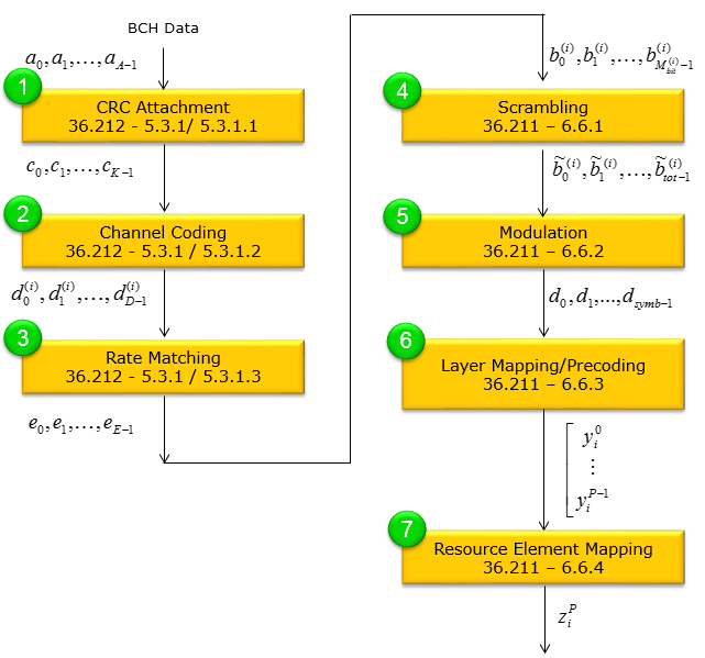
BCH Physical Layer ProcessingIn terms of data processing, it goes through the following steps. If you are seriously intersted in physical layer channel processing but PDSCH is too complicated for you to start, try following through each and every steps of PBCH processing as shown below and refer to 3GPP specification over and over whenever you have time. Refer to Precoding page for step (6). If you are also interested more in Step (6) in terms of Antenna Configuration, Refer to PHY Processing page. If you want to have more concrete implementation of this process, you may refer to Matlab :ToolBox : LTE : Downlink : PBCH
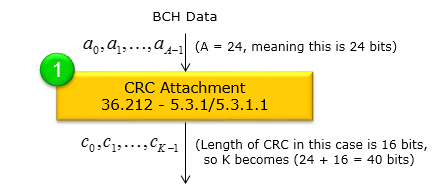
CRC Attachement : 36.212-5.3.1This is the step where CRC(Cyclic Redundancy Check) is attached to BCH (Broadcast Channel) transport block. The brief summary of this process is :
Following is a step-by-step explanation of how the CRC is attached to the BCH transport block and then “scrambled” (masked) depending on the eNodeB’s transmit antenna configuration.
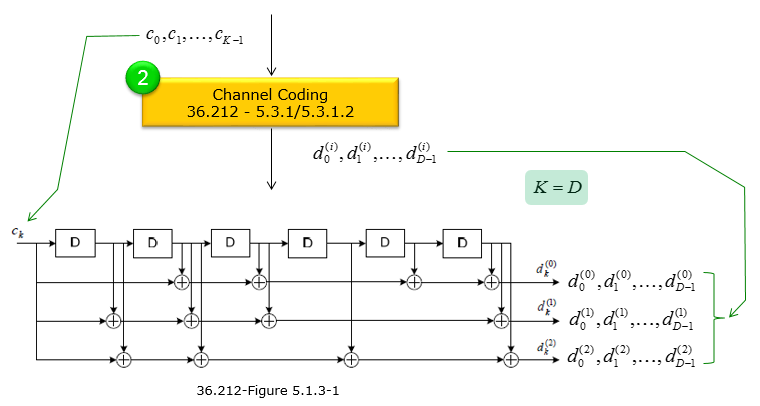
Channel Coding : 36.212-5.3.1Channel coding adds controlled redundancy to the transmitted data so that the receiver can detect and/or correct bit errors caused by noise, interference, and other impairments on the radio channel. In short, channel coding (e.g., convolutional coding, turbo coding, LDPC, etc.) improves the reliability and robustness of wireless communication links by allowing error correction mechanisms at the receiver. For BCH, a channel coding called 'Tail-Biting Convolutional' is used. Tail-biting convolutional coding ensures the encoder starts and ends in the same state without appending extra “tail” bits. In other words, the encoder effectively “wraps around” so that the last encoded bit transitions smoothly back to the initial state. This avoids the overhead of flushing the encoder registers, preserving throughput while still offering error correction capabilities. The overall channel coding process for BCH can be summarized as below. The size of array c[] is 24 (K = 24) and output of channel coding is 72 in total(each of three d[] array is 24 bits). The coding method is based on 36.212-5.1.3.1 Tail biting convolutional coding as brielfy illustrated below.
In this channel-coding procedure, the input bits c0, c1, …, cK−1 are passed through a tail-biting convolutional encoder in order to generate three separate output bit streams. Each output stream has the same length as the input (K), and so you get a total of 3×K coded bits. Below is a step-by-step outline of how the process works,.
If you really understand the details and try manually or with your own program. Please try following example.
c[] = { 0,0,0,0,0,0,0,0,0,0,0,0,0,1,0,0,0,0,0,0,0,0,0,0 } d1[] = { 0,0,0,0,0,0,0,0,0,0,0,0,0,1,0,1,1,0,1,1,0,0,0,0 } d2[] = { 0,0,0,0,0,0,0,0,0,0,0,0,0,1,1,1,1,0,0,1,0,0,0,0 } d3[] = { 0,0,0,0,0,0,0,0,0,0,0,0,0,1,1,1,0,1,0,1,0,0,0,0 } Rate Matching : 36.212-5.3.1Rate matching selects (or sometimes repeats and punctures) coded bits in a way that produces exactly the required number of bits for transmission (E). It adjusts the effective code rate to match the available resources and target data throughput without compromising error correction performance.
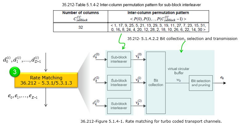
After the convolutional encoder produces three coded bit streams (d(0)k, d(1)k, d(2)k for k = 0..D−1), these streams are delivered to the rate matching block. Rate matching ensures that the total number of transmitted bits (E) matches the required code rate or available resource space (e.g., for PBCH). The bits d(i)0, …, d(i)D−1 (i = 0,1,2) are processed using the following main steps:
This entire “rate matching” process adjusts how many coded bits are ultimately transmitted, letting the system adapt to the available channel resources or target code rate. The final output ek (k = 0..E−1) goes on to modulation and physical-layer mapping. In summary, rate matching takes the three streams of tail-biting convolutionally coded bits and produces a final stream of size E. By doing so, it controls the effective coding rate for the PBCH or other physical channels.
:D is the number of bits in each of the three coded streams produced by the tail-biting convolutional encoder. Because it is “tail-biting,” no extra tail bits are added, so D = K (the input block size). For example, if K = 24 information bits go in, each of the three output streams has D = 24 bits, giving a total of 72 bits.
E is the number of bits after rate matching. It depends on how many bits must be transmitted for that channel (determined by the standard or by the physical resource allocation). The rate matching process (e.g., puncturing, repetition, or just “bit selection”) prunes or repeats coded bits so that the final output has exactly E bits. Figuring out E value is a challenge because it would vary depending on situation but for LTE PBCH case it is a fixed value since the number of physical resources (Resource Elements) and modulation scheme is fixed. Followings are further details, For the normal CP case in LTE, the PBCH is rate-matched to E = 240 bits per 10 ms radio frame. These 240 bits are then re-transmitted (or “repeated”) repeated over four consecutive radio frames (a 40 ms period), but each repetition still corresponds to the same 240-bit codeword. Why 240 Bits? Below is a simplified way to see where “240” comes from for normal CP and a single antenna port.
Hence, E = 240 is fixed by the PBCH’s resource mapping and overhead design for normal CP. For extended CP, it is slightly different (typically E = 224 bits).
A sub-block interleaver rearranges coded bits in two steps:
At the second step (i.e, reading out with a permutation) the Table 5.1.4-2 plays the crucial role. The bit sequence are first placed into a matrix having a certain number of columns (e.g., 32). Once the bits are loaded into this matrix row by row, the columns are read out in a permuted order according to the sequence provided in Table 5.1.4-2. Below is a brief overview of the meaning behind this table:
In other words, Table 5.1.4-2 defines the column “shuffling” pattern that the sub-block interleaver applies to improve the robustness and efficiency of the coding process.
Bit collection is essentially the final step of rate matching where the
circular buffer is read (with a possible offset k0)
until exactly E bits are gathered. Any In short This procedure ensures different redundancy versions pick different parts of the circular buffer for incremental redundancy or puncturing, thereby optimizing HARQ performance and code-rate flexibility. Following is overall procedure of the bit selection process.
Followings are breakdown of the bit selection process based on 36.212-5.1.4.1.2 In the LTE rate-matching procedure, bit collection describes how the convolutionally or turbo-coded bits (already interleaved) are placed into (and then read from) a circular buffer to form the final stream of E bits for transmission.
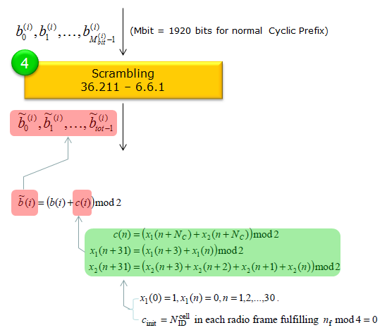
Scrambling : 36.211-6.6.1Scrambling randomizes the transmitted bits and helps mitigate interference from other cells using different scrambling codes. It also aids in reducing undesirable signal characteristics (like high peak-to-average power). Scrambling in LTE PBCH is essentially a bitwise XOR process that uses a cell-specific pseudorandom sequence. It randomizes the transmitted bits to help mitigate interference and reduce undesired signal characteristics such as high peak-to-average power. Each cell’s unique scrambling sequence is initialized using its cell ID, ensuring that overlapping cells do not interfere as severely. The output bit length remains the same, but each bit is toggled according to the scrambling pattern prior to modulation. This ensures that each cell’s PBCH has a unique scrambling pattern, improving cell-specific detection and overall system performance. Following is the overall procedure of the scrambling process
The image above shows how the PBCH bits are scrambled using a cell-specific sequence. This process applies to the Mbit bits of the PBCH: 1920 bits for normal cyclic prefix or 1728 bits for extended cyclic prefix. Following is the break down of the detailed process Before scrambling, you have a block of bits: b(0), b(1), …, b(Mbit – 1), where Mbit is either 1920 or 1728 depending on the cyclic prefix. These bits have already passed through the channel coding and rate matching steps.
The result of scrambling is a new sequence of bits ~b(0), ~b(1), …, ~b(Mbit – 1).. The number of bits remains the same as before ( 1920 or 1728). These scrambled bits then undergo modulation (e.g., QPSK) and are mapped onto the PBCH resource elements.
If you were following the process carefully, you may find some strange thing at this point. The output bit length of rate matching (the prior step) is 240 bits. Usually the output of a prior step(rate matching in this case) become the input of the next step (scrambling in this case). Why there is the discrepancies in terms of the bit length between the output of rate matching and the input of scrambling ? The short answer is that the specification counts the total bits over the four repeated PBCH transmissions (each 240-bit codeword is mapped and repeated) and accounts for 2 bits per resource element with QPSK. Although the rate matching step produces 240 bits for a single codeword, the next stage (scrambling) sees the entire four-transmission set (240 × 4 = 960) along with the 2 bits/RE detail, resulting in 1920 bits being scrambled in total. Followings are the detailed breakdown of the answer In each 10 ms radio frame, the PBCH occupies 4 OFDM symbols in subframe #0 (not four separate transmissions in that subframe). For normal CP and a single antenna port, there are 72 subcarriers × 4 symbols = 288 resource elements (REs) total for the PBCH region. After accounting for reference signals, you end up with 240 useful bits per subframe to carry the PBCH codeword. The same 240-bit PBCH codeword is transmitted again in subframe #0 of the next 3 frames. That’s a total of 4 identical transmissions in frames #0, #1, #2, and #3 (spanning 40 ms). This repetition (one per 10 ms frame) is what gives a UE multiple chances to decode the broadcast information. After rate matching, you have a 240-bit codeword for a single PBCH transmission in one subframe. However, from the perspective of the scrambler and QPSK modulation across a full 40 ms repetition period, standards often talk about Mbit = 1920 bits. That comes from 240 bits × 2 (QPSK) × 4 transmissions, or from the view that you have 960 REs × 2 bits each. The exact wording in the spec can sometimes make it seem like 1920 bits are used “at once,” but it’s effectively counting the total bits that appear over the four repeated transmissions.
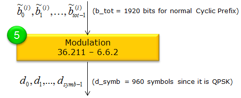
Modulation : 36.211-6.6.2After the PBCH bits have been scrambled, the resulting sequence ~b(0), ~b(1), …, ~b(Mbit−1) is mapped to complex-valued symbols using QPSK, as specified in the specification.
In QPSK, every pair of bits forms one modulation symbol. That means if Mbit is the total number of scrambled bits, the number of symbols, Msymb, becomes Mbit / 2. For the PBCH, QPSK is always used. Hence:
Each complex QPSK symbol (e.g., d(0), d(1), …, d(Msymb−1)) is placed onto the PBCH resource elements in subframe 0 for transmission over the air. This final modulation step transforms the scrambled bits into waveforms suitable for the physical downlink channel. Resource Element Mapping : 36.211-6.6.4Resource element mapping refers to the process of placing the modulated symbols onto specific subcarrier and OFDM symbol positions in the LTE time-frequency grid. It ensures each bit of data is transmitted in a known, standardized location, taking into account the resource elements reserved for reference signals or other overhead. By defining a clear mapping sequence, the system guarantees that both the transmitter and receiver align on where data and control information should be sent and received
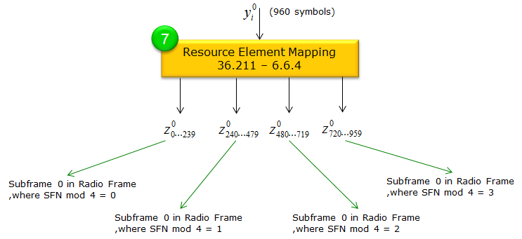
After QPSK modulation, we have Msymb complex symbols {y(p)(0), …, y(p)(Msymb−1)} for antenna port p. In the normal CP case, Msymb = 960 (i.e., 240 bits × 2 bits/symbol × 4 transmissions). These symbols are transmitted during 4 consecutive radio frames, starting in the frame where nf mod 4 = 0, and continuing through frames where nf mod 4 = 1, 2, and 3. Each set of 240 bits produces 960 QPSK symbols for normal CP. The same PBCH codeword is effectively reused in subframe 0 of the next three frames, providing four total transmissions over 40 ms. The 960 symbols y(p)(i) are mapped into resource elements (REs) in subframe 0 according to the following rules:
The identical 240-bit PBCH codeword is transmitted in subframe 0 for four consecutive frames:
This repetition ensures the UE can reliably decode the PBCH even if it starts listening mid-way through the 40 ms cycle.
Repetition for Robustness: Multiple transmissions of
the same codeword across four frames improve the chances of successful
decoding. PBCH Resource Element Allocation with different Antenna ConfigurationFollowings are an example of PBCH Resource Element mapping for each of Antenna of 1 Antenna Configuration. (eNB physical cell ID is set to be 0 and System Bandwidth is set to be 20 Mhz).
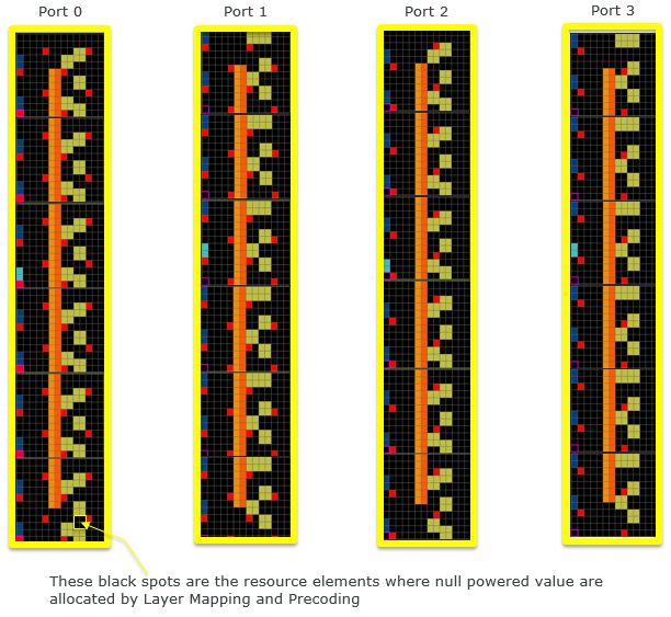
Followings are an example of PBCH Resource Element mapping for each of Antenna of 4 Antenna Configuration. (eNB physical cell ID is set to be 0 and System Bandwidth is set to be 20 Mhz). At a glance, you would notice a little bit different patters of resource allocation at each antenna. At first, I thought there might be different RE mapping rule for each antenna. However, I don't find any of those differences in 36.211 6.6.4 and then I learned that these different pattern comes from the allocation of null symbol (zero powered symbol) inserted during layer mapping and precoding process.
How to specify Antenna configuration in PBCHPBCH carry the information about the antenna configuration (the number of Antenna ports being used for a cell). But if you look at the MIB message itself you wouldn't see any information elements about the number of antenna ports. Then how the PBCH can carry the antenna configuration in it ? It is done by using special CRC mask (the number of bit stream being masked(XORed) over the CRC bits. Number of CRC bits for PBCH is 16 bits, so the length of the CRC mask is 16 bit as well. Following tables shows the types of CRC mask representing each of the antenna configurations. < 36.212 Table 5.3.1.1-1 : CRC mask for PBCH >
PBCH Eoncoding in srsRANIf you are interested in this process at the source code level of the protocol stack, I would suggest you to look into the openSource srsRAN. Following APIs can be good places for you to start. This list is from the master-branch of the code that was downloaded on Oct 8,2021
PBCH Decoding in srsRANIf you are interested in this process at the source code level of the protocol stack, I would suggest you to look into the openSource srsRAN. Following APIs can be good places for you to start. This list is from the master-branch of the code that was downloaded on Oct 8,2021
|
||
