In order to get a repeatble, reliable and stable measurement result, it is very important to place the AUT(Antenna Under Test) and the measurement antenna in proper position. In this page, I will explain on how to determine the proper antenna position and theoretical background on why the specific posiiton should be used.
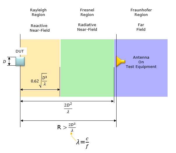
Minimum far-field distance R for a traditional far field anechoic chamber are determined by the formula a shown below (Based on R5-180013).
The near/far field boundary for different antenna sizes and frequencies is shown in the table below. This table is based on R5-180013 (Ref [1]) - Table 2.2.1: Near field/far field boundary for different frequencies and antenna sizes for a traditional far field anechoic chamber
|
D(cm) |
Freq(Ghz) |
|
Near/Far Boundary (cm) |
Path Loss |
|
5 |
28 |
47 |
48 |
55 |
|
10 |
28 |
187 |
188 |
66.9 |
|
15 |
28 |
420 |
420 |
73.8 |
|
20 |
28 |
747 |
748 |
78.9 |
|
25 |
28 |
1167 |
1168 |
82.7 |
|
30 |
28 |
1680 |
1680 |
85.9 |
|
5 |
100 |
167 |
168 |
76.9 |
|
10 |
100 |
667 |
668 |
88.9 |
|
15 |
100 |
1500 |
1500 |
96 |
|
20 |
100 |
2667 |
2668 |
101 |
|
25 |
100 |
4167 |
4168 |
104.8 |
|
30 |
100 |
6000 |
6000 |
108 |
As shown below, the span of Radiative Near Field (the gap between the end of Reactive Near Field and the Start of Far Field) gets drastically increases as frequency increases where as Reactive Near Field distance relatively slowly increases). Also, comparing the following two plots, you would notice that the Far Field distance gets drastically larger as D increases.

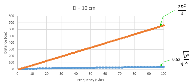
Now you may have an interesting question. According to the plots shown above, the distance between DUT antenna and equipment antenna should increase as frequency increases. That is, the size of Anechoic chamber should increases as frequency increases ? Isn't it counter intuitive to you ? Our common sense (our RF intuition) says the size of frequency dependent object tend to decrease as frequency increases.
How do we handle this conflict with our intuition and the plots show above ?
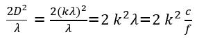
The solution lies in the fact that D is not a constant in realilty. In case of plots shown above, D has a fixed value regardless of frequency. But when we design an antenna, we usually decide D value(Antenna Aperture size) in terms wavelenth as shown below. Here, k is just a constant like 0.5, 1, 2 etc.
![]()
If you plot on how wavelength (lamda) changes as frequency increases, you will get a plot as shown below. You will notice that the wavelength decrease dtrastically.
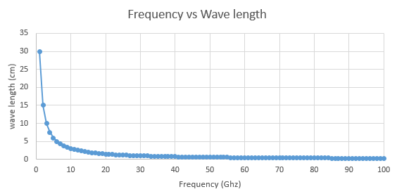
If you rewrite Far Field distance equation, it becomes as shown below. In this equation, you will notice that the Far Field distance decreases as frequency increases. (NOTE : if you want to try calculate in real value, take f as 'frequency in Hz' and c as 'the speed of light in m', k is just a constant without any unit).
Why testing in Far Field ?
Probably by now, you may have a question 'Why do we need to test in Far Field ?'. It would not be easy to get a direct answer to this question. So let me change the question a little bit. Why we do not test in Near field ?
The simple answer to this question is that the measurement result in this region tend to be unpredictable and subject to change with small changes in the environment surrounding the antenna(e.g, electrical circuit feeding the antenna) and location changes. On the contrary, the field pattern in Far field is more stable and predictable and less senstive to small surrounding components.
For those who are interested in further details, let's look a little bit further details on the characteristics in each of the region. You may investigate even further on your own. Try googling the keywords like 'Near and Far Field', 'Field Region around Antenna' etc.
Reactive Near Filed : This is the area that is very close to the antenna. The relationship between E and H field in this region is very unpredictable (It is unpredictable not because this property goes against a physical theory, but because the physical property is so complicated). For example, at one point you would see E field dominates and at another point right besides the previous point H field dominates. Also radiated energy would influence back and forth with surrounding electrical component like antenna control circuit. For example, some portions of radiated energy gets absorbed and stored in surrounding component at some point of time and the stored energy gets radiated back into the space at other point of time and influence radiation pattern.
Radiative near field (Fresnel region) : In this region, the distance from the antenna is not so close to be influenced by reative electrical components as described above and the E and H field relationship is much more predictable comparing to Reactive Near Field. However, the E and H field relationship is still pretty complex and there are high possibilities where some physical object that may affect the radiation pattern in this area. For example, some metal object like steel beam holding up the antenna module can act as a kind of antenna or reflector. So this kind of object can influence on the radiation pattern of the AUT(Antenna Under Test).
Reference
[1] 3GPP TSG-RAN WG5 Adhoc Meeting#1 - R5-180013 : Signalling NR Testcases - OTA chamber requirements
[2] Near and far field (Wikipedia)