EIRP stands for Effective Isotropic Radiated Power or Equivalent Isotropic Radiated Power. I think this will be a keyword (but somewhat confusing word) for a while at the early stage of 5G/NR RF/mmWave Measurement.
- A Few Related Keywords
- 3D to 2D Presentation
- Nomenclatures for Beam Characteristics
- Fundamental Definition of EIRP
- EIRP in Practice
A Few Related Keywords
Even though the concept EIRP may apply to any type of radiation pattern, the case where this term gets special importance is Antenna or Antenna array which has highly directional radiation pattern. This kind of highly directional radiation pattern is called as a Beam. Before I proceed to the description of EIRP, I want to introduce several keywords that would often be used under the context of EIRP. These keywords and definitions are mainly from Ref [1]. As you may notice, the definition here would seem to be very dry and not easy to grasp the real meaning. I will try to describe in more practical sense or visualize if possible later in this page... but it will take some time. Keep revisting this page :)
In addition to these words, it will be helpful if you read through Antenna Performance page if you are not familiar with antenna related terminologies.
|
Terms |
Definition |
|
Beam |
The main lobe of the radiation pattern of an antenna array |
|
Beam centre direction |
Direction equal to the geometric centre of the half-power contour of the beam |
|
Beam direction pair |
Data set consisting of the beam centre direction and the related beam peak direction |
|
Beam peak direction |
Direction where the maximum EIRP is found |
|
Beamwidth |
Beam which has a half-power contour that is essentially elliptical, the half-power beamwidths in the two pattern cuts that respectively contain the major and minor axis of the ellipse |
|
EIRP accuracy directions set |
Beam peak directions for which the EIRP accuracy requirement is intended to be met |
|
Equivalent Isotropic Sensitivity |
Power level relative to an isotropic antenna that is required to be incident on the AAS BS array from a specified azimuth/elevation direction in order to meet a specified receiver sensitivity requirement |
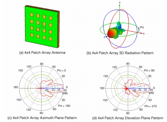
3D to 2D Presentation
In reality, the signal radiate into 3 Dimensional Direction as illustrated (b) in the following figure. However, it is not always easy to represent the propagation patterns in 3D and sometimes it is even harder to estimate the energy propagation quantatively when it is plotted in 3D. So in many case, we cut through the 3D pattern along a specific 2D plane as shown in (c) and (d). This plot came from Ref [3]. At first, you would need some practice to correlate the 3G propagation pattern to 2D cut-through pattern. If you are really good at the correlation, you would be able to reconstruct the rough image of 3D pattern out of 2D cut-through patterns. In Ref [3], you would find some more examples of radiation pattern and you can do this 3D <--> 2D conversion practice.
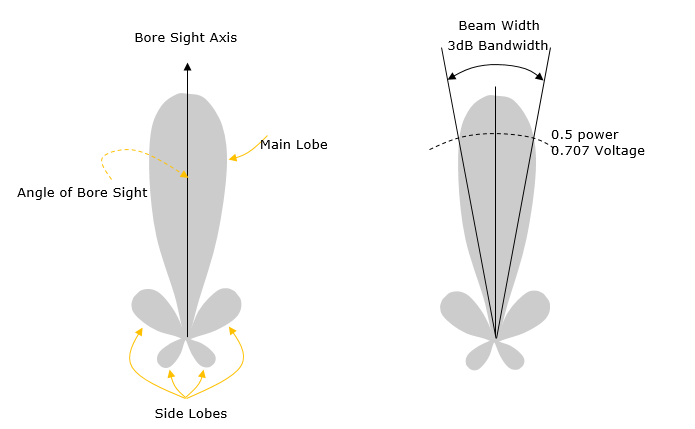
Nomenclatures for Beam Characteristics
Following illustration shows two diagrams illustrating the nomenclatures for beam characteristics. This is to get you familiar with basic terminologies which are frequently used to describe on antenna radiation pattern.
Fundamental Definition of EIRP
First let me start with a formal definiton from 3GPP document (Ref [1]). It is described as below :
Equivalent Isotropic Radiated Power: in a given direction, the relative antenna gain of a transmitting antenna with respect to the antenna gain of an isotropic radiating element multiplied by the net power accepted by the antenna from the connected transmitter
NOTE: For an AAS BS the EIRP can be seen as the equivalent power radiated from an isotropic radiating element, producing the same field intensity as the field intensity radiated in the declared beam pointing direction of the active antenna system being considered.
Now I would try to decribe the same thing in more practical and intuitive way, I hope this would give you somewhat easier understanding.
As you see the descriptions above, most of the antenna performance parameters like Gain / TIP / TIS are based on the measurement across the whole surface and some additional processing afterwards, but EIRP is a measurment showing a performance at a specific point only (i.e, the measurement at a specific angle (Phi, Theta).
EIRP = Tx RF Power(dBm) + G(dB) - L(dB)
Tx RF Power :RF power measured at RF connector of the unit
G :Antenna gain
L : Feeder loss(cable loss or any other loss)
EIRP in Practice
In engineering, there is almost nothing you can completely understand without doing on your own. There might be some smart-mind who can grasp the complete understanding based on written description only, but at least I am not such a smart-mind. When I am learning a new thing, I am always to try to find any chance for me to try myself or to find anybody who has real experience. Of course, it is not always successful. Sometimes I am lucky enough to find the people who can help me right away, but sometimes it takes several years.. sometimes never, no luck. Fortunately I was lucky at this time and had an old friend who has both theoretical understandings and hands-on experience as well. This section is based on a lot of back-and-forth with YongSung Choi who gave me a lot of practical insight on this.
I will describe on the definition of EIRP in terms of how it is measured in real practice. Let's assume that a DUT is at the center of a Spherical coordinate as shown below and the measurement antenna is a point on the surface of the sphere. We use two angular parameter theta and phi to represent a location on the surface of the coordinate.
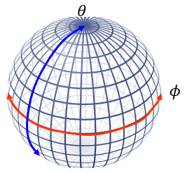
Now let's assume that we measure the Transmission power from the DUT at every grid point shown above (Theoretically to do this, you need to move the location of measurement antenna across all the grid point on the spherical surface, but in many case we rotate the DUT in Phi and Theta angle with the measurement antenna remain fixed).
Now you can create a big table as shown below filling each cell with the measured power at each grid points (i.e, at each Phi and Theta value).
|
|
Phi |
||||||
|
Theta |
0 |
... |
80 |
... |
... |
... |
360 |
|
... |
21 |
22 |
19 |
... |
... |
... |
|
|
90 |
20 |
25 |
18 |
... |
... |
... |
|
|
... |
22 |
23 |
20 |
... |
... |
... |
|
|
180 |
... |
... |
... |
... |
... |
... |
|
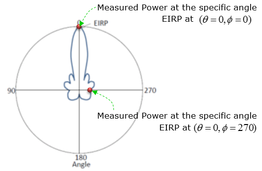
Then, let's think of how we can get EIRP from this table. But the EIRP value that you have to get from this table would vary a little bit depending on the context. Depending on how you are asked, the value at each and every cell in the table can be an EIRP, OR the single maximum value in the whole table can be the EIRP of the DUT.
- If you are asked to give the EIRP at a specific angle (e.g, if somebody ask you 'what is the ERIP at Phi = 10, Theta = 90 ?), you would give the value in the cell representing the specified angle.
- If you are asked to give the EIRP without any further requirement (e.g, if somebody ask you 'what is the EIRP of the DUT ?'), you would give the maximum value within the whole table.
- If somebody ask you 'what is the beam direction or beam center of the DUT ?', you would give them the Phy and Theta value that holds the maximum EIRP value in the table.
Reference
[1] 3GPP TR 38.817-02 V0.5.0 (2017-12) - NR;General aspects for BS RF for NR(Release 15)
[2] PCB-Embedded Antenna for 80 GHz Chip-to-Chip Communication
by Jae-Young Chung, Wonbin Hong, Kwang-hyun Baek, Young-ju Lee
JOURNAL OF ELECTROMAGNETIC ENGINEERING AND SCIENCE, VOL. 14, NO. 1, 43 45, MAR. 2014
[3] Some Common Antenna Radiation Patterns
[4] 3GPP TR 37.842 V13.2.0 (2017-03) - Radio Frequency (RF) requirement background for Active Antenna System (AAS) Base Station (BS)(Release 13)