The functionality of BSR in NR is exactly sa the LTE BSR. For the BSR functionality, refer to LTE BSR page. The dfference is the structure of MAC CE and the length of Buffer Size Bit field. It is understandable that the length of the BSR bit field in NR would be longer than LTE BSR. Another difference is that NR BSR has explcit bit field for LCG as shown below whereas LTE BSR specifies LCG implcitely.
Simply put, Buffer Status Report (BSR) is a message from UE to eNB (MAC layer command) saying 'I have this amount of data to send would you give grants big enough to transmit all of these data ?"
As a formal definition, 38.321-5.4.5 states as follows :
Followings are the topics to be convered in this note.
- Parameters for BSR and Overall Operation
- Data Structure of BSR MAC CE
- Selection of BSR Type
- RRC Parameters for BSR
Parameters for BSR and Overall Operation
In order to send BSR, the first thing UE has to do is to estimate how much data it has to transmit. This process is called 'Data Volumn Calculation'. The data volumn to transmit is based on how much data is in RLC and PDCP. Regarding RLC layer data volumn calculation, there are several factors to be used to calculate the data volumn as listed below (based on 38.322-5.5)
- RLC SDUs and RLC SDU segments that have not yet been included in an RLC data PDU;
- RLC data PDUs that are pending for initial transmission;
- RLC data PDUs that are pending for retransmission (RLC AM).
Regarding PDCP layer data volumn calculation, there are also factors to be used to calculate the data volumn as listed below (based on 38.322-5.5)
- the PDCP SDUs for which no PDCP Data PDUs have been constructed;
- the PDCP Data PDUs that have not been submitted to lower layers;
- the PDCP Control PDUs;
- for AM DRBs, the PDCP SDUs to be retransmitted according to 38.322-5.1.2;
- for AM DRBs, the PDCP Data PDUs to be retransmitted according to 38.322-5.5.
Once Data Volumn Calculation is done, UE need to determine exactly when it needs to send BSR and for which logical channel it wants to send. There are multiple parameters affecting this decision making. According to 38.321-5.4.5, those parameters are as follows :
- periodicBSR-Timer;
- retxBSR-Timer;
- logicalChannelSR-DelayTimerApplied;
- logicalChannelSR-DelayTimer;
- logicalChannelSR-Mask;
- logicalChannelGroup.
These parameters can be configured by Rrc message.
Data Structure of BSR MAC CE
Short BSR is a format for a Short Buffer Status Report (BSR). These reports are used to inform the network about the status of data buffers in the User Equipment (UE). The following diagram outlines the structure of these reports, which include fields for the Logical Channel Group ID (LCG ID) and Buffer Size.
The LCG ID is used to identify which group of logical channels the report pertains to, and the Buffer Size field indicates the amount of data waiting to be transmitted.
< 38.321-Figure 6.1.3.1-1: Short BSR and Short Truncated BSR MAC CE >

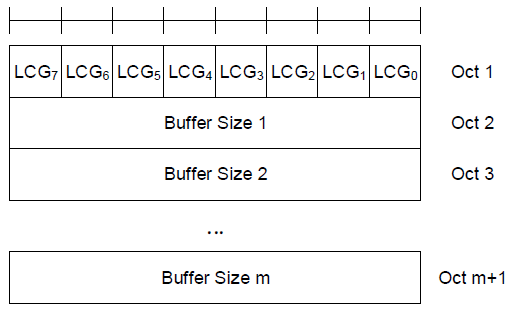
Folliwng diagram displays a format for a Long Buffer Status Report (BSR) and Long Truncated BSR in the context of MAC in a cellular communication system. This extended version of the BSR includes multiple Logical Channel Group IDs (LCG0 to LCG7), each corresponding to a different group of logical channels. For each LCG ID, there is a corresponding Buffer Size field (Buffer Size 1 to Buffer Size m) that indicates the volume of data queued for each logical channel group.
< 38.321-Figure 6.1.3.1-2: Long BSR and Long Truncated BSR MAC CE >
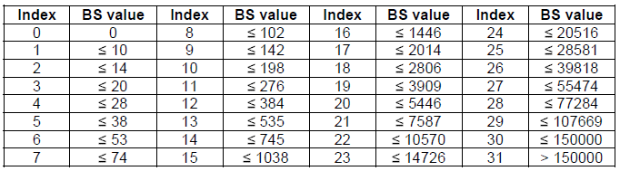
Following table shows a table listing buffer size levels for a 5-bit Buffer Size field in bytes, which is used for the short BSR. Each entry in the table corresponds to an index value that can be sent in the Buffer Status Report (BSR) from a UE to inform the network of the amount of data that is buffered and ready to be transmitted.
The table is divided into 32 index values (from 0 to 31), as 5 bits can represent 32 different states. Each index has a corresponding Buffer Size (BS) value, which is the maximum number of bytes that the UE's buffer can hold for that index value. For example, an index of 0 corresponds to a BS value of 0 bytes, indicating an empty buffer, while an index of 31 indicates a BS value greater than 150,000 bytes, which corresponds to the largest buffer size represented in this table.
The buffer size values increase non-linearly, with smaller increments at lower index values and larger increments at higher index values. This allows for finer granularity in reporting small amounts of data and coarser granularity for larger volumes, optimizing the reporting process for different traffic conditions and data requirements.
< 38.321-Table 6.1.3.1-1: Buffer size levels (in bytes) for 5-bit Buffer Size field >
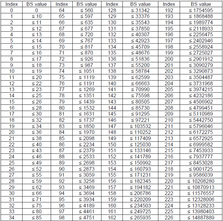
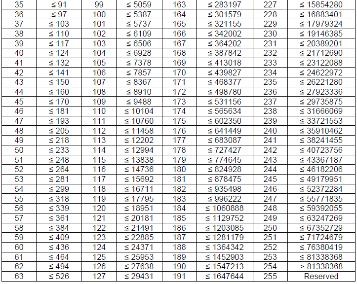
Following table shows buffer size levels for an 8-bit Buffer Size field in bytes which is used in long BSR MAC CE. With 8 bits, there are 256 possible index values (0 to 255), and each index corresponds to a Buffer Size (BS) value. This table serves a similar purpose to the 5-bit table shown above but allows for much finer granularity in reporting the size of the UE's data buffer to the network. The BS values range from 0 bytes to well over 8 million bytes, increasing non-linearly with the index. The larger the index value, the larger the range of data that can be represented, which reflects a more precise buffer status as the buffer size increases.
< 38.321-Table 6.1.3.1-2: Buffer size levels (in bytes) for 8-bit Buffer Size field >
Selection of BSR Type
From the UE side, what type of BSR it should use when it is supposed to send a BSR ? It is described in 38.321-5.4.5. It is pretty long (confusing to me) statement. It would be summarized as follows (I hope I didn't get mixed up).
|
Type of BSR |
Conditions for Sending |
|---|---|
|
Short BSR |
- Only one LCG has data available for transmission when the MAC PDU is to be built. |
|
Padding BSR |
- UL resources are allocated, and the number of padding bits is equal to or larger than the size of the BSR MAC CE plus its subheader, but not enough to send a Long BSR. |
|
Long BSR |
- More than one LCG has data available for transmission when the MAC PDU containing the BSR is to be built. |
RRC Parameters for BSR
MAC-CellGroupConfig ::= SEQUENCE {
drx-Config SetupRelease { DRX-Config } OPTIONAL, -- Need M
schedulingRequestConfig SchedulingRequestConfig OPTIONAL, -- Need M
bsr-Config BSR-Config OPTIONAL, -- Need M
tag-Config TAG-Config OPTIONAL, -- Need M
phr-Config SetupRelease { PHR-Config } OPTIONAL, -- Need M
skipUplinkTxDynamic BOOLEAN,
...,
[[
csi-Mask-v1530 BOOLEAN OPTIONAL , -- Need M
dataInactivityTimer-v1530 SetupRelease { DataInactivityTimer } OPTIONAL -- Need
PCellOnly
]]
}
BSR-Config ::= SEQUENCE {
periodicBSR-Timer ENUMERATED { sf1, sf5, sf10, sf16, sf20, sf32, sf40, sf64,
sf80, sf128, sf160, sf320, sf640, sf1280,
sf2560, infinity },
retxBSR-Timer ENUMERATED { sf10, sf20, sf40, sf80, sf160, sf320, sf640,
sf1280, sf2560,sf5120, sf10240, spare5, spare4,
spare3, spare2, spare1},
logicalChannelSR-DelayTimer ENUMERATED { sf20, sf40, sf64, sf128, sf512, sf1024,
sf2560, spare1} OPTIONAL, -- Need R
...
}
Reference
[1]