N6 is the reference point between the UPF and a Data Network. 23.501 defines it in a single line, and that line really is the whole of it. But N6 behaves unlike every other reference point drawn on the same architecture figure, and the reason is worth understanding before anything else.
Look at its neighbours. N2 joins the gNB and the AMF. N3 joins the gNB and the UPF. N4 joins the SMF and the UPF. Both ends of each of those are 3GPP functions, so 3GPP can specify the protocol that runs between them. N6 is not like that. One end is the UPF, and the other end is a Data Network. 3GPP does not own the Data Network, so it cannot specify what runs there.
The consequence is direct. There is no N6 protocol, no N6 message set, and nothing in a capture that decodes as N6. What you see on the wire is an ordinary IP packet, an Ethernet frame, or a UDP tunnel, depending on the PDU Session type. To the Data Network, the UPF simply looks like a router.
That absence is exactly why N6 deserves a page of its own. Almost everything an operator adds beyond plain connectivity sits on N6 : the NAT, the firewall, the DNS resolver, the CDN, the edge application server. N6 is also where a UE can get its IP address from. It is where a DN-AAA server can refuse a PDU Session outright. And it is where a link MTU set one octet too high starts fragmenting traffic. None of that is visible from the 3GPP side of the UPF.
Let's work through it in order. First what N6 is and where it sits, then why it has no protocol, then what it looks like for each PDU Session type. After that we can take the parts that cause real trouble in the field. Those are address allocation, more than one N6 on a single session, and the MTU. The last section then asks how much of all that a given implementation actually has to do.
- Executive Summary
- What is the N6 interface ?
- Why does N6 have no protocol of its own ?
- N6 and SGi : what actually changed from 4G ?
- What does N6 look like for each PDU Session type ?
- Who gives the UE its address, and what does N6 carry for it ?
- Can one PDU Session have more than one N6 ?
- N6, N9 and N19 : which one carries what ?
- What does an operator actually put on N6 ?
- Why link MTU turns into an N6 problem
- Which signalling messages actually touch N6 ?
- How much of N6 does an implementation actually have to do ?
- Reference
Executive Summary
The table below is a lookup, not an argument. Each row names one area, and the sections further down carry the reasoning behind it.
Area |
Main Topics |
Summary |
Implication |
23.501-4.2.7, UPF as PDU Session Anchor |
N6 joins the UPF acting as PSA to a Data Network. An intermediate UPF has no N6 at all. |
If you are looking for N6, look at the anchor rather than at the first UPF in the path. |
|
29.561-8.2.1, GTP-U termination |
3GPP standardises nothing on N6. The UPF appears to the DN as a normal IP router, and L2 and L1 are operator specific. |
Nothing in an N6 capture identifies the traffic as 5G. The QFI does not survive past the anchor. |
|
23.501-5.6.10, 29.561-8, 29.561-9, 29.561-14 |
IP gives a routed interface, Ethernet gives a bridged one, and Unstructured gives a point to point tunnel over UDP/IPv6. |
The PDU Session type decides what the far end of N6 has to be configured as. |
|
23.501-5.6.6, 29.561-10, 29.561-11, 29.561-12 |
DHCP, RADIUS and Diameter towards the DN can allocate the address and authorize the session. The SMF may reach the DN-AAA server directly instead of through the UPF. |
A PDU Session can fail for a reason that lives entirely outside the operator's core. |
|
23.501-5.6.4.2, 23.501-5.6.4.3 |
An UL CL or a Branching Point puts a second PSA on the path, so one PDU Session ends up with two N6 interfaces. |
Edge computing depends on this. The UE is never told, and keeps the single address it already has. |
|
N6-LAN, 23.501-5.8.2.23, 29.561-13, 29.561-15, 29.561-18, 29.561-22 |
NAT, firewall and DPI on N6 are operator choices. 3GPP has since added specific N6 features such as delay measurement, PIM, L2TP and proxying for encrypted media. |
The boundary is moving. Treating N6 as entirely outside 3GPP is no longer accurate. |
|
23.501-5.6.10.4, 23.501 Annex J |
Tunnel and IPsec overhead reaches 142 octets, so a transport MTU of 1500 leaves a link MTU of 1358. |
Traffic fragments when a UE ignores the advertised MTU, and the backbone and N6 carry the cost. |
|
29.244 PFCP, 24.501 NAS, 38.413 NGAP |
N4 configures N6. NAS carries the DNN going in and the address, the ePCO and cause #29 coming back. NGAP has one IE, N6 Jitter Information. |
A protocol trace tells you which N6 was chosen and what it returned, but almost nothing about how it was built. |
|
Not a 3GPP concept. Optional features from 23.501 and 29.561 |
N6 support ranges from GTP-U termination on its own, up to a UPF that bridges Ethernet, inserts local anchors and proxies encrypted media. |
Ask which features a product has. A datasheet line saying N6 is supported carries almost no information. |
What is the N6 interface ?
Let's start with where N6 sits, because its position explains most of its behaviour. N6 is the last segment of the user plane. It carries the UE's traffic after the 5G system has finished with it, and before the service the UE actually wanted.
23.501-4.2.7 lists it in one line, next to N1, N2, N3, N4 and N9 :
Which Data Network you reach is decided by the DNN the UE asked for. One DNN might lead to the public internet. Another might lead to an IMS network, to an enterprise LAN, or to an edge site running an application server a few kilometres from the cell. All of them are Data Networks, and every one of them meets the 5G system over N6.
23.501 Figure 4.2.3-2 draws the non-roaming architecture in reference point representation, and the copy below marks N6 on it. Each reference point is a numbered oval on the line joining two functions. The oval for N6 is coloured red, and its line is the only one in the whole drawing that leaves the 5G system.
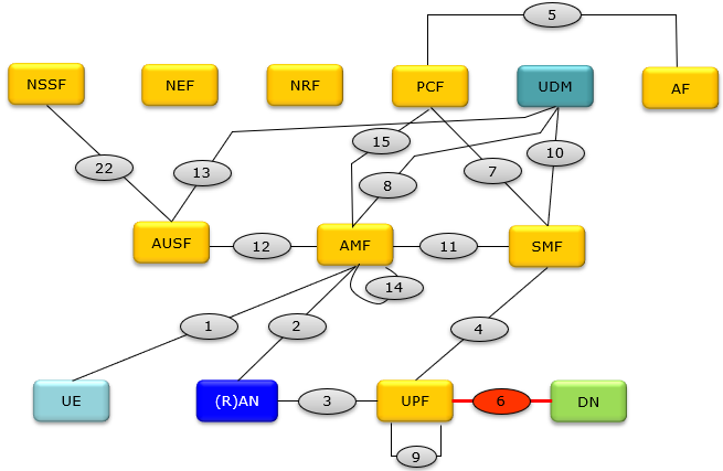
The red oval marks the edge of what 3GPP specifies. Everything to the left of it is defined by 3GPP. Everything to the right of it belongs to whoever runs the Data Network, and that is usually a different team, often a different company.
The DN box is the only one with nothing inside it : every other box in 23.501 Figure 4.2.3-2 is a named network function, with specified behaviour and specified services. The DN is drawn as a plain box because 3GPP describes nothing within it.N6 sits on the bottom row, with N3 and N9 : that row is the user plane. Oval 3 joins the (R)AN to the UPF. Oval 9 loops back on the UPF for UPF to UPF traffic, and oval 6 carries on to the DN.No control plane reference point crosses to the DN : the SMF reaches the UPF over N4, drawn as oval 4. Keep that in mind, because the DN-AAA signalling discussed later has to cross the same boundary somehow.
Why does N6 have no protocol of its own ?
This is the question that makes N6 confusing the first time you meet it. You can name the protocol on every other user plane reference point. N3 and N9 carry GTP-U, and N4 carries PFCP. Ask what N6 carries and the honest answer is that it depends, and that 3GPP chose not to decide.
29.561 is the stage 3 document for this boundary, and clause 8.2.1 states the position plainly :
So the design goal is that N6 should look ordinary. A router on the DN side should not need to know that a 5G network sits behind it. That is what lets an operator connect a 5GC to peering, to an enterprise site, or to an internet exchange. The equipment there needs no 3GPP awareness at all.
To see what actually happens to a packet, follow one across the user plane. Figure 1 stacks the protocols on each hop, from the UE through the (R)AN and the UPF to the Data Network.
Figure 1. The tunnel is what makes the first two hops 3GPP business, and the tunnel stops at the anchor. Once the UPF strips GTP-U, the wire carries the packet the UE built, so N6 needs no protocol of its own.
Follow an uplink packet through Figure 1 and the point becomes concrete. The UE builds an IP packet and hands it to SDAP. It reaches the (R)AN over Uu, and the (R)AN puts it inside a GTP-U tunnel towards the UPF. The UPF acting as PSA removes the GTP-U, UDP and IP headers that the tunnel added, then forwards what is left. What is left is the packet the UE built. Nothing was added to it along the way.
One consequence surprises people during QoS troubleshooting. The QFI travels in the GTP-U header, so it dies at the anchor. A QoS Flow is a concept that exists between the UE and the UPF, and no further. In the downlink direction the UPF has to rebuild that information. It matches arriving N6 packets against the Packet Detection Rules the SMF installed over N4.
N6 is a boundary, not a protocol : it names where the 5G system stops. Asking which protocol N6 uses is asking the wrong question.The UPF is a router to everything on the far side : 29.561-8.2.1 makes that explicit. It is why ordinary routing equipment can sit on N6 with no 5G awareness.QoS information does not cross N6 : the QFI is carried in GTP-U and is gone once the anchor strips it. Downlink QoS is reconstructed by the UPF from PDRs, rather than read off the packet.Transport level marking is the one exception : under 29.561-8.3 the operator may set the DiffServ Code Point from the 5QI and Priority Level. A DSCP value is therefore the only 5G derived hint an N6 packet can carry.
N6 on a software UPF : TUN, TAP and a routing table
Everything above says what N6 is not. Let's make it concrete with the implementation most people can run on a laptop. If you have ever started open5gs or free5GC, you have already built an N6 interface, and it was very likely a Linux TUN device.
Recall that 29.561-8.2.1 leaves L2 and L1 on N6 to the operator. A TUN device is a perfectly valid answer to that. It is a virtual interface that hands IP packets to a userspace program instead of to a wire. The UPF opens it, and every packet written there is a packet that has left the 5G system.
Trace an uplink packet through it. The UPF receives GTP-U on its N3 socket and strips the outer IP, UDP and GTP-U headers. It then writes what is left to the TUN file descriptor. The kernel treats that packet as though it had arrived on an ordinary interface, consults the routing table, and forwards it. In open5gs the device is called
Now the part to be careful about.
With that settled, the mapping is tighter than it first looks.
What this page calls it |
What it is on Linux |
The GTP-U socket decapsulating, then a write to the TUN file descriptor. |
|
A |
|
A |
|
No interface at all. A UDP socket aimed at one pre-configured application server. |
|
One TUN device per DNN, or a VRF, or a network namespace. |
|
Literally true here. The Linux host is the router, and it has no idea the traffic came from a 5G network. |
The TUN and TAP split lining up with the IP and Ethernet PDU Session types is not a coincidence. Both are the same choice between layer 3 and layer 2. That is also why a TUN device cannot model an Ethernet PDU Session. It carries no MAC address, so there is no ARP to answer and nothing to learn.
Two limits are worth stating, so the comparison is not taken too far. A TUN device is a lab and software realisation, and it is not what N6 usually is. A commercial UPF terminates N6 on a physical port, a VLAN sub-interface or a VRF. A UPF built on DPDK, VPP or XDP has no TUN anywhere, because it bypasses the kernel entirely, and its N6 side is a poll mode driver port instead.
One last placement. A TUN based UPF sitting behind iptables lands near the bottom of the ladder in the implementation levels section. It strips and adds GTP-U and it routes a UE pool, which is most of what the first two rungs ask for. Nothing on its N6 authorizes a session or steers traffic anywhere.
A TUN device is the N6 interface, not the DN : it is the port packets leave through, and the Data Network is the routing domain they enter next.TUN and TAP map onto the IP and Ethernet session types : both are the same layer 3 against layer 2 choice. A TUN device therefore cannot carry an Ethernet PDU Session.A lab UPF is the proof of the L2 and L1 rule : 29.561 declined to specify those layers. A virtual kernel interface is therefore as valid an N6 as a 100G port.Do not generalise from the laptop : a production UPF terminates N6 on a physical port or a VRF, and a kernel bypass UPF has no TUN device at all.
N6 and SGi : what actually changed from 4G ?
If you worked on EPC, you have met this interface already under a different name. SGi is the reference point between the PGW and the PDN, and N6 occupies exactly the same place in the picture. The similarity is deliberate, and it is worth being precise about what was kept and what was not.
The strongest evidence for continuity is the specification itself. 29.561 is the 5G document for interworking with external Data Networks. It inherits its structure, its DHCP handling and its RADIUS and Diameter attribute lists from 29.061. That earlier document did the same job for GPRS and EPS. Move a service platform from SGi to N6, and you usually keep the same AAA server, the same address pools and the same attribute set.
In EPS |
In 5GS |
What the change means |
Same position, same absence of a 3GPP protocol. A router facing the core cannot tell which of the two it is attached to. |
||
The real change. CUPS split the forwarding half from the deciding half, so the box terminating N6 can now be deployed on its own at an edge site. |
||
A rename with the same job. The name the UE asks for selects which Data Network the session is anchored to, and therefore which N6. |
||
Broader in 5G. A DN is no longer assumed to be a packet data network in the IP sense, because Ethernet and Unstructured sessions are now first class. |
||
The stage 3 document was rewritten for 5G, but the DHCP, RADIUS and Diameter material is recognisably the same lineage. |
||
A genuine addition. Unstructured data now has a defined user plane path to an application server, rather than only a control plane one. |
Read the table downwards and the pattern is clear. The interface itself barely changed. What changed is the node behind it. That is what makes edge deployments possible. A UPF can now sit close to the cell and terminate its own N6 into a local Data Network. The SMF that controls it stays central.
N6 is SGi with a new number and a new anchor : the reference point kept its role. Existing service platforms migrate with little change to their own configuration.The important change is CUPS, not the interface : separating the UPF from the SMF changed where an anchor can live. That is what allows many small N6 interfaces at the edge.The DNN is how a UE picks its N6 : an APN selected a PDN, and a DNN selects a Data Network. That choice decides which anchor and which N6 the session ends on.
What does N6 look like for each PDU Session type ?
Saying that N6 carries the PDU raises an obvious follow-up question. What is a PDU here ? The answer depends on the PDU Session type, and the three types make N6 look like three different things. Getting this wrong is a common cause of a session that establishes and then carries nothing.
PDU Session type |
What N6 carries |
What the far end has to be |
IP packets, routed |
An IP network with a route back to the UE address pool. The UPF is the first hop router for the UE. |
|
Ethernet frames, bridged |
A LAN segment. The UPF behaves as a bridge port, and no IP address is allocated to the UE at all. |
|
Opaque payload inside a point to point tunnel |
One specific application server, pre-configured with matching tunnel parameters. There is no routing decision to make. |
Notice the third column. As the PDU Session type moves down the table, the far end of N6 becomes more specific and more tightly coupled to the operator's configuration. An IP DN is generic infrastructure. An Unstructured DN is one server that has been told in advance which UDP port to expect.
IP PDU Session type
This is the case almost everyone meets first, and 29.561-8 splits it into two models that differ in whose address space the UE ends up in. The split matters, because it decides whether the DN has any influence over the session at all.
In
In
Transparent access keeps the DN out of session setup : the operator allocates the address. A PDU Session cannot fail because of something on the far side of N6.Non-transparent access hands control to the DN : an enterprise can authenticate the user and choose the address, which is exactly what a corporate DNN is for.The SMF plays the access router for IPv6 : Router Advertisements come from the SMF, so the UE performs ordinary stateless autoconfiguration without knowing what is behind it.
Ethernet PDU Session type
Ethernet sessions exist for industrial and enterprise cases, where a device expects a LAN rather than a routed link. The change to N6 is larger than it first appears, because the UPF stops being a router and starts behaving as part of a bridged network.
29.561-14 sets out the frame handling. The Preamble, Start Frame Delimiter and Frame Check Sequence are not carried across the 5G system. The UE strips them on the uplink, and the UPF acting as PSA adds them back before the frame goes out on N6. In the downlink the UPF strips them again. No IP address is allocated to the UE for this session. The UPF stores the MAC addresses it sees, so it can associate them with the right PDU Session.
23.501-5.6.10.2 then describes two configurations, and the difference decides how much state the UPF has to keep. In the first, one PDU Session maps to one N6 interface, often a dedicated tunnel. The UPF forwards frames transparently and needs to know nothing about MAC addresses. In the second, many PDU Sessions share one N6 interface. The UPF must then learn which MAC address belongs to which session, so that downlink frames reach the right one.
One security control is worth knowing about. When a DN authorizes an Ethernet PDU Session, the DN-AAA server may return a list of allowed MAC addresses, up to a maximum of sixteen. The SMF turns that list into filtering rules in the PSA, and the UPF discards uplink traffic whose source MAC is not on it.
The UPF becomes a bridge port, not a router : there is no UE IP address, and downlink delivery depends on MAC address association rather than on routing.Sharing one N6 across sessions costs state : a one to one mapping keeps the UPF simple. Anything else forces it to learn and hold MAC addresses per session.ARP may never reach the DN : the SMF can ask the PSA to answer ARP and IPv6 Neighbour Solicitation from a local cache. That keeps the traffic off N6 entirely.A DN can pin the allowed MAC addresses : the DN-AAA server may supply up to sixteen. The UPF then drops uplink frames from any source address outside that list.
Unstructured PDU Session type
Unstructured sessions carry a payload the network does not parse, which is typical of constrained IoT devices. Since there is no address inside the payload to route on, N6 cannot be a routed interface here, and 3GPP replaces routing with a pre-configured tunnel.
29.561-9.2 describes the default technique, a point to point tunnel over UDP/IPv6. Three parameters are pre-configured in the UPF per DNN. The first is the destination IP address of the application server. The second is the UDP port to send to, and the third is the UDP port to listen on. The application server is configured with the matching pair. There is no signalling that sets this up, and nothing negotiates it at session establishment.
The addressing is unusual, and it surprises people. The SMF still allocates an IPv6 prefix for the session, but it never gives that prefix to the UE. No Router Advertisement is sent, and DHCPv6 is not run. The prefix exists purely so that the UPF can map a downlink packet arriving on the tunnel back to the right PDU Session. The application server sends to that address, and the UPF strips the UDP and IPv6 headers before delivering the payload over GTP-U.
Two limits in 23.501-5.6.10.3 are easy to miss and both constrain design. An Unstructured PDU Session supports a maximum of one QoS Flow, so there is no differentiation within the session. It is also restricted to SSC mode 1 and SSC mode 2, which rules out the make before break behaviour of SSC mode 3.
The tunnel is configured, never negotiated : both ends are provisioned per DNN in advance. A mismatched UDP port produces a session that establishes and then silently drops everything.The UE gets no address : the IPv6 prefix is a routing handle held inside the network, and the UE never learns it.One QoS Flow only : 23.501-5.6.10.3 caps it, so QoS differentiation has to happen somewhere other than inside the session.Other tunnelling techniques are allowed : 29.561-9.3 names GRE and L2TP among others. The same rule applies to all of them. The UPF forwards transparently between the UE and one server.
Who gives the UE its address, and what does N6 carry for it ?
Here is where N6 stops being purely a user plane matter. A PDU Session can be authorized, addressed and later revoked by a server that belongs to the Data Network rather than to the operator. If you have ever investigated a PDU Session that fails on a corporate DNN and works everywhere else, this section is the reason.
Start with the simplest case. The SMF may hold its own address pool per DNN, allocate from it, and never talk to the DN at all. Nothing about addressing crosses N6, and the session is entirely an operator matter. Most public internet DNNs work this way.
The other cases involve a server on the far side, and 29.561 devotes three clauses to them. Clause 10 covers DHCPv4 and DHCPv6, clause 11 covers RADIUS, and clause 12 covers Diameter. The table below summarises who decides what in each case.
Method |
Where it is specified |
What the DN gets to decide |
23.501-5.8.1 |
Nothing. The address is operator owned and no signalling crosses N6. |
|
29.561-10 |
The address or prefix, and configuration parameters such as DNS. DHCPv6 can also delegate a prefix, which is how a residential gateway gets a subnet for the devices behind it. |
|
29.561-11 |
Whether the session is allowed at all, plus the address and parameters. The server answers Access-Accept or Access-Reject, and can later send a Change-of-Authorization. |
|
29.561-12 |
The same decisions as RADIUS, over DER and DEA commands, with RAR and RAA for re-authorization initiated by the server. |
Secondary authentication is the part to read carefully, because it changes who can stop a session. 23.501-5.6.6 lets a DN-AAA server authenticate and authorize the UE during PDU Session establishment, using credentials that have nothing to do with the USIM. The subscriber is already authenticated to the operator by then. This is a second, independent check made by whoever owns the Data Network.
Now a practical detail that surprises people looking for this traffic in a capture. The signalling does not have to travel through the UPF. 29.561 clause 6 carries an explicit note : if the DN-AAA or DHCP server is directly reachable, the SMF may communicate with it without involving the UPF. So the RADIUS exchange that authorizes a session may never appear on the user plane N6 you are watching. Both arrangements are valid, and which one is in use is a deployment choice.
One more thing to keep in mind while reading a session establishment log. The UE may supply PAP or CHAP credentials inside the ePCO information element, and the SMF may use those to authenticate against the DN-AAA server. 29.561 attaches a security warning to that path, and the warning is aimed at the DN operator rather than at the mobile network. PAP and CHAP without underlying protection are weak, and the risk assessment belongs to whoever chose them.
The DN can refuse a PDU Session : secondary authentication under 23.501-5.6.6 gives a server outside the operator a veto. A failure here is not always an operator problem.DN-AAA signalling may bypass the UPF : the SMF can reach the server directly. So the absence of RADIUS on a user plane capture proves nothing about whether authentication happened.Authorization is not only at the start : RADIUS Change-of-Authorization and Diameter RAR let the DN re-authorize or terminate a QoS Flow long after the session came up.PAP and CHAP still exist on this path : credentials can arrive in the ePCO, and 29.561 warns the external network operator about using them without protection underneath.
Can one PDU Session have more than one N6 ?
Everything so far assumed one session, one anchor, one N6. That assumption breaks as soon as edge computing arrives. 23.501-5.6.4 is explicit about it : a PDU Session may correspond to several N6 interfaces at the same time. Understanding how is worth the effort, because this is the mechanism that puts an application server near the user.
The problem being solved is simple to state. Some of a UE's traffic should reach a local server a few kilometres away, and the rest should reach the internet through a central site. Sending everything to the central anchor and back would waste latency and transport capacity. So the network needs to split the traffic somewhere along the path, and it needs to do it without the UE noticing.
There are two mechanisms, and they split the traffic on different criteria.
The first is the
The second is
Figure 2 shows the UL CL case, because that is the one you meet most often in edge deployments.
Figure 2. Two N6 interfaces on one session is what makes edge computing work. The traffic split happens at the UL CL, inside the network, and the UE is never told that its packets take two different exits.
Figure 2 raises a question that 23.501 answers with unusual frankness. If the UE has one address and two exits, how does the DN return downlink traffic to the correct anchor ? A note in 23.501-5.6.4.2 says that appropriate mechanisms have to be in place on N6 for this. It then puts those mechanisms outside the scope of the specification. In other words, 3GPP leaves the hardest part of the design to the operator, on exactly the interface it declined to standardise.
The choice of which traffic goes where is not arbitrary either. Under 23.501-5.6.7 an Application Function can influence traffic routing, identifying a target with a DNAI and supplying N6 traffic routing information for it. That is how an application tells the network where its edge instances are, so the SMF can pick an anchor near them.
One PDU Session can hold several N6 interfaces : 23.501-5.6.4 allows it directly, and each anchor terminating one of them is a PSA in its own right.The UL CL splits on filters, and the UE never knows : the UE keeps one address. Insertion and removal of the UL CL happen without any UE involvement.Multi-homing splits on source prefix, and the UE does know : the UE chooses which prefix to use, guided by routing preferences the network provides under RFC 4191.Return routing on N6 is left to the operator : 23.501 puts the forwarding mechanism between a local anchor and the DN outside its own scope. This is where NAT usually appears in practice.
N6, N9 and N19 : which one carries what ?
Three reference points touch the UPF on the data side, and they are easy to confuse. Two of them can join what looks like the same pair of boxes. Separating them is quick once you ask the right question, which is not where the link goes but what is on it.
N3 and N9 are both GTP-U. N3 joins the (R)AN to a UPF, and N9 joins one UPF to another. Both carry a tunnel, and the tunnel is what marks the traffic as belonging to a particular PDU Session. N6 carries no tunnel of its own, which we established earlier. N19 is the interesting one. Its definition in 23.501 says exactly what it is for : a reference point between two UPFs for direct routing of traffic between different PDU Sessions
Name |
Endpoints |
Protocol |
What it is for |
(R)AN and UPF |
GTP-U |
Carrying a PDU Session from the radio side into the core. |
|
UPF and UPF |
GTP-U |
Carrying the same PDU Session between an intermediate UPF and an anchor, or between a UL CL and its anchors. |
|
UPF acting as PSA, and DN |
None defined by 3GPP |
Leaving the 5G system. This is the only one of the four whose far end is not a 3GPP function. |
|
Two PSA UPFs of one 5G VN group |
GTP-U |
Moving traffic between two different PDU Sessions directly, so it never has to leave and re-enter through a DN. |
Figure 3 places all four on one picture, using a 5G VN group where two UEs are anchored at different UPFs.
Figure 3. The three GTP-U reference points differ by which pair of functions they join, while N6 differs by having no tunnel and no 3GPP protocol. N19 is best read as a way of avoiding N6 rather than as a variant of it.
For a 5G VN group, 23.501-5.8.2.13 names three forwarding methods the SMF can mix within one group. Traffic between two sessions on the same UPF can be switched locally inside that UPF. Traffic between sessions on different UPFs can go over N19. And traffic to anything else, including a device that sits in the DN rather than behind a UE, goes out over N6. The SMF chooses per packet flow, using the destination address.
There is one more N6 role in that clause that is easy to overlook. A 5G VN group can spread wider than the area a single SMF set covers. Connectivity between the anchors is then arranged through OAM configuration. 23.501 notes that N6 connectivity between PSA UPFs via a DN may also exist. So N6 can carry group internal traffic after all, when N19 is not available across that boundary.
Ask what is on the link, not where it goes : N3, N9 and N19 all carry GTP-U. N6 is the only one of the four with no tunnel and no 3GPP protocol.N19 is defined as the way to avoid N6 : its own definition in 23.501 says direct routing between different PDU Sessions without using N6.A 5G VN group can use all three methods at once : the SMF chooses local switching, N19 or N6 per flow. The decision uses the destination address in the packet.N6 is the fallback when N19 does not reach : across SMF set boundaries the anchors may be connected through a DN instead. Group traffic then leaves the 5G system and comes back.
What does an operator actually put on N6 ?
Up to this point the discussion has been about what 3GPP does and does not define. Let's look instead at what is really deployed there. In an operational network N6 is rarely a bare cable between a UPF and a router.
The industry name for the equipment on this boundary is the
NAT deserves a mention on its own, because it is where the earlier discussion of multiple anchors becomes concrete. When a local anchor serves an edge site, its return path from the DN has to be arranged somehow. NAT at the local anchor is the usual answer. 3GPP has started to acknowledge this. 23.501-5.8.2.17 defines NAT information exposure, so a UPF with NAT inside it can register that capability and expose the mapping between the public and private addresses. Without that, nobody can reliably correlate a charging record with an observed public address.
The more interesting trend is that 3GPP keeps adding specific things to a reference point it originally declined to define. Several of them arrived well after Release 15, and they are worth knowing about because they change what a UPF is expected to do.
Feature |
Where |
What the UPF has to do |
23.501-5.8.2.23 |
Measure round trip delay to a measurement endpoint in the DN using TWAMP, OWAMP or STAMP, and report it to the SMF over N4. The SMF may then reselect the anchor. |
|
29.561-15 |
Act as a PIM router towards the DN, in sparse mode or dense mode, so IPTV multicast can be delivered over a PDU Session. |
|
29.561-18 |
Terminate an L2TP tunnel towards the DN under CUPS, which is how a wholesale or enterprise session reaches a third party network. |
|
29.561-13 |
Nothing at the UPF, but the SMF has IMS specific configuration for provisioning the signalling server address, so an IMS DNN is not an ordinary one. |
|
29.561-22 |
Act as an HTTP/3 client and open a QUIC tunnel to a proxy in the DN, so metadata about end to end encrypted XR media can still be read. |
Look at the last row and the trend is clear. Encryption removed the network's ability to inspect traffic, and DPI on N6 stopped working for a growing share of it. 3GPP's answer was to change the relationship. It defined a way for the UPF to join the transport, so an application server can hand over the metadata deliberately. That is a very different relationship from the neutral router of 29.561-8.2.1.
N6-LAN is an industry term, not a 3GPP one : the NAT, firewall, DPI and CDN chain is standard practice. But no 3GPP document specifies it, or the order it runs in.NAT on N6 is now partly visible to the core : 23.501-5.8.2.17 lets a UPF expose its address mappings. That is what makes charging and traceability workable at an edge anchor.The UPF is acquiring DN facing roles : PIM router, L2TP endpoint, delay measurement client and HTTP/3 client are all things a plain forwarding function would not do.Encryption is what changed the boundary : 29.561-22 gives the UPF a cooperative path to media metadata, because inspecting the traffic on N6 no longer works.
Why link MTU turns into an N6 problem
Let's finish with something that costs real time in the field. A PDU Session comes up, small packets work, and large transfers are slow or fail. The usual cause is fragmentation. It happens because the UE was allowed to build packets larger than the tunnel to the anchor can carry.
The arithmetic is set out in 23.501 Annex J, and the worst case it uses is GTP-U carried inside an IPsec tunnel over IPv6. Each layer adds its own header, and the total is what the UE has to leave room for.
Overhead |
Octets |
Where it comes from |
IPv6 header |
40 |
Transport of the GTP-U tunnel between the (R)AN and the 5GC. |
UDP header |
8 |
GTP-U runs over UDP. |
Extended GTP-U header |
16 |
The tunnel header itself. Release 17 and later extensions can make this larger. |
IPsec, outer IPv6 header |
40 |
Protection of the backhaul, required by 33.210. |
IPsec SPI and Sequence Number |
8 |
Four octets each. |
Initialization Vector |
16 |
For the encryption algorithm. |
Padding Length and Next Header |
2 |
Trailer fields, assuming zero padding. |
Integrity Check Value |
12 |
HMAC_SHA-1 integrity protection. |
A transport MTU of 1500 therefore leaves |
That is where the number 1358 comes from, and 23.501 Annex J recommends it as small enough for most deployments. Where the transport uniformly supports jumbo frames, the same calculation gives a much larger figure : transport MTU minus 142.
The network tells the UE this value during PDU Session establishment, and how it does so depends on the IP version. 23.501-5.6.10.4 sends the IPv4 link MTU inside the PCO, and the IPv6 link MTU inside a Router Advertisement. The maximum packet size or frame payload may also arrive in the PCO, for an Unstructured or Ethernet session. An Unstructured session is guaranteed at least 128 octets in each direction.
Two practical warnings come out of the same clause, and both explain sessions that misbehave despite correct configuration. First, when the MT and the TE are separated, the TE may be pre-configured with its own MTU and never see the value the network provided. Providing an MTU does not guarantee that the UE respects it. Second, for an IPv4v6 session the value in the PCO and the value in the Router Advertisement should match. 23.501 states that if they do not, the size the UE picks is unspecified.
The link to N6 comes at the end of Annex J, and it is the part most readers skip. The same method applies when the UPF itself has an MTU limit on N6. Say the DN side of the anchor cannot carry a full sized frame. That limit then has to be reflected in the link MTU given to the UE. Otherwise the fragmentation simply moves from the backhaul to the N6 segment.
The 1358 figure is a worst case, not a constant : it assumes GTP-U inside IPsec over IPv6, with a transport MTU of 1500. A different deployment gives a different number.Advertising an MTU does not enforce it : a separated TE may keep its own value, so packets larger than the tunnel can carry will still arrive.Mismatched IPv4 and IPv6 values are undefined behaviour : 23.501-5.6.10.4 says the UE's choice is unspecified, so make the PCO and the Router Advertisement agree.An MTU limit on N6 belongs in the UE's link MTU : otherwise the fragmentation you removed from the backhaul reappears on the far side of the anchor.
Which signalling messages actually touch N6 ?
If N6 has no protocol of its own, a fair question follows. What signalling exists around it, and which messages would you open to find out how an N6 interface has been set up ? The answer splits cleanly across three protocols, and one of them does nearly all the work.
Here is the short version, so the detail below has somewhere to attach. N4 configures N6. NAS carries what selects an N6 and what comes back from it. NGAP is told almost nothing. No NAS or NGAP message configures an N6 interface, and the gNB is never even told which Data Network the session is heading for.
Protocol |
Configures N6 ? |
What it carries that relates to N6 |
|
Source and Destination Interface in PDRs and FARs, Network Instance, Outer Header Removal and Creation, Forwarding Policy for N6-LAN steering, Transport Level Marking, and the whole N6 delay measurement mechanism. |
|
|
No |
DNN and PDU session type going in. PDU address and extended PCO coming back. EAP relayed to and from a DN-AAA server. 5GSM cause #29 when the DN refuses. |
|
No |
One IE, N6 Jitter Information. The gNB is given S-NSSAI but never the DNN, so it cannot tell which Data Network is on the far side. |
VLANs, addressing, routing, VRFs and the N6-LAN chain itself. None of this is 3GPP signalling, and that is exactly why N6 looks empty when you go looking for it in a protocol trace. |
Figure 4 follows one PDU Session establishment and marks each message with the protocol carrying it. Read it as a map of where to look, rather than as a complete call flow, because several messages that have nothing to do with N6 are left out.
Figure 4. The green N4 message is the only one that configures anything on N6. Everything else either chooses which N6 to use, relays a conversation with a server behind it, or reports a consequence back to the UE or the RAN.
N4 : where N6 is actually configured
Everything the UPF does on N6 arrives over N4, in PFCP. That includes which physical or logical interface to use, whether to strip a tunnel header, where to send the result, and what DSCP to write. Three IEs carry most of it.
The first is the
Interface value |
Code |
What it means |
Access |
0 |
The radio side. As a Source Interface it means uplink, and as a Destination Interface it means downlink. |
1 |
The N6 side. A PDR with Source Interface Core matches packets arriving from the DN, and a FAR with Destination Interface Core sends packets out to it. |
|
2 |
The service chain rather than the Data Network. Used to divert traffic into a NAT, a firewall or an optimiser and to detect it coming back. |
|
CP-Function |
3 |
Traffic to or from the SMF itself, which is how ARP can be redirected to the control plane. |
LI Function |
4 |
Lawful intercept collection. |
5G VN Internal |
5 |
The internal interface a 5G VN group uses for local switching, before a second lookup decides between a PDU Session, N19 and N6. |
The second is
Below is a PFCP Session Establishment Request for a plain IPv4 internet session. The highlighted lines are the ones that describe N6.
PFCP Session Establishment Request
  Node ID                         = smf01.5gc.mnc001.mcc001.3gppnetwork.org
  CP F-SEID                       = 10.10.0.1 / 0x0000000000000101

  Create PDR    (uplink, packets arriving from the UE)
    PDR ID                        = 1
    Precedence                    = 200
    PDI
      Source Interface            = Access
      Local F-TEID                = 10.20.0.7 / TEID 0x0000a1b2
      Network Instance            = internet.dnn.mnc001.mcc001.gprs
      UE IP Address               = 10.45.0.13   (S/D flag = source)
    Outer Header Removal          = GTP-U/UDP/IPv4
    FAR ID                        = 1

  Create FAR    (uplink, out to the Data Network)
    FAR ID                        = 1
    Apply Action                  = FORW
    Forwarding Parameters
      Destination Interface       = Core
      Network Instance            = internet.dnn.mnc001.mcc001.gprs
      Transport Level Marking     = 0xB800   (DSCP 46, Expedited Forwarding)

  Create PDR    (downlink, packets arriving from the Data Network)
    PDR ID                        = 2
    Precedence                    = 200
    PDI
      Source Interface            = Core
      Network Instance            = internet.dnn.mnc001.mcc001.gprs
      UE IP Address               = 10.45.0.13   (S/D flag = destination)
    FAR ID                        = 2

  Create FAR    (downlink, back into the tunnel)
    FAR ID                        = 2
    Apply Action                  = FORW
    Forwarding Parameters
      Destination Interface       = Access
      Outer Header Creation       = GTP-U/UDP/IPv4, 10.20.1.9, TEID 0x00003c4d
Read the two FARs together and the whole of N6 at level 1 is visible in four lines. The uplink FAR says Core, so the packet leaves through the N6 named by the Network Instance. The downlink PDR says Core, so packets from that same N6 are matched on the UE address. Outer Header Removal and Outer Header Creation are the decapsulation and encapsulation that the rest of this page has been describing.
The DSCP is the only N6 packet field 3GPP defines : Transport Level Marking carries it, and 29.561-8.3 lets the operator derive it from the 5QI and the Priority Level. Nothing else about the packet on N6 comes from a specification.Network Instance is the N6 selector : change that string and the same PDU Session leaves through a different interface, into a different Data Network, with different routing.The UE IP Address IE appears in both directions : it carries a source flag on the uplink PDR and a destination flag on the downlink one. That is how the UPF ties an N6 packet back to a tunnel.
Steering into an N6-LAN service chain changes only the FAR. 29.244 makes the Forwarding Policy IE mandatory when the Destination Interface is SGi-LAN/N6-LAN, because the UPF needs to know which chain to use.
  Create FAR    (uplink, into the service chain instead of the DN)
    FAR ID                        = 3
    Apply Action                  = FORW
    Forwarding Parameters
      Destination Interface       = SGi-LAN/N6-LAN
      Forwarding Policy           = "TSP-video-opt-01"
      Network Instance            = internet.dnn.mnc001.mcc001.gprs
29.244 adds a note that matters when you are reading a live configuration. Traffic often goes out to the service chain and then comes back to the UPF, so the SMF may install two PDR and FAR pairs for the same flow. The first steers it into the chain, and the second detects the same packets returning and forwards them on to the Data Network. Seeing a flow twice in the rules is normal, not a mistake.
N6 delay measurement is the one N6 feature that does not live in a session at all. It is provisioned on the PFCP association, which matches 23.501 saying the measurements are independent of any PDU Session.
PFCP Association Setup Request Node ID = smf01.5gc.mnc001.mcc001.3gppnetwork.orgN6 Delay Measurement Control Information N6 Delay Meas. Control Info ID = 1Measurement Endpoint Address = 10.60.4.20 Network Instance = edge.dnn.mnc001.mcc001.gprs Measurement Protocols = TWAMP, STAMP Protocol Specific Config Params Endpoint port number = 862 Security mode = authenticated Measurement Reporting Type = event triggered Average Packet Delay Threshold = 5 ms Minimum Waiting Time = 30 s
The UPF answers later with an N6 Delay Measurement Report inside a PFCP Node Report Request. The SMF can then move a PDU Session to a different anchor, or ask for the application to be rediscovered, when the measured delay to an edge server gets worse.
NAS : the inputs, the results, and one relayed conversation
No NAS message configures N6, and the UE has no concept of it. What NAS does carry is the choice that selects an N6, and the values that came back from it. One procedure goes further, and relays an authentication exchange whose other end sits beyond N6.
Start with the request. The DNN and the S-NSSAI travel in the UL NAS TRANSPORT message, rather than inside the 5GSM message it carries. That is worth knowing when you are searching for them in a decode.
UL NAS TRANSPORT Payload container type = N1 SM information PDU session ID = 5 Request type = initial request S-NSSAI = SST 1, SD 0x000001DNN = internet Payload container PDU SESSION ESTABLISHMENT REQUEST PTI = 1PDU session type = IPv4v6 SSC mode = SSC mode 1 Integrity prot. max data rate = Full data rateExtended protocol configuration options DNS server IPv4 address request IPv4 link MTU request P-CSCF IPv4 address request PAP / CHAP credentials (only when the DNN needs them)
Two lines there decide what N6 will look like. The DNN chooses the Data Network, and therefore the anchor and the interface. The PDU session type chooses whether that interface is routed, bridged or tunnelled. Everything in the extended PCO is a request for a value the SMF may have to fetch across N6.
Now the part where NAS carries an N6 conversation. When a DNN needs secondary authentication, the SMF relays EAP between the UE and the DN-AAA server. 24.501-6.3.1 is explicit that the EAP-request is provided by the DN, so these NAS messages are a transport for someone else's protocol.
PDU SESSION AUTHENTICATION COMMAND ( network to UE ) PDU session ID = 5 PTI = No procedure transaction identity assignedEAP message = EAP-request / Identity ( generated by the DN-AAA server, relayed by the SMF ) PDU SESSION AUTHENTICATION COMPLETE ( UE to network ) PDU session ID = 5EAP message = EAP-response / Identity "alice@factory.example"
Several rounds of that exchange may run before the DN decides. Where the procedure happens during establishment, the EAP-success is delivered inside the PDU SESSION ESTABLISHMENT ACCEPT, and an EAP-failure inside the PDU SESSION ESTABLISHMENT REJECT. Where it happens later, the success arrives in a PDU SESSION AUTHENTICATION RESULT, and a failure arrives in a PDU SESSION RELEASE COMMAND.
The accept is where the results of everything that crossed N6 come back to the UE.
PDU SESSION ESTABLISHMENT ACCEPT PDU session type = IPv4v6 SSC mode = SSC mode 1 Authorized QoS rules = ... Session-AMBR = DL 300 Mbps, UL 100 MbpsPDU address = 10.45.0.13 / 2001:db8:a:b::/64 Extended protocol configuration options DNS server IPv4 address = 10.50.0.53 IPv4 link MTU = 1358 P-CSCF IPv4 address = 10.51.0.10 EAP message = EAP-success
Any of those highlighted values may have come from an SMF pool, or from a DHCP or DN-AAA server across N6. The UE cannot tell the difference, and that is the point. When the DN refuses instead, the reject carries a 5GSM cause that names the source of the refusal.
PDU SESSION ESTABLISHMENT REJECT PDU session ID = 55GSM cause = #29 User authentication or authorization failed Extended protocol configuration optionsEAP message = EAP-failure
Cause #29 names the external DN explicitly : 24.501 describes it as the request being rejected by the external DN after a failed authentication, or revoked by the external DN. That wording is the clearest signal in NAS that a failure came from beyond N6.The DNN is in UL NAS TRANSPORT, not in the 5GSM message : a decoder showing only the PDU SESSION ESTABLISHMENT REQUEST will not tell you which Data Network was asked for.NAS also uses the term N6 directly : 24.501 defines an N6 PDU session as one carrying data through the UPF. Its counterpart is a NEF PDU session, where Unstructured data goes through the NEF instead. That is a CIoT distinction rather than configuration.
NGAP : one number about N6, and only recently
NGAP is the thinnest of the three. The gNB deals with N2 and N3, gets an S-NSSAI but never a DNN, and has no reason to know what lies past the anchor. Searching 38.413 for N6 returns a single IE, and it exists for one narrow purpose.
That IE is
PDU SESSION RESOURCE SETUP REQUEST
  AMF UE NGAP ID                  = 12
  RAN UE NGAP ID                  = 7
  PDU Session Resource Setup Request List
    PDU Session ID                = 5
    S-NSSAI                       = SST 1, SD 0x000001      ( no DNN is sent to the gNB )
    PDU Session Resource Setup Request Transfer
      UL NG-U UP TNL Information  = 10.20.0.7 / TEID 0x0000a1b2
      PDU Session Type            = ipv4v6
      QoS Flow Setup Request List
        QoS Flow Identifier       = 1
        TSC Traffic Characteristics
          TSC Assistance Information Downlink
            Periodicity           = 16667 us
            N6 Jitter Information
              N6 Jitter Lower Bound = -4    ( -2 ms, units of 0.5 ms )
              N6 Jitter Upper Bound = 6     ( +3 ms, units of 0.5 ms )
The purpose is scheduling. For XR and time sensitive traffic the gNB wants to know when a burst will arrive, and the jitter added between the application server and the UPF blurs that estimate. Telling the RAN the bound lets it size its own window instead of guessing. Notice what this is not : it is not configuration of N6, and the gNB cannot act on N6 in any way. It is being warned about the behaviour of a segment it will never see.
N4 is the only place N6 is configured : Source and Destination Interface, Network Instance and the outer header IEs describe the whole of N6 at level 1. Four lines of a PFCP message carry it.NAS carries the choice and the consequences : the DNN and PDU session type select an N6, and the PDU address, the extended PCO and cause #29 report what happened on it.One NAS procedure is a relay across N6 : the PDU session authentication messages carry EAP that the DN-AAA server generated, so the UE authenticates to a party it cannot address.NGAP knows one number : N6 Jitter Information tells the gNB how much jitter to expect from a segment it cannot see. There is nothing else about N6 in the whole of 38.413.Most of N6 never appears in any signalling : the VLANs, the addressing, the routing and the service chain all come from OAM. That is why a full protocol trace tells you so little about how an N6 interface was built.
How much of N6 does an implementation actually have to do ?
Two products can both claim N6 support and mean very different things by it. One of them terminates GTP-U and forwards packets to a router. The other authenticates against an enterprise AAA server, bridges Ethernet frames, and proxies encrypted media. Both claims are true, and neither one tells you what you are getting.
One warning before the ladder itself. 3GPP does not define implementation levels for N6, and you will not find this list in any clause. What 3GPP defines is features, and it marks nearly all of them optional. The six levels below are my own grouping of those features. Treat them as a checklist for a conversation with a vendor, rather than as anything normative.
The axis that orders them is how much the UPF has to know about the Data Network. At the bottom it knows nothing at all, and simply moves a packet between two encapsulations. At the top it holds an application layer session with a server in the DN. Every rung in between adds one more kind of knowledge : an address to negotiate, a MAC table to learn, a local exit to manage, or a media stream to understand.
Figure 5 puts the six levels in order, with the work each one adds.
Figure 5. Each rung adds a different kind of knowledge about the Data Network, not simply more throughput. That is why a level 1 anchor and a level 6 anchor can both be correct, and why the two are not comparable on a feature count.
The table below gives the same six levels with the clauses behind each one.
Level |
What the implementation does |
What has to exist on the DN side |
Where the features are specified |
Terminates GTP-U, strips the headers and forwards the PDU. Matches downlink packets against PDRs to choose the right tunnel. |
A next hop router with a route back to the UE address pool. |
23.501-6.2.3 |
|
Keeps a separate network instance per DNN. Enforces Session-AMBR, reports usage for charging, and marks DSCP from the 5QI. |
Per-DNN routing or a VRF, and a link MTU both sides agree on. |
29.561-8.3 |
|
Runs a DHCP client, or RADIUS or Diameter towards a DN-AAA server. Supports secondary authentication and later re-authorization. |
A DHCP or AAA server that answers, and credentials held for the subscriber. |
23.501-5.6.6 |
|
Handles Ethernet frames with MAC learning, ARP and ND proxying and MAC filter lists. Or builds a point to point tunnel for Unstructured data. |
A LAN segment, or one application server pre-configured with matching tunnel parameters. |
23.501-5.6.10.2 |
|
Acts as UL CL or Branching Point. Terminates a local N6 at an edge site, usually with NAT, and measures N6 delay for the SMF. |
A local Data Network with its own application instances, and a DNAI the AF can name. |
23.501-5.6.4 |
|
Acts as a PIM router, an L2TP endpoint, an MBS user plane, or an HTTP/3 client proxying end to end encrypted media. |
A cooperating peer : a PIM neighbour, an L2TP concentrator, or a proxy willing to share media metadata. |
29.561-13 |
Three of the five steps change something qualitative, and those are the ones worth arguing about during design. The other two mostly add work.
The step from level 2 to level 3 is the first time the Data Network can say no. Below it, a PDU Session succeeds or fails for reasons inside the operator. Above it, an external server holds a veto. A session can now be refused by something the operator does not run, which changes how you troubleshoot and who you call.
The step from level 4 to level 5 changes the topology rather than the protocol. Up to level 4 there is one anchor and one exit. At level 5 there can be several, so the return path has to be solved. As the section on multiple anchors set out, 23.501-5.6.4.2 leaves that forwarding out of scope. Level 5 is therefore the first rung whose hardest part is not specified anywhere.
The step from level 5 to level 6 abandons the neutrality that 29.561-8.2.1 started with. A PIM router has neighbours. An HTTP/3 client holds a session with a named proxy. At this level the UPF is no longer something the Data Network can ignore, and both sides have to be configured together.
So where do real implementations sit ? The open source cores used in labs are usually level 1, with parts of level 2. A commercial UPF in a public network is normally level 3, and the level 5 features are enabled only where edge sites exist. Levels 4 and 6 appear where a specific service needs them. An industrial private network can reach level 4 and never need level 6, and an IPTV deployment does the reverse.
The levels are mine, not 3GPP's : no clause ranks N6 implementations, because nearly every feature on this page is optional. Use the list to ask questions, not to claim conformance.Level 1 is already a complete implementation : GTP-U termination with PDR matching carries traffic correctly, and a lab core rarely needs anything more.Level 3 is where a support call can leave the operator : a DN-AAA server can now refuse a session. The fault may then belong to a party the operator does not control.Level 5 is the first rung whose hardest part is unspecified : 23.501 leaves return routing between a local anchor and the DN to the operator, and NAT usually provides it.Ask which features, never whether N6 is supported : every product above level 1 supports N6, so the phrase on its own carries no information at all.
Reference
- [1] 23.501 v20.2.0 : System architecture for the 5G System (5GS), Stage 2. Clauses 4.2.7, 5.6.4, 5.6.6, 5.6.7, 5.6.10, 5.8.2.13, 5.8.2.23, 6.2.3 and Annex J were read.
- [2] 29.561 v20.0.0 : Interworking between 5G Network and external Data Networks, Stage 3. Clauses 6 to 15, clause 18 and clause 22 were read.
Coverage of both documents is partial. Both are long, and I read the clauses listed above rather than the whole of either one.