|
|
||
|
For every new generations of wireless technology, we have been adopted a new physical waveforms or new modulation scheme at least. New waveform in a new generation has been designed to overcome some restriction in previous technology or increase the spectrum efficiency. It is highly likely that this holds true for 5G, implying that we will see new waveform or new modulation scheme. What kind of new waveform will be used in 5G ? The answer is not firmly determined as of now (Sep 2016). At early stage of 5G discussion, it seemed likely that the new waveform will overcome many of the restriction (or problems) of the current 4G waveform (OFDM) and possibly improve spectral efficiency as well. Many different waveform candidates were proposed to overcome at least a certain aspect of these restrictions. However, looking into what has been agreed in 3GPP RAN meeting (RAN1 #80 and later), personally I don't see much improvement in NR(5G) waveform comparing to LTE(4G) waveform in terms of the restrictions described below. It seems agreed that major waveform is still CP-OFDM (like 4G) implying that there still be CP overhead and still high degree of orthogonality requirement which might lead to Poor Tolerance to Inter Subcarrier Interference. If we add some filtering (or windowing) process on top of CP-OFDM, it would reduce out of band sidelobe but filtering/windows doesn't seem to be mandatory option as of now. Followings are the list of topics that will be dealt with about new waveform.
What's wrong with the current LTE Waveform ? Not realy problems.. just a couple of things to be improved in polite way :). Followings are some of the items that would be good to be improved in current LTE Waveform.
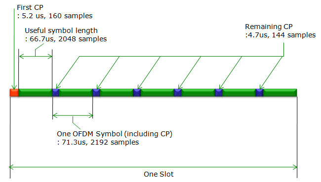
< Cyclic Prefix Overhead >Following is the detailed symbol structure of LTE downlink symbol structure within a slot (half subframe). In terms of symbol structure, one LTE radio frame is made up of 20 of this tructure. As you see here, every OFDM symbol has its own cyclic prefix. Even though this cyclic prefix plays important roles in current LTE waveform as described in OFDM : Cyclic Prefix page, strictly speaking it is a kind of overhead. Just by simple calculation, you would notice the overhead is around 7.6 % (=160/(160+2014)) in case of the first OFDM in a slot and is around 6.6 %((=144/(144+2014)) in other OFDM symbols.
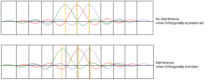
Can we completely remove this cyclic prefix in 5G Waveform ? Some of the 5G waveform candidates (e.g, FBMC) tries to completely remove it, but many of the Candidate still use the cyclic prefix with various length. < Poor Tolerance to Inter subcarrier interference (Poor tolerance to broken orthogonality) >Currently LTE's OFDM is based on the assumption that all the subcarries are strictly orthogonal to each other as shown in the upper plot in following figure. There would be serious performance degrade when the orthogonality gets broken as shown in lower plot.
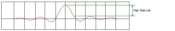
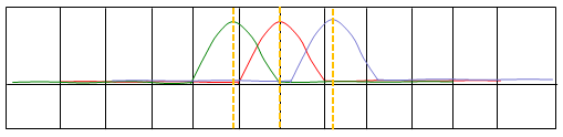
< Large PAPR (Peak to Averate Power Ratio) >Due to this, it requires high linearity for output power amplifier. This reduces UE power amplifier efficiency and increase energy consumption. (Ref [6]) < High Out of Band Sidelobes >This would cause interference with adjacent frequency and reduce the spectral efficiency of the adjacent carrier. Also when multiple UEs are operating at the same location, this high Out of Band Sidelobes can cause serious interference issues. (Ref [6]) Improvement in 5G WaveformIn this section, I will describe on characteristics of 5G Waveform candidate in terms of how these contribute to reducing the problems we are facing in current LTE waveform described above. < Tolerance to Poor Orthgonality >Before we look into the new waveform, let's see what kind of problem we have with the current OFDM waveform. As you know, the current OFDM symbol is made up of sub carriers that looks as follows. The first obvious problem of this subcarrier is that it has pretty big side lobes as shown below. This is a kind of leakage of spectrum (energy loss) and this leakage can act as source of interference to neighbouring subcarriers.
To reduce the effect of interference of a sub carrier on neighbouring sub carrier, it is strictly required that the space between the sub carrier be strictly determined in such a way that each sub carrier is orthogonal to each other. As long as the orthogonality maintained as shown below, we can minimize the interference between sub carriers at least at the sampling point as shown in the upper track of the following graph. But life does not always go as we want. There are many cases where the sub carrier spacing drifts and orthogonality get broken. In that case, these subcarrier would see interference as shown in the lower track of the following graph.
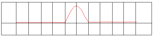
Is there any way to solve (at least improve) the problems described above ? There has been several different techniques that would reduce these problem. Even though each of these techniques are different from each other in terms of details, the basic idea is similar. The basic idea is to use sub carrier shaped as shown below. As you see here, you see no (or negligible) amount of sidelobe.
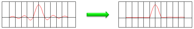
With this sub carrier waveform, the problem of interference among sub carrier will be greatly reduced even when the orthogonality between sub carriers are not maintained as shown below and also spectrum leakage will greatly be redueced as well.
Now the questions is how to convert the current waveform (shown on left) into the new form (shown on right)
There are several different technologies proposed, but the most common concept is to design a specific filter and perform filtering to each sub carrier or a group of sub carriers (sub-band) as illustrated below.
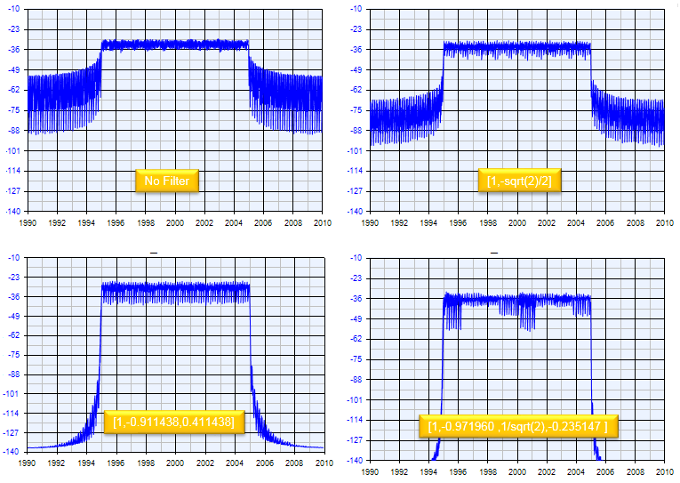
Depending on what kind of filters to be used and how they will be applied (applied to each sub carriers ? or applied to a group of sub carriers) and some other factors, several different technologies are proposed. The main purpose of this page is to introduce the overal concept of these technology. However, it will take pretty long time for me to complete this page and you can search some technical papers on your own if you are really interested in this area. < Improved Sideband (Out of Band) Performance >In addition to the strength (tolerance) to poor orthogonality, filtering the subcarrier (or subchannel) will produce another very positive effect. As shown below, the out-of-band performance of the transmittion band highly improves as subcarrier filter is applied and the number of filter order gets larger. This improved sideband performance will result in improved coexistance characteristics with other Radio Access Technology (e.g, the conventional LTE) or with signals for adjacent users/services. (Following is from the FBMC simulation output from SystemVue(Keysight))
< OFDM in Uplink >Now most of the readers would know that we use different waveform in downlink and uplink in LTE (4G), OFDMA in Downlink and SC-FDMA in Uplink. Also, the readers would understand why they decided to use SC-FDMA in Uplink. Main motivation for SC-FDMA is to reduce PAPR (Peak to Average Power Ratio) and to increase energy efficiency as well on UE side. However, there are some drawbacks for using SC-FDMA. First drawback is that it is more complicated to implement comparing to OFDMA and not so flexible in terms of scheduling(resource allocation). However, in 5G the simple implementation and scheduling flexibility is not something to be sacrificed easily. So in R1-163223(Ref [7]), it is proposed to use OFDM in uplink as well. Of course, we will have some drawbacks with the adoption of OFDM in Uplink, so we need to come up with any form of solutions for these drawbacks. Some of the possible solution were also suggested in R1-163223. Common CandidateIt is not decided yet exactly what kind of waveform will be used in 5G, but followings are some of the candidates that are proposed and tried by various parties. I think one of the best describing documents summarizing each of these waveform would be R1-162199 (Ref [8])
Criteria for Waveform SelectionWe have seen several different Waveform Candidate for 5G. Now you may ask 'Why we don't have only one best candidate in stead of multiple different candidate ?'. It is because there are several different criteria (KPI : Key Performance Indicator) for waveform selection and it is hard to find any single candiate which is the best fit for all of these criteria. Followings are some of the criteria for waveform selection mentioned in Ref [5] and in R1-163222 (Ref [9]). I don't think there would be any single waveform that best meet all of these criteria. So it is highly likely to come up with multiple different waveforms which best meets a subsets of these criteria and adopt the multiple candidates depending on use-cases. We don't know yet which waveform will be selected for 5G.. we may see a couple of different waveforms in real 5G depending on use case.
< Spectral Efficiency >Spectral efficiency indicates 'how many bits you can transmit per one Hz'. High spectral efficiency implies high throughput with the same bandwidth. Since one of the biggest goal for 5G is to achieve super high throughput, so high spectral efficiency can be an important criteria. This criteria is especially important in lower frequency than in higher frequency (mmWave Range), because we don't have much free spectrum in lower frequency. To achieve high throughput with narrow spectrum is to increase spectrum efficiency. However, in higher frequency(in mmWave) we can just use wide bandwidth to achieve high throughput. < Multi-user support, multi-antenna (MIMO) support >In 5G, they will use almost every possible types of MIMO and multi antenna technology (e.g, Single User MIMO, Multi User MIMO, Massive MIMO, BeamForming etc). The candiate waveform should support these capability with minimum complexity. < Low Cubic Metric >Low Cubic Metric is required to compensate for power amplifier's inefficiency. This will be especially important for Uplink transmission, D2D and low cost devices. < Robustness to channel time-selectivity >This would be important criteria for high speed/high mobility and large cell scenario. It means this might not be the tight criteria for very high frequency, because it is not highly likely to use very high frequency for large cell and high mobility situation. Due to poor propagation properties of high frequency signal, high frequency is more likely to be used for small cell/non-mobility scenario. One exception would be V2V (Vehicle to Vehicle) communication. In this case, it is likely to use high frequency but the transmitter & recievers are in high mobility. < Robustness to channel frequency-selectivity >This property will be espeically important for multi-path scenario. It is also important to maitain good channel frequency-selectivity regardless of deployment type, beamforming technology and bandwidth.
Reference[1] GFDM Interference Cancellation for Flexible Cognitive Radio PHY Design R. Datta, N. Michailow, M. Lentmaier and G. Fettweis Vodafone Chair Mobile Communications Systems, Dresden University of Technology, 01069 Dresden, Germany Email:[rohit.datta, nicola.michailow, michael.lentmaier, fettweis]@ifn.et.tu-dresden.de [2] 5G NOW. D3.1 5G Waveform Candidate Selection [3] Waveform Contenders for 5G - suitability for short packet and low latency transmissions. Frank Schaich, Thorsten Wild, Yegian Chen Alcatel-Lucent AG Bell Labs Stuttgart, Germany [4] FBMC Physical Layer : a Primer PHYDYAS [5] Will 5G say farewell to OFDM? [6] 5G - New Waveform Signal Analysis [7] 3GPP R1-163223. 3GPP TSG RAN WG1 Meeting #84bis - Using OFDM in NR [8] 3GPP R1-162199. 3GPP TSG RAN WG1 Meeting #84bis - Waveform Candidates [9] 3GPP R1-163222. 3GPP TSG RAN WG1 Meeting #84bis - Waveform for NR [10] TWS 2015: Is OFDM Dead? An Overview of Candidate Waveforms for 5G [11] 5G Waveform Candidates - Application Note ( Rohde-Schwarz )
|
||