While LTE is mainly designed for broadband application, NR is designed for accomodating various application including broadband, mMTC and URLLC all in the single protocol. So the QoS architecture is more flexible (probably more difficult to understand ?) to provide appropriate service for all those application. One obvious difference you may notice is to compare LTE QCI and NR 5QI table, and just compare the length of the tables.
- QoS Structure
- QoS Mapping in Signaling Message
- Mapping between IP packet and QoS Pipe
- QoS Parameters
QoS Structure
In fact, the QoS is determined / affected by almost every components involved in the communication between the parties of the commication, but major players determining QoS is those components on the bold lines in the UE + Network architecture shown below. Those components are UE, AN(RAN, gNB), UPF (User Plane Function), DN(Data Network). In this illustration, I illustrated a specific sample case of QoS flow so that you can make more tangible sense out of it.
As shown below, the user data would flow from a source (DN in this case) and final destination (UE in this case). Each of the data packet goes though a specific PDU and Data Radio Bearer(DRB). Within these pipe line can be one or more imaginary flow with different level of priority, data rate, latency etc. These imaginary flow is called a QoS Flow. Each of those QoS flow would be eventually mapped to a specific items in 5QI table. In order to meet the requirement in the selected 5QI, network need to configure all the elements from wireless physical resources through all the physical resources on core network interfaces.
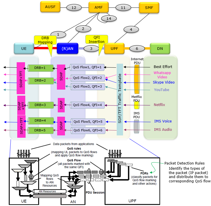
Source : Reconstructed based on 3GPP 23.501 and 5G Quality of Service (DEVOPEDIA)
The NR QoS be illustrated in other way as well illustrated by Rahim Navael as shown below. Rahim kindly approved me to share the illustration in my note.
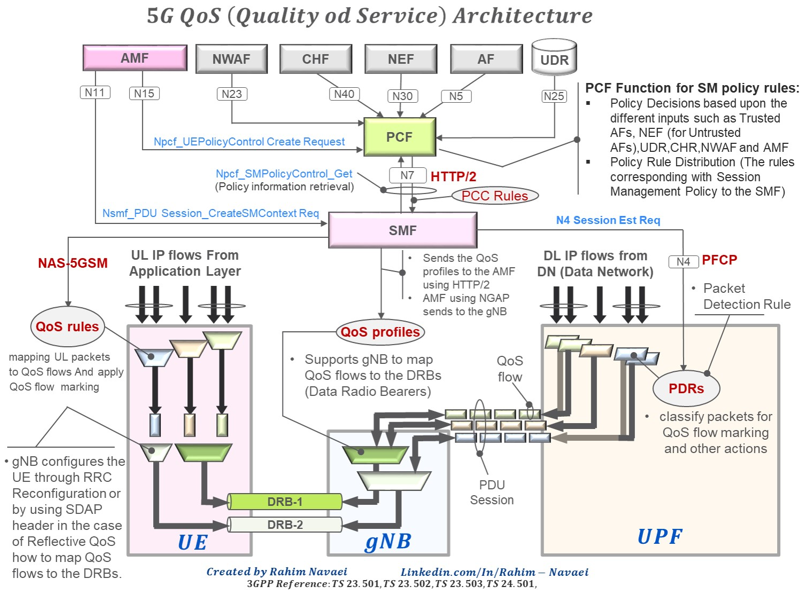
Image Source : Rahim Navaei's linked in post
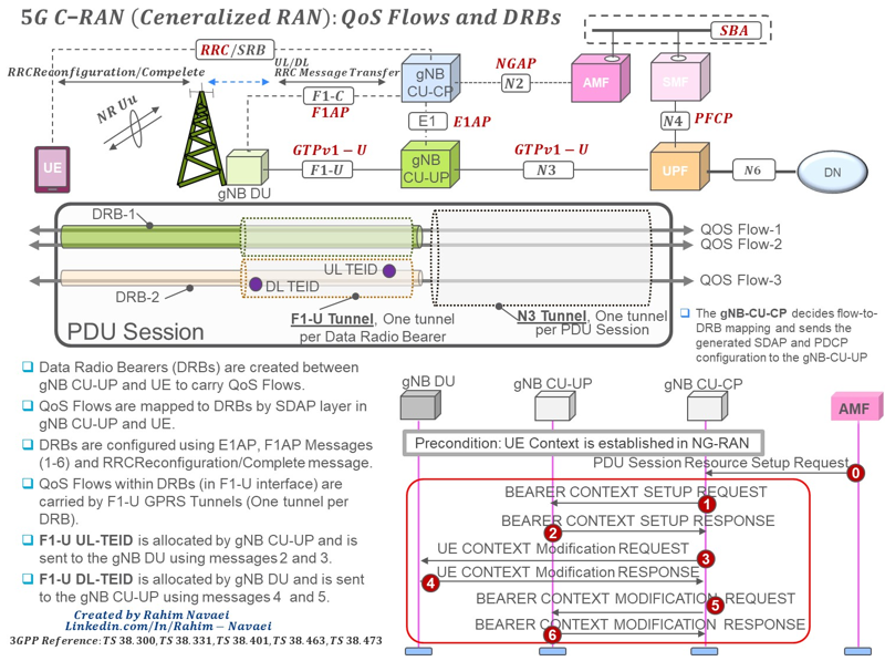
Image Source : Rahim Navaei's linked in post
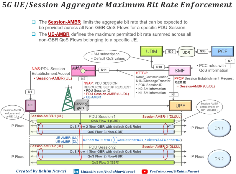
Image Source : Rahim Navaei's linked in post
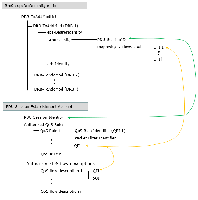
QoS Mapping in Signaling Message
QoS is applied for each data stream all the way from wireless physical layer through the every core network sitting on the data path. As mentioned above, the most fundamental units of QoS is QoS Flow. But the QoS flow is a logical pipeline defined for core network flow (more specifically for the data flow between AN(gNB) and UPF, in other words N3 interface). For the wireless part, the data flow is managed in different flow called DRB(Data Radio Bearer). To make a complete QoS pipe from the source of the data through the final destination, there should be some link (mapping) connecting the core network QoS pipe (i.e, QoS Flow) and AN pipe (i.e, DRB), and these mapping need to be informed to UE via signaling message. The signaling message getting involved in the creation and mapping of QoS pipe is illustrated below. The creation (definition) of QoS pipe on core network side is done by PDU Session Establishment Accept and the mapping between the core network QoS pipe and Wireless QoS Pipe(DRB) is done by SDAP configuration in a Rrc message (RrcSetup or RrcReconfiguration). The Indicator (Identification) that connect the whole QoS pipe at every level is called QFI (QoS Flow Identifier).
Mapping between IP packet and QoS Pipe
In what has been described above, how a QoS pipe is created and what the QoS pipe is made up of is relatively well described. But how various type of original user data (IP packet in most case) is mapped to different type of QoS pipe is not explained in detail. For example, Take a look at the illustration shown at the beginning of this page. If you start streaming a YouTube, at first the packet goes through the internet PDU and within the internet PDU the packet should map to QoS Flow3. Then you may ask 'how the YouTube IP packet is directed (mapped) to QoS Flow3'. You would have similar questions in Uplink IP Packet as well. This mapping is done in both downlink and uplink IP packet as described below.
- By signaling message : Network can inform UE of QoS rules in NAS messages PDU Session Establishment / Modification procedure
- Pre-configured in the UE or implicitly derived by the UE by applying Reflective QoS
A QoS rule contains the QFI of the associated QoS Flow, a Packet Filter Set and a precedence value as shown in the following example.
QoS rule 1:
QoS rule identifier = 1
Rule operation code = 1 (create new QoS rule)
DQR = 1 (the QoS rule is the default QoS rule)
Number of packet filters = 1
Packet filter direction = 3 (bidirectional)
Match-all
QoS Parameters
There are many different Parameters that are involved in NR QoS. According to 23.501-5.7.2, following is the list of the NR QoS parameters. Some of these parameters are pretty straightforward to understand (e.g, 5QI, Bit Rates, Packet Loss Rate) but I would need some more time to get clear understandings on some other parameters (e.g, ARP, RQA, Notification Control).
- 5QI
- ARP (Allocation and Retention Priority)
- RQA (Reflective QoS Attribute)
- Notification Control
- Flow Bit Rates
- Guaranteed Flow Bit Rate (GFBR)
- Maximum Flow Bit Rate (MFBR)
- Aggregate Bit Rates
- per Session Aggregate Maximum Bit Rate (Session-AMBR)
- per UE Aggregate Maximum Bit Rate (UE-AMBR)
- Maximum Packet Loss Rate
Many of those parameters are explcitely specified in signaling messages when a QoS pipe is created. Following example of PDU Session Establishment Accept message shows QoS parameters in it (This is a sample message from the log provided by Amarisoft)
Example 01 >
I tried to list all the important (relavent) messages in RRC, NAS, NGAP which are related to QoS setup and some data packets. Try to follow through the messages and draw a mapping diagram on your own.
Message: 127.0.1.100:38412 PDU session resource setup request
initiatingMessage: {
procedureCode id-PDUSessionResourceSetup,
criticality reject,
value {
protocolIEs {
{
id id-AMF-UE-NGAP-ID,
criticality reject,
value 100
},
{
id id-RAN-UE-NGAP-ID,
criticality reject,
value 1
},
{
id id-PDUSessionResourceSetupListSUReq,
criticality reject,
value {
{
pDUSessionID 1,
pDUSessionNAS-PDU '7E02AB8A6BEE047E00680100772E0105C2110009....'H,
s-NSSAI {
sST '01'H
},
pDUSessionResourceSetupRequestTransfer {
protocolIEs {
{
id id-PDUSessionAggregateMaximumBitRate,
criticality reject,
value {
pDUSessionAggregateMaximumBitRateDL 5000000000,
pDUSessionAggregateMaximumBitRateUL 2000000000
}
},
{
id id-UL-NGU-UP-TNLInformation,
criticality reject,
},
{
id id-PDUSessionType,
criticality reject,
value ipv4
},
{
}
}
}
}
}
}
}
},
{
id id-UEAggregateMaximumBitRate,
criticality ignore,
value {
uEAggregateMaximumBitRateDL 5000000000,
uEAggregateMaximumBitRateUL 2000000000
}
}
}
}
}
Protocol discriminator = 0x7e (5GS Mobility Management)
Security header = 0x2 (Integrity protected and ciphered)
Auth code = 0xab8a6bee
Sequence number = 0x04
Protocol discriminator = 0x7e (5GS Mobility Management)
Security header = 0x0 (Plain 5GS NAS message, not security protected)
Message type = 0x68 (DL NAS transport)
Payload container type = 1 (N1 SM information)
Payload container:
Protocol discriminator = 0x2e (5GS Session Management)
Procedure transaction identity = 5
Message type = 0xc2 (PDU session establishment accept)
Selected PDU session type = 0x1 (IPv4)
Selected SSC mode = 0x1 (1)
5GSM cause = 0x32 (PDU session type IPv4 only allowed)
PDU address:
SI6LLA = 0
PDU session type = 1 (IPv4)
IPv4 = 192.168.3.2
S-NSSAI:
Length of S-NSSAI contents = 1 (SST)
SST = 0x01
Mapped EPS bearer contexts:
Mapped EPS bearer context 1:
EPS bearer identity = 5
Operation code = 1 (create new EPS bearer)
E = 1 (parameters list is included)
Number of EPS parameters = 2
Mapped EPS QoS parameters:
QCI = 9
APN-AMBR:
APN-AMBR for downlink = 4864000000 bits
APN-AMBR for uplink = 1792000000 bits
Extended protocol configuration options:
Ext = 1
Configuration protocol = 0
Protocol ID = 0x8021 (IPCP)
Data = 03 00 00 0a 81 06 08 08 08 08
Protocol ID = 0x000d (DNS Server IPv4 Address)
Data = 8.8.8.8
DNN = "internet.mnc001.mcc001.gprs"
PDU session ID = 1
message c1:
rrc-TransactionIdentifier 0,
criticalExtensions rrcReconfiguration: {
radioBearerConfig {
srb-ToAddModList {
{
srb-Identity 2
}
},
drb-ToAddModList {
{
},
drb-Identity 1,
pdcp-Config {
drb {
discardTimer infinity,
pdcp-SN-SizeUL len18bits,
pdcp-SN-SizeDL len18bits,
headerCompression notUsed: NULL,
statusReportRequired true
}
}
}
}
},
Message: 127.0.1.100:38412 PDU session resource setup response
successfulOutcome: {
procedureCode id-PDUSessionResourceSetup,
criticality reject,
value {
protocolIEs {
{
id id-AMF-UE-NGAP-ID,
criticality ignore,
value 100
},
{
id id-RAN-UE-NGAP-ID,
criticality ignore,
value 1
},
{
id id-PDUSessionResourceSetupListSURes,
criticality ignore,
}
}
}
}
}
}
}
}
}
Message: 127.0.1.100:2152 G-PDU
Data:
0000: 34 ff 00 44 3c e0 4e cc 00 00 00 85 01 10 01 00 4..D<.N.........
0010: 45 00 00 3c db 6e 40 00 40 11 8b 88 c0 a8 03 02 E..<.n@.@.......
0020: 08 08 08 08 2a 84 00 35 00 28 df a2 92 e0 01 00 ....*..5.(......
0030: 00 01 00 00 00 00 00 00 03 77 77 77 06 67 6f 6f .........www.goo
0040: 67 6c 65 03 63 6f 6d 00 00 01 00 01 gle.com.....
Message: 127.0.1.100:2152 G-PDU
Data:
0000: 34 ff 00 63 3d 0c 6c 10 00 00 00 85 01 00 01 00 4..c=.l.........
0010: 45 00 00 5b d4 b4 00 00 78 11 9a 23 08 08 08 08 E..[....x..#....
0020: c0 a8 03 02 00 35 74 05 00 47 49 22 f8 08 81 80 .....5t..GI"....
0030: 00 01 00 01 00 00 00 00 11 63 6f 6e 6e 65 63 74 .........connect
0040: 69 76 69 74 79 63 68 65 63 6b 07 67 73 74 61 74 ivitycheck.gstat
0050: 69 63 03 63 6f 6d 00 00 01 00 01 c0 0c 00 01 00 ic.com..........
0060: 01 00 00 00 7e 00 04 8e fb 20 43 ....~.... C
Reference
- 5G Quality of Service
- 5G NR QoS Architecture, QoS Attribute and QoS Flow
- Learn about QoS in 5G Networks by Paul Shepherd
- Qos in 5G (Quality of service in 5G) - Part 1 (YouTube)
- Qos in 5G (Quality of service in 5G) - Part 2 (YouTube)
- QoS (Quality of Service) in 5G (YouTube)
- SERVICE DATA ADAPTATION PROTOCOL (SDAP) (YouTube)
- 3GPP 38.300 - NR and NG-RAN Overall description; Stage-2 => Chapter 12
- 3GPP 23.501 - 5G;System architecture for the 5G System (5GS) => Section 5.7
- 3GPP 24.501 - 5G;System architecture for the 5G System (5GS) => Section 9.11.4.12 ~ 9.11.4.14
- 3GPP 38.413 - 5G; NG-RAN;NG Application Protocol (NGAP) => Section 8.2