|
CORESET in a Nutshell
- CORESET stands for COntrol REsourceSET.
- As the name implies, CORESET is a physical resources that is designed to transmit PDCCH/DCI.
- It corresponds to control region in LTE subframe, but the difference is that frequency domain resource allocation in 5G Coreset is configurable whereas in LTE the contron region always takes up the full channel bandwidth.
- The frequency domain resource allocation of CORESET is configured as a bitmap in RRC
- Time domain resource allocation of CORESET is configured in RRC (in LTE, Time Domain Resource is configured by a specific physical channel called PCFICH)
- As in LTE, a CORESET is made up of subunits which are REG, CCE and Aggregation Level.
- A REG(Resource Element Group) is made up of multiple RE(Resource Element), a CCE is made up of multiple REG and an Aggregation Level is made up of one or multiple CCEs.
- Larger Aggregation Level uses more physical resources to transmit the same information (i.e, DCI) but is more reliable.
|
CORESET in Detail
Resource Allocation Unit in NR is similar to LTE case, but a few new units (e.g, REG bundle, CORESET) are introduced in NR. Basic definition of these units and relationship among these units are described in 38.211 - 7.3.2.2 Control-resource set (CORESET)
CORESET is a set of physical resources(i.e, a specific area on NR Downlink Resource Grid) and a set of parameters that is used to carry PDCCH/DCI. It is equivalent to LTE PDCCH area (the first 1,2,3,4 OFDM symbols in a subframe). But in LTE PDCCH region, the PDCCH always spread across the whole channel bandwidth, but NR CORESET region is localized to a specific region in frequency domain.
Some background of adopting this kind of design is briefly described in IV-A of this paper as follows
Legacy LTE control channels are always distributed across the entire system bandwidth, making it difficult to control
intercell interference . NR PDCCHs are specifically designed to transmit in a configurable control resource set (CORESET). A CORESET is analogous to the control region in LTE but is generalized in the sense that the set of RBs and the set of OFDM symbols in which it is located are configurable with the corresponding PDCCH search spaces. Such configuration flexibilities of control regions including time, frequency, numerologies, and
operating points enable NR to address a wide range of use
cases.
As mentioned above, CORESET in NR is equivalent to the Control Region in LTE. The main difference between CORESET and LTE Control Region can be illustrated as follows.
As you may notice, the control region in LTE spreaded across the whole channel band width(CBW) and NR CORESET is localized within each BWP.
Frequency Domain Parameter : Since Control Region in LTE is always spreaded across the whole channel band width, there is no parameters defining the frequency domain region for LTE control region, but in NR we need a parameter defining the frequency domain width for CORESET since the frequency domain
width
can be set in any value in the multiples of 6 RBs.
Time Domain Parameter : Both NR CORESET and LTE Control Region can vary in time domain length. So we need the parameter for time domain length both in LTE in NR. In LTE, the time domain length of control region is defined by the physical channel called PCFICH but in NR the time domain length of
CORESET
is defined by the RRC parameter (ControlResourceSet.duration).

A CORESET is made up of multiple levels of sub-structures illustrated below. Roughly speaking, you may say 'A CORESET can accommodate multiples of Aggregation Level. An Aggregation Level is made up of N CCE. A CCE is made up of 6 REGs. A REG is made up of 1 RB and 1 OFDM Symbol.'
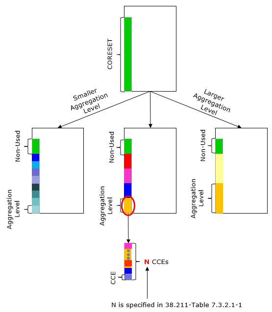
NOTE : Non-Used region is the region that is not covered by Aggregation Levels. There may or may not be such a non-used region depending on configuration. The number of Aggregation Leves for each size can be 0 or multiples and it is specified by Rrc Parameter nrofCandidates
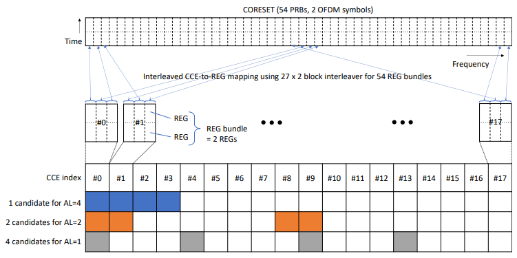
I got another figure that visualize well the mapping between PDCCH and CORESET from Understanding the Heart of the 5G Air Interface: An Overview of Physical Downlink Control Channel for 5G New Radio (NR) . Basically this shows the samething as my diagram shown above. One major difference is that
this shows the case of interleaving whereas my diagram shown above is assumed for the case of non-interleaving.
Followings are basic terminilogies that you need to understand the CORESET resource allocation and monitoring process.
Resource Element : This is same as LTE. It is the smallest unit of the resource grid made up of one subcarrier in frequency domain and one OFDM symbol in time domain.
Resource Element Group (REG) : One REG is made up of one resource block (12 resource element in frequency domain) and one OFDM symbol in time domain. For clarification, I quote 38.211-7.3.2.2 as below :
A control-channel element consists of 6 resource-element groups (REGs) where a resource-element group equals one resource block during one OFDM symbol.
REG Bundles : One REG bundle is made up of multiple REGs. The bundle size is specified by the parameter 'L'. The L is determined by the RRC parameter reg-bundle-size.
Control Channel Element(CCE) : A CCE is made up multiple REGs. The number REG bundles within a CCE varies.
Aggregation Level : Aggregation Level indicates how many CCEs are allocated for a PDCCH. Aggregation Level and the number of allocated CCE is defined in following table. (LTE has similar mapping between Aggregation Level and the Number of CCEs as described
here )
< 38.211-Table 7.3.2.1-1: Supported PDCCH aggregation levels. >
|
Aggregation Level
|
Number of CCEs
|
|
1
|
1
|
|
2
|
2
|
|
4
|
4
|
|
8
|
8
|
|
16
|
16
|
Control Resource Set(CORESET): A CORESET is made up of multiples resource blocks (i.e, multiples of 12 REs) in frequency domain and '1 or 2 or 3' OFDM symbols in time domain. Defined in 38.211 - 7.3.2.2 Control-resource set (CORESET). CORESET is equivalent to the control region in LTE subframe. In LTE, the frequency domain of the control region is always same as the total system bandwidth, so no parameter is needed to define the frequency domain region for
LTE control
region. Time domain region can be {1,2,3} which is determined by PCFICH. However, in NR both frequency region and time domain region can be defined by RRC signaling message.
|
Parameter
|
Description
|
|

|
Number of RBs in frequency domain in a CORESET. Determined by RRC Parameter CORESET-freq-dom
|
|

|
Number of symbols in time domain in a CORESET. Determined by RRC Parameter CORESET-time-dur. This can be 1 or 2 or 3, but 3 is possible only when DL-DMRS-typeA-pos = 3
|
|

|
Number of REGs in a CORESET
|
|
L
|
REG Bundle Size, set by CORESET-REG-bundle-size
|
The RRC parameters defining the CORESET are as follows (based on 38.331 v15.3.0) :
ControlResourceSet ::= SEQUENCE {
controlResourceSetId ControlResourceSetId,
frequencyDomainResources BIT STRING (SIZE (45)),
duration INTEGER (1..maxCoReSetDuration),
//maxCoReSetDuration = 3
cce-REG-MappingType CHOICE {
interleaved SEQUENCE {
reg-BundleSize ENUMERATED {n2, n3, n6},
interleaverSize ENUMERATED {n2, n3, n6},
shiftIndex INTEGER(0..maxNrofPhysicalResourceBlocks-1)
},
nonInterleaved NULL
},,
precoderGranularity ENUMERATED {sameAsREG-bundle, allContiguousRBs},
tci-StatesPDCCH SEQUENCE(SIZE (1..maxNrofTCI-StatesPDCCH)) OF TCI-StateId
tci-PresentInDCI ENUMERATED {enabled} OPTIONAL
pdcch-DMRS-ScramblingID BIT STRING (SIZE (16)) OPTIONAL
}
controlResourceSetId : this corresponds to L1 parameter 'CORESET-ID'
- Value 0 identifies the common CORESET configured in MIB and in ServingCellConfigCommon
- Values 1..maxNrofControlResourceSets-1 identify CORESETs configured by dedicated signalling
- The controlResourceSetId is unique among the BWPs of a ServingCell.
frequencyDomainResources: Frequency domain resources (this should be within BWP assigned to UE). This corresponds to L1 parameter L1 parameter 'CORESET-freq-dom'.
- Each bit corresponds a group of 6 RBs, with grouping starting from PRB 0, which is fully contained in the bandwidth part within which the CORESET is configured.
- The most significant bit corresponds to the group of lowest frequency which is fully contained in the bandwidth part within which the CORESET is configured, each next subsequent lower significance bit corresponds to the next lowest frequency group fully contained within the bandwidth part within which the CORESET is configured, if any. Bits corresponding to a group not fully
contained
within the bandwidth part within which the CORESET is configured are set to zero.
duration : Contiguouse time duration of the CORESET in number of symbols
cce-reg-MappingType : Mapping method of Control Channel Elements (CCE) to Resource Element Groups (REG).
reg-BundleSize: The number of REGs within a REG Bundle. Corresponds to L1 parameter 'CORESET-REG-bundle-size'
interleaveSize : Corresponds to L1 parameter 'CORESET-interleaver-size'
shiftIndex : Corresponds to CORESET-shift-index
precoderGranularity: Precoder granularity in frequency domain. It corresponds to L1 parameter 'CORESET-precoder-granuality.
tci-StatesPDCCH : Reference to a configured TCI State providing QCL configuration/indication for PDCCH
tci-PresentInDCI : Corresponds to L1 parameter 'CORESET-precoder-granuality'
pdcch-DMRS-ScramblingID : PDCCH DMRS scrambling initalization
Here is an example showing to procedure to map from RE to CCE. For simplicity, I assume that interleaving is not applied.

The coreset described above is normal coreset and those coreset are configured by RRC. But there is a special type of coreset called CORESET 0. This coreset is the one transmitting PDCCH for SIB1 scheduling. As you would notice above, there are many parameters involved in defining those coreset and those parameters are specified by RRC message (e.g, LTE RRC Connection Reconfiguration
for ENDC, SIB1 or RRC Setup in SA). However, CORESET 0 cannot be specified by RRC since it should be used before any RRC is transmitted. It implies that CORESET 0 should be configured by some predefined process and predefined parameters. These predefined process and parameters are summarized as follows.
|
Parameters
|
Predefined value or process
|
|
Frequency/Time Resourece Allocation
|
MIB pdcch-ConfigSIB1 (38.213-13)
|
|
Interleaving
|
Assumed Interleaving (38.211-7.3.2.2)
|
|
L (REG Bundle Size)
|
6 (38.211-7.3.2.2)
|
|
R (Interleaver Size)
|
2 (38.211-7.3.2.2)
|
|
n_shift (Shiftindex)
|
N_cellID (38.211-7.3.2.2)
|
|
Cyclic Prefix
|
Normal (38.211-7.3.2.2)
|
|
Precoding
|
Same Precoding used in REG Bundle (38.211-7.3.2.2)
|
Search Space is an area within a CORESET that UE should monitor to detect a specific PDCCH/DCI. There are two large categories of Search Space(SS) called CSS (Common Search Space) and USS(UE specific Search Space). Which SearchSpace UE has to monitor is defined by RNTI type or RRC configuration summarized below. This summary is based on 38.213-10.1
|
SS Type
|
PDCCH Type
|
RRC Configuration
|
RNTI Type
|
|
CSS
|
Type0-PDCCH
|
pdcch-ConfigSIB1 in MIB
searchSpaceSIB1 in PDCCHConfigCommon
searchSpaceZero in PDCCH-ConfigCommon
|
SI-RNTI
|
|
Type0A-PDCCH
|
searchSpaceOtherSystemInformation in PDCCH-ConfigCommon
|
SI-RNTI
|
|
Type1-PDCCH
|
ra-SearchSpace in PDCCH-ConfigCommon
|
RA-RNTI,TC-RNTI
|
|
Type2-PDCCH
|
pagingSearchSpace in PDCCH-ConfigCommon
|
P-RNTI
|
|
Type3-PDCCH
|
SearchSpace in PDCCH-Config with searchSpaceType = common
|
INT-RNTI, SFI-RNTI, TPC-PUSCH-RNTI, TPC-PUCCH-RNTI, TPCSRS-RNTI, C-RNTI, MCS-C-RNTI, or CS-RNTI
|
|
USS
|
|
SearchSpace in PDCCH-Config with searchSpaceType = ue-Specific
|
C-RNTI, MCS-C-RNTI, SP-CSI-RNTI,CS-RNTI
|
NOTE : For the concept of all search space and comparision among different types of search space, refer to this note.
The answer .. it depends on the size of the SearchSpace. The size of a search space is determined by aggregation level. As in LTE, there are multiple different types of aggregation level, the size of each aggregation level in the unit of CCE is defined in 3GPP as shown below.
< 38.211-Table 7.3.2.1-1: Supported PDCCH aggregation levels. >
|
Aggregation Level
|
Number of CCEs
|
|
1
|
1
|
|
2
|
2
|
|
4
|
4
|
|
8
|
8
|
|
16
|
16
|
Now the question is how big is a search space in the unit of 'bits', not in the unit of CCE. To get the answer for this, we need to understand the detailed resource element structure and some calculation. I found a good note written by Naveen Chelikani and he kindly allowed me for me
to share his writing here.
Aggregation Level 1
- Number of CCE = 1 (6 REG)
- Size of 1 REG in RE = 12
- Total Number of available RE = 12 subcarriers x 1 symbols x 6 REG = 72
- Total number of available PDCCH RE = 72 - 18 = 54 (18 REs are used for DMRS)
- Total number of available bits for the aggregation level = 54 x 2 = 108 bits (2 comes from bits / QPSK)
Aggregation Level 2
- Number of CCE = 2 (12 REG)
- Size of 1 REG in RE = 12
- Total Number of available RE = 12 subcarriers x 1 symbols x 12 REG = 144
- Total number of available PDCCH RE = 144 - 36 = 108 (36 REs are used for DMRS)
- Total number of available bits for the aggregation level = 108 x 2 = 216 bits (2 comes from bits / QPSK)
Aggregation Level 4
- Number of CCE = 4 (24 REG)
- Size of 1 REG in RE = 12
- Total Number of available RE = 12 subcarriers x 1 symbols x 24 REG = 288
- Total number of available PDCCH RE = 288 - 72 = 216 (72 REs are used for DMRS)
- Total number of available bits for the aggregation level = 216 x 2 = 432 bits (2 comes from bits / QPSK)
Aggregation Level 8
- Number of CCE = 8 (48 REG)
- Size of 1 REG in RE = 12
- Total Number of available RE = 12 subcarriers x 1 symbols x 48 REG = 576
- Total number of available PDCCH RE = 576 - 144 = 432 (144 REs are used for DMRS)
- Total number of available bits for the aggregation level = 432 x 2 = 864 bits (2 comes from bits / QPSK)
Aggregation Level 16
- Number of CCE = 16 (96 REG)
- Size of 1 REG in RE = 12
- Total Number of available RE = 12 subcarriers x 1 symbols x 96 REG = 1152
- Total number of available PDCCH RE = 1152 - 288 = 864 (288 REs are used for DMRS)
- Total number of available bits for the aggregation level = 864 x 2 = 1728 bits (2 comes from bits / QPSK)
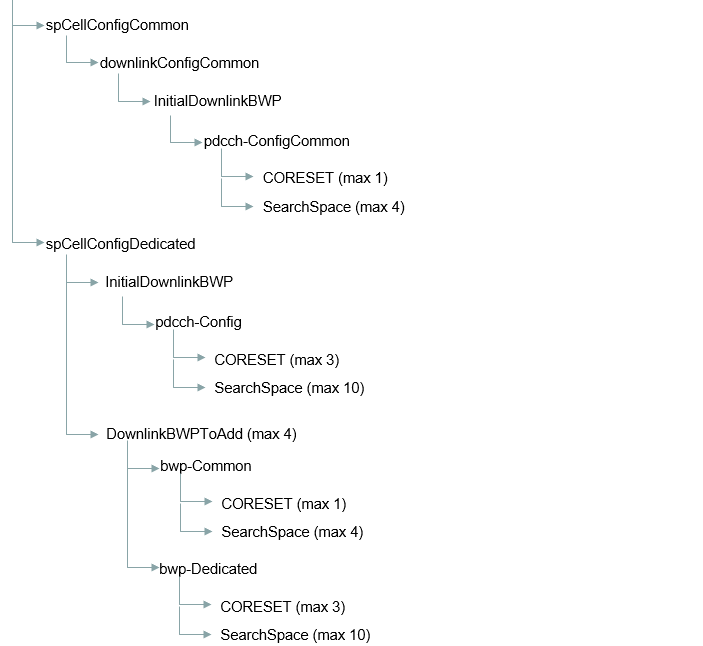
The number of CORESETs within a Channel Band (CBW) depends on how many CORESET/SearchSpaces are configured in a BWP and how many BWPs are configured in the CBW. Followings are ASN structure that I summarized with focus on CORESET/SearchSpace in ENDC.
The answer to this question is dependent on following factors as follows :
- What is the maximum number of DCIs/PDCCHs do you want to allow to send in a slot ? ==> This is determined by the none zero value (i.e, the value other than n0) in SearchSpace.nrofCandidates as shown below.
- How large search space you want to allocate for each DCI/PDCCH ? ==> this is determined by the aggregationLevel with the none zero numbers in SearchSpace parameter.
- How many RBs you want to allocate for each REG/CCE ? ==> This is determined by reg-BundleSize (CCE Size) in ControlResourceSet parameter
- How many number of OFDM symbols you want allocate for CORESET ? ==> This is determined by 'duration' in ControlResourceSet parameter
SearchSpace ::= SEQUENCE {
...
nrofCandidates SEQUENCE {
aggregationLevel1 ENUMERATED {n0, n1, n2, n3, n4, n5, n6, n8},
aggregationLevel2 ENUMERATED {n0, n1, n2, n3, n4, n5, n6, n8},
aggregationLevel4 ENUMERATED {n0, n1, n2, n3, n4, n5, n6, n8},
aggregationLevel8 ENUMERATED {n0, n1, n2, n3, n4, n5, n6, n8},
aggregationLevel16 ENUMERATED {n0, n1, n2, n3, n4, n5, n6, n8}
} OPTIONAL, -- Cond Setup
...
}
ControlResourceSet ::= SEQUENCE {
...
duration INTEGER (1..maxCoReSetDuration),
//maxCoReSetDuration = 3
cce-REG-MappingType CHOICE {
interleaved SEQUENCE {
reg-BundleSize ENUMERATED {n2, n3, n6},
...
},
...
},,
...
}
Number of DCI/PDCCH = 1
Size of a SearchSpace Candidates (AggregationLevel) = 16
Number of SearchSpace Candidates = 1
Number of OFDM Symbols for CORESET = 1
Then minimum number of PRB would be 16 CCE(=16 x 6=96 PRB) within one OFDM symbol and a possible RRC Setting would be as follows.
SearchSpace ::= SEQUENCE {
...
nrofCandidates SEQUENCE {
aggregationLevel1 n0,
aggregationLevel2 n0,
aggregationLevel4 n0,
aggregationLevel8 n0,
aggregationLevel16 n1
} OPTIONAL, -- Cond Setup
...
}
ControlResourceSet ::= SEQUENCE {
...
frequencyDomainResources 11111111111111110000....
duration 1,
cce-REG-MappingType CHOICE {
interleaved SEQUENCE {
reg-BundleSize n6,
...
},
...
},,
...
}
Phy-ParametersFRX-Diff ::= SEQUENCE {
....
multipleCORESET ENUMERATED {supported} OPTIONAL,
...
}
multipleCORESET : Indicates whether the UE supports configuration of more than one PDCCH CORESET per BWP in addition to the CORESET with CORESET-ID 0 in the BWP. It is mandatory with capability signaling for FR2 and optional for FR1.
Reference
[1] 3GPP TSG RAN WG1Meeting NR-AH#3 : R1-1716542 Configuration of CORESET and search space design
[2] 3GPP TSG RAN WG1 Meeting NR#3 : R1-1716564 - Discussion on the CORESET configuration
[3] 3GPP TSG RAN WG1 Meeting NR#3 : R1-1716477 Frequency-first REG bundling for multi-symbol CORESETs
[4] 3GPP TSG RAN WG1 Meeting NR#3 : R1-1716475 Remaining issues related to CORESET configuration
[5] 3GPP TSG RAN WG1 Meeting NR #3 : R1-1716044 Common CORESET design for RMSI scheduling
[6] 3GPP TSG RAN WG1 Meeting NR#3 : R1-1715842 RMSI delivery and CORESET configuration
[7] Understanding the Heart of the 5G Air Interface: An Overview of Physical Downlink Control Channel for 5G New Radio (NR)
- by Kazuki Takeda, Huilin Xu, Taehyoung Kim, Karol Schober∧, and Xingqin Lin#
Qualcomm Inc., Samsung Electronics,∧Nokia, #Ericsson Inc.
|