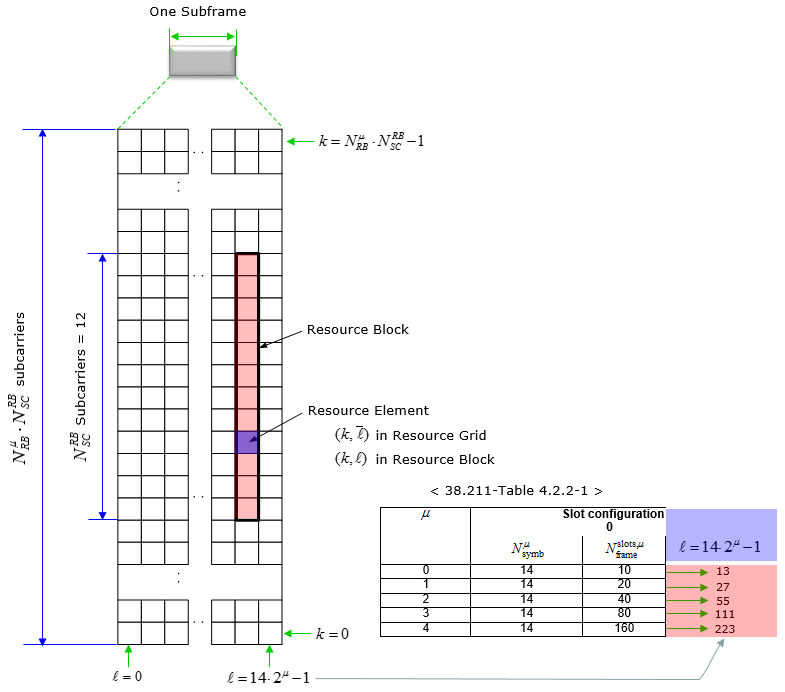
The resource grid for NR is defined as follows. If you just take a look at the picture, you would think it is almost identical to LTE resource grid. But the physical dimmension (i.e, subcarrier spacing, number of OFDM symbols within a radio frame) varies in NR depending on numerology.
- Resource Element and Resource Block
- Resource Grid, Antenna Port and Numerology
- How many Resource Blocks in a Grid ?
- What was added after Release 15
- Reference
Resource Element and Resource Block
Two units sit below the grid. A resource element is a point in time and frequency. A resource block groups twelve of them across frequency, and its extent in time is the part worth reading carefully.
Time domain definition of resource block is a little bit ambiguous. Minimum time domain length in a resource block can be one OFDM symbol, but exact time domain length vary depending SLIV.
One point is worth adding to the paragraphs above. A resource block is counted in more than one way, and the number alone does not say where the block is.
Common resource blocks are numbered across the carrier. Virtual resource blocks are numbered inside a bandwidth part. The same number means a different place in each.
A resource element is identified by a pair : 38.211 writes it (k, l). Here k is the frequency index and l the symbol position.The pair belongs to one grid, not to the cell : it is identified per antenna port and per subcarrier spacing configuration. The same pair names a different element in another grid.Common resource blocks are numbered from 0 upwards : the numbering runs across the frequency domain, per subcarrier spacing configuration.Point A is where the numbering starts : 38.211 calls it the common reference point for the resource block grids.Virtual resource blocks are numbered inside a bandwidth part : they run from 0 within the part. The number means nothing without the part.
Resource Grid, Antenna Port and Numerology
One grid is not enough to describe a cell. The number of grids follows from the antenna ports configured and the numerologies in use. The two multiply rather than add.
- There is one set of resource grids per transmission direction (uplink or downlink) with the subscript set to DL and UL for downlink and uplink
- There is one resource grid for a given antenna port p , subcarrier spacing configuration u, and transmission direction (downlink or uplink).
The word port in antenna port is easy to misread. It is not a physical connector, and two ports do not have to mean two antennas.
An antenna port is a channel property : 38.211 defines it so that the channel carrying one symbol on a port can be inferred from the channel carrying another symbol on it.The grid count multiplies rather than adds : one grid exists per antenna port, per subcarrier spacing configuration and per direction.Each numerology carries its own width : SCS-SpecificCarrier in 38.331 holds carrierBandwidth as INTEGER (1..maxNrofPhysicalResourceBlocks), one per subcarrier spacing in use.Point A lets the grids line up : grids at different numerologies share one reference point. That is what makes them describe a single carrier.
How many Resource Blocks in a Grid ?
The grid has a width, and the specification bounds it at both ends. Both bounds are in the table below. A lower bound exists because a carrier has to be wide enough to be usable. An upper bound exists because the index has to fit the fields that carry it.
The maximum and minimum number of Resource blocks for downlink and uplink is defined as below (this is different from LTE)
< 38.211 Table 4.4.2-1: Minimum and maximum number of resource blocks.>
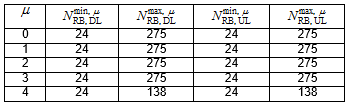
Following is the table that I converted the downlink portions of Table 4.4.2-1 into frequency Bandwidth just to give you the idea on what is the maximum RF bandwidth that a UE / gNB need to support for single carrier.
|
u |
min RB |
Max RB |
sub carrier spacing (kHz) |
Freq BW min (MHz) |
Freq BW max (MHz) |
|
0 |
24 |
275 |
15 |
4.32 |
49.5 |
|
1 |
24 |
275 |
30 |
8.64 |
99 |
|
2 |
24 |
275 |
60 |
17.28 |
198 |
|
3 |
24 |
275 |
120 |
34.56 |
396 |
|
4 |
24 |
138 |
240 |
69.12 |
397.44 |
The minimum is the same at every numerology : 38.211 Table 4.4.2-1 gives 24 resource blocks as the floor in both directions.The maximum is 275 except at the widest spacing : the table gives 275 for numerology 0 to 3, and 138 for numerology 4.275 is a number that appears elsewhere : maxNrofPhysicalResourceBlocks in 38.331 is 275. That is what sizes a resource block bitmap or index.Bandwidth follows from the count and the spacing : a block is 12 subcarriers. The width in Hz is the block count times 12 times the subcarrier spacing.The widest carrier is not at the widest spacing : 138 blocks at 240 kHz give 397.44 MHz. That is 1.44 MHz more than 275 blocks at 120 kHz reach.
What was added after Release 15
The screenshot above is the Release 15 form of the table, and it stops at numerology 4. Two more numerologies exist now, and a reader working on a millimetre wave carrier will meet them. They also changed fields well outside this page.
Release 17 added 480 kHz and 960 kHz subcarrier spacing. Those are numerology 5 and numerology 6. Both appear in the 38.331 SubcarrierSpacing type as kHz480-v1700 and kHz960-v1700.
The SubcarrierSpacing type names all of them : the enumeration reads kHz15, kHz30, kHz60, kHz120, kHz240, kHz480-v1700 and kHz960-v1700.The suffix marks when each arrived : the first five date from Release 15. The two with -v1700 were added in Release 17.The resource block ceiling did not move : maxNrofPhysicalResourceBlocks is still 275, so the grid did not grow in blocks.The table above does not cover them : the block counts for numerology 5 and 6 are in the current 38.211 table, not in the Release 15 screenshot.
The way a width is signalled did not change : SCS-SpecificCarrier still carries carrierBandwidth as INTEGER (1..maxNrofPhysicalResourceBlocks) for every numerology.The two additions are frequency range 2 work : a 480 or 960 kHz subcarrier is only practical where the carrier is wide.A shorter slot widened the timing fields : k0-v1710 in PDSCH-TimeDomainResourceAllocation-r16 is INTEGER(33..128), reaching past the original k0 range of 0 to 32.The uplink and the feedback followed : extendedK2-r17 is INTEGER (0..128), and DL-DataToUL-ACK-r17 holds INTEGER (-1..127) where the Release 15 list stopped at 15.
The reason those fields grew is the slot, not the grid. A slot at 960 kHz is sixteen times shorter than a slot at 60 kHz. The same delay in microseconds therefore spans many more slots, and every field that counts slots had to reach further.
Reference
[1] 38.211 - 5G; NR; Physical channels and modulation. Clause 4.2.2 for the grid, clause 4.4.2 for the block counts and clause 4.4.4.1 for the resource block.
[2] 38.331 - 5G; NR; Radio Resource Control (RRC); Protocol specification. The SubcarrierSpacing type and maxNrofPhysicalResourceBlocks.