In many 5G NR deployments, a UE is anchored on a low-band FDD carrier for reliable uplink coverage, while a mid/high-band TDD carrier is added for huge downlink capacity with massive MIMO. The problem is that the gNB cannot fully exploit DL beamforming on the high band unless it can learn the uplink channel there, because TDD beamforming typically depends on reciprocity and an uplink reference such as SRS. However, the UE may not have enough simultaneous Tx RF chains to keep transmitting on the high band, and the uplink coverage on that band may be too weak for sustained PUSCH. SRS Carrier Switching solves this by letting the UE time-share the same transmitter: it pauses uplink on the source carrier, retunes the RF to the target carrier, transmits an SRS burst only to “sound” the channel, and then retunes back to resume normal operation. This switching creates an unavoidable interruption gap, so the scheduler must avoid UL/DL timing conflicts during the retune window, and it must also apply collision rules where high-priority signals like SR or ACK/NACK can override the planned SRS. This is different from SRS antenna switching, which rotates the Tx chain across antenna ports on the same carrier, while carrier switching moves the same chain across different frequencies, and it also explains why UL CA is not required, because the transmission is sequential rather than simultaneous.
The drawing below puts that time sharing on one timeline. The upper row is the wideband TDD carrier, marked Max 2 Layer, and its slots run D, D, D, S. The lower pair of rows is the narrow FDD carrier, marked Max 1 Layer, with its own uplink row above its downlink row. The bracket on the left labels the whole arrangement DL CA, No UL CA. Follow the blue arrows upward. They mark the moments where the UE leaves the FDD uplink and appears in the purple slivers on the TDD carrier, which are the SRS bursts. The red crosses cover the TDD uplink regions the UE never uses, because no uplink data is carried there at all.
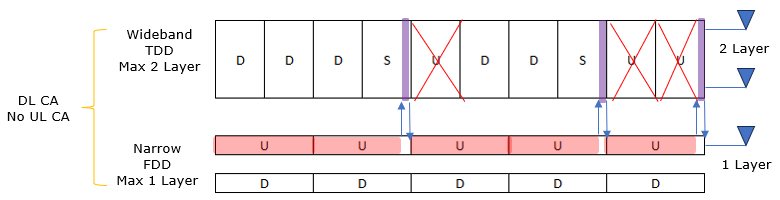
The TDD carrier gives two downlink layers against the FDD carrier’s one, and the only thing the UE ever sends on it is the SRS burst. Everything else in its uplink is crossed out.
- Clearing Up Confusion with other UL switching features
- SRS Carrier Switching vs UL CA
- UE Capability Information
- Example
- What Triggers a Switch ?
- Reference
Clearing Up Confusion with other UL switching features
In NR uplink discussions, terms like UL Tx switching, SUL, SRS antenna switching, and SRS carrier switching often sound like the same idea because they all involve “moving something” in the uplink side, either across frequency or across antenna resources. But the key is to separate the object being switched and the purpose of the transmission. SUL and UL Tx switching are uplink capacity/coverage features, so they exist to carry real uplink traffic, meaning PUSCH and sometimes PUCCH are part of the intention. SRS antenna switching is also a reference-signal driven mechanism, but it stays on the same carrier and mainly rotates limited Tx resources across antenna ports so the gNB can build a better MIMO picture on that band. SRS carrier switching is the special case that looks like inter-carrier uplink activity but is not trying to move any user or control data to the target carrier at all. The UE temporarily retunes only to “probe” the target band by sending SRS, so the gNB can estimate that band’s channel for downlink beamforming, and then the UE immediately returns to its normal uplink carrier. The defining point is that SRS carrier switching is an SRS-only operation on the target carrier, while the other uplink switching features are designed to deliver uplink data or uplink coverage improvement
Why the terms feel similar - All of them involve “switching” behavior on the uplink side.
- The switch can be frequency-related (move Tx to another carrier) or resource-related (reuse limited Tx chains/antennas).
The clean way to de-confuse - Step 1: Check what is being switched: carrier frequency vs antenna port vs uplink path.
- Step 2: Check what is being transmitted: SRS only vs real UL traffic (PUSCH/PUCCH).
- Step 3: Check the goal: downlink MIMO optimization vs uplink coverage/speed.
SRS Carrier Switching - Switching what? Tx chain retunes across different carriers (different frequency CCs).
- What is transmitted on target carrier? SRS only.
- PUSCH/PUCCH on target carrier? No. This is the defining point.
- Main goal: gNB measures the uplink channel on the target band to improve DL beamforming / DL MIMO (typically TDD high band).
- Typical scenario: UE stays UL-reliable on low-band FDD, but gNB wants DL gains on mid/high-band TDD.
SRS Antenna Switching - Switching what? Tx chain cycles across antenna ports on the same carrier.
- What is transmitted? SRS across different ports.
- Main goal: Improve spatial channel knowledge to enable higher-rank DL MIMO on the same band.
- Why it matters: UE may have limited Tx chains but multiple Rx antennas, so it needs to sound multiple spatial paths efficiently.
UL Tx Switching - Switching what? Tx chain retunes across carriers (often FDD ↔ TDD sharing).
- What is transmitted on target carrier? Actual uplink traffic.
- PUSCH on target carrier? Yes. This is the key difference vs SRS carrier switching.
- Main goal: Improve uplink performance (coverage / throughput), often to support more UL layers or better UL utilization on a band.
SUL (Supplementary Uplink) - Switching what? UE uses a different uplink carrier than the downlink carrier (DL on higher band, UL on lower band).
- What is transmitted? Real UL traffic on the SUL carrier (PUSCH/PUCCH as configured).
- Main goal: Improve uplink coverage, especially at cell edge.
The one-sentence differentiator - SRS Carrier Switching: Inter-carrier switch for measurement only (SRS), not for uplink data.
- UL Tx Switching / SUL: Inter-carrier uplink solutions that carry uplink data/control.
- SRS Antenna Switching: Intra-carrier SRS across antennas to improve spatial channel knowledge.
Practical implications - Scheduler view (SRS CS): Target carrier UL is a sounding opportunity, not a traffic pipe.
- Scheduler view (UL Tx Switching / SUL): Must plan for real UL grants, power, HARQ timing, and control conflicts.
Common pitfall - Mistake: Seeing a UE hop to a different carrier and assuming UL CA or UL data on that carrier.
- Reality: For SRS carrier switching, it is TDM probing, not simultaneous UL data.
SRS Carrier Switching vs UL CA
SRS Carrier Switching is used mainly for DL only CA setup only. If it is in DL/UL CA, this switching would not be needed because in UL CA SRS for both carrier is being transmitted without switching. The distinction is worth getting right early, because the two look identical in a log. In both cases the UE sounds a carrier it is not otherwise using for uplink data. What differs is the hardware underneath, and everything else in this section follows from that one difference.
SRS Carrier Switching is mainly used in a DL-only CA setup. In this case, the UE is configured with multiple CCs for downlink reception, but it still uses only one main uplink carrier for real UL transmission. The gNB still wants to run strong DL MIMO and beamforming on the secondary high-band carrier, so it needs uplink sounding on that carrier to estimate the channel. However, since the UE is not transmitting UL on that secondary carrier, there is no “natural” uplink signal there, and the UE may not have enough simultaneous Tx RF chains to transmit uplink on both carriers at the same time. This is why the UE temporarily retunes to the target carrier and transmits SRS only, and then it returns back to the source uplink carrier.
If the deployment is DL/UL CA, the situation changes. In UL CA, the UE can transmit uplink on multiple carriers simultaneously, which implies that the uplink RF chain resources are available to support those carriers at the same time. In that condition, the UE can transmit SRS on each uplink carrier directly as part of the normal UL operation, so the gNB can obtain channel measurements for each carrier without any special retuning procedure. As a result, the “borrow-and-return” mechanism of SRS Carrier Switching is typically not needed, because the UE does not need to time-share a single transmitter to create uplink sounding on the other carrier.
The fundamental logic behind this feature is.
- If you have Uplink CA (DL/UL CA): You have two active transmitters (RF Chains) running simultaneously. You don't need to "switch" or "steal" the transmitter from the FDD band to sound the TDD band—you just use the TDD transmitter that is already active.
- If you have DL-only CA (SRS Switching): You have Downlink on the TDD band, but no Uplink data path. You likely only have one active transmitter (on FDD). To measure the TDD channel, you must briefly "switch" that single transmitter over to TDD.
Here is the comparison to make it concrete.
Scenario 1: Full Uplink CA (No Switching Needed)
- Setup: UE connects to Low Band (FDD) + High Band (TDD).
- Hardware: The UE has 2 separate Power Amplifiers (PAs) active at the same time.
- Behavior:
- FDD Band: Sends Data + SRS.
- TDD Band: Sends Data + SRS.
- Result: The UE sends SRS on the TDD band naturally using its dedicated TDD hardware. No interruption on the FDD band occurs.
Scenario 2: SRS Carrier Switching
- Setup: UE connects to Low Band (FDD) + High Band (TDD).
- Hardware: The UE has only 1 Power Amplifier (PA) (or wants to save battery by only using one).
- Problem: The network wants to send DL data on TDD (Massive MIMO), but the UE has no transmitter turned on there to send the pilot signal (SRS).
- Solution: The UE stops the FDD transmission, retunes that single PA to the TDD frequency, sends the SRS, and retunes back.
Why not just always use UL CA?
If UL CA avoids the "switching gap" and the complexity, why don't we use it everywhere?
- Cost: A UE with 2 simultaneous transmitters (2Tx) is more expensive than a UE with 1 transmitter (1Tx). SRS Carrier Switching allows cheaper phones to still get gigabit speeds on the Downlink.
- Battery: Running 2 Power Amplifiers drains the battery twice as fast. If the TDD Uplink is weak (bad coverage), it's a waste of energy to keep that PA on for data. It's better to keep it off and only pulse it for SRS.
- Coverage: High-band TDD (e.g., 3.5 GHz) often has terrible uplink range. The UE might be able to hear the TDD tower (Downlink), but it can't shout back loud enough for Data (Uplink). However, it can shout back just loud enough for a short SRS burst.
Summary Visual
|
Feature |
Uplink Config |
Hardware Status |
SRS Method |
|---|---|---|---|
|
UL CA |
Uplink on Both Bands |
2 active PAs (Simultaneous) |
Direct transmission (No interruption) |
|
SRS Carrier Switching |
Uplink on Primary Only |
1 active PA (Shared/TDM) |
Tune-away & Return (Interruption on Primary) |
UE Capability Information
In the UE capability report, the UE provides the network with the required switching interruption times and, in newer releases, which other bands in the same band combination are affected during the switch. The network uses this information to schedule appropriate gaps, avoid collisions with uplink data, and apply the correct drop/overlap rules when SRS switching coincides with other transmissions.
Following is based on
BandParameters-v1540 ::=            SEQUENCE {
    srs-CarrierSwitch                   CHOICE {
        nr                                  SEQUENCE {
            srs-SwitchingTimesListNR            SEQUENCE (SIZE (1..maxSimultaneousBands)) OF SRS-SwitchingTimeNR
        },
        eutra                               SEQUENCE {
            srs-SwitchingTimesListEUTRA         SEQUENCE (SIZE (1..maxSimultaneousBands)) OF SRS-SwitchingTimeEUTRA
        }
    }                                                                              OPTIONAL,
    srs-TxSwitch                    SEQUENCE {
        supportedSRS-TxPortSwitch       ENUMERATED {t1r2, t1r4, t2r4, t1r4-t2r4, t1r1, t2r2, t4r4, notSupported},
        txSwitchImpactToRx              INTEGER (1..32)                            OPTIONAL,
        txSwitchWithAnotherBand         INTEGER (1..32)                            OPTIONAL
    }                                                                              OPTIONAL
}
Following is based on
SRS-SwitchingTimeNR ::= SEQUENCE {
    switchingTimeDL         ENUMERATED {n0us, n30us, n100us, n140us, n200us, n300us, n500us, n900us}  OPTIONAL,
    switchingTimeUL         ENUMERATED {n0us, n30us, n100us, n140us, n200us, n300us, n500us, n900us}  OPTIONAL
}
Following is based on
BandParameters-v1730 ::= SEQUENCE {
    -- R1 39-3-2  Affected bands for inter-band CA during SRS carrier switching
    srs-SwitchingAffectedBandsListNR-r17    SEQUENCE (SIZE (1..maxSimultaneousBands)) OF SRS-SwitchingAffectedBandsNR-r17
}

SRS-SwitchingAffectedBandsNR-r17 ::= BIT STRING (SIZE (1..maxSimultaneousBands))
Following is based on
BandCombination-UplinkTxSwitch-v1900 ::= SEQUENCE {
    bandCombination-v1900                    BandCombination-v1900                                                          OPTIONAL,
    -- R1 67-5: Enhanced handling of simultaneous SRS carrier switching and uplink Tx switching
    simultaneousSRS-UplinkTxSwitch-r19       ENUMERATED {max, sum}                                                          OPTIONAL,

    supportedBandPairListNR-v1900            SEQUENCE (SIZE (1..maxULTxSwitchingBandPairs)) OF ULTxSwitchingBandPair-v1900  OPTIONAL,
    uplinkTxSwitchingBandParametersList-v1900 SEQUENCE (SIZE (1..maxSimultaneousBands)) OF UplinkTxSwitchingBandParameters-v1900
                                                                                                                            OPTIONAL
}
It is designed to work together with the switching-time reporting, so the UE includes the same number of entries and in the same order as the corresponding srs-SwitchingTimesListNR. For each inter-band “source–target” switching case represented in the switching-times list, the UE provides a bit string that marks which other bands in the combination are affected by that SRS switch.
The network uses this information to apply the correct dropping rules / timelines when SRS switching overlaps with other uplink activity in the same symbol. For intra-band cases (no true inter-band retune), the UE sets the bit string to all zeros, meaning there are no “other-band” impacts to account for beyond the band itself.
The content is typically split into switchingTimeDL and switchingTimeUL, describing the blocking time seen on downlink reception and uplink transmission respectively. The values are represented in discrete steps such as n0us for 0 µs, n30us for 30 µs, and so on, so the scheduler can treat them as well-defined timing penalties rather than free-form delays.
This IE is signaled per pair of bands per band combination, and the switching-time fields are mandatory when that NR band-pair switching capability is supported; otherwise the fields are absent. The network uses these values to avoid scheduling DL/UL activity during the retune window and to prevent collisions when SRS switching would otherwise overlap with data transmissions.
Example
Everything above says what SRS carrier switching is and why a UE would need it. What it has not shown is the field group that switches the feature on, and that gap is worth closing before the worked configurations arrive. The two examples below come from the Amarisoft TechAcademy test note for this feature. One uses two component carriers and one uses three, and both run the uplink on the PCC only.
The IE is SRS-CarrierSwitching, and it does not sit with the SRS resources. It hangs off UplinkConfig as carrierSwitching, a SetupRelease, so it is configured on a serving cell rather than on an SRS resource set.
Following is based on
SRS-CarrierSwitching ::=            SEQUENCE {
    srs-SwitchFromServCellIndex         INTEGER (0..31)                                     OPTIONAL,   -- Need M
    srs-SwitchFromCarrier               ENUMERATED {sUL, nUL},
    srs-TPC-PDCCH-Group                 CHOICE {
        typeA                               SEQUENCE (SIZE (1..32)) OF SRS-TPC-PDCCH-Config,
        typeB                               SRS-TPC-PDCCH-Config
    }                                                                                       OPTIONAL,   -- Need M
    monitoringCells                     SEQUENCE (SIZE (1..maxNrofServingCells)) OF ServCellIndex
                                                                                            OPTIONAL,   -- Need M
    ...
}

SRS-TPC-PDCCH-Config ::=            SEQUENCE {
    srs-CC-SetIndexlist                 SEQUENCE (SIZE(1..4)) OF SRS-CC-SetIndex             OPTIONAL    -- Need M
}

SRS-CC-SetIndex ::=                 SEQUENCE {
    cc-SetIndex                         INTEGER (0..3)                                      OPTIONAL,   -- Need M
    cc-IndexInOneCC-Set                 INTEGER (0..7)                                      OPTIONAL    -- Need M
}
Two details in that listing are easy to misread. The first is srs-SwitchFromServCellIndex, which names the cell whose uplink gets interrupted, not the cell that gains the SRS. 38.331 puts it plainly: it indicates the serving cell whose UL transmission may be interrupted during SRS transmission on a PUSCH-less SCell. So a value of 0 means the PCC is the carrier whose uplink is suspended. That is exactly what the overview figure at the top of this page draws.
The second is srs-SwitchFromCarrier, an ENUMERATED {sUL, nUL}. Only one of those two values is usable today. The field description for typeA states that SRS carrier switching to SUL carrier is not supported in this version of the specification, which is why a working configuration sets nUL. The spec also gives the target a name worth borrowing: a PUSCH-less SCell.
Example 01 : Periodic, 2CC DL CA, no UL CA
The simplest case that shows the feature working. Two NR cells are aggregated for downlink, uplink data stays on the PCC, and the UE still has to sound the SCC so the gNB can beamform on it. Watch the capability exchange first, because the gNB cannot plan the interruption until it knows how long the retuning takes.
The call flow below runs from attach to steady state. The first half is configuration and happens once. The second half, inside the shaded band, repeats for as long as the configuration stands.
The capability enquiry carries srs-SwitchingTimeRequest because the switching time decides how much PCC uplink has to be given up. Once the reconfiguration lands, the tune-away repeats on its own every 80 slots.
Configuration from the Amarisoft TechAcademy test note for this feature. The field values are that note’s, and the nesting is as 38.331 defines it. This is a configuration summary rather than a raw decoded log.
RRCReconfiguration
  secondaryCellGroup / spCellConfig ...
  sCellToAddModList {
    {
      sCellIndex 1,
      servCellConfigCommon { physCellId 500 }
    }
  }

  -- on the PCC, inside ServingCellConfig / uplinkConfig
  carrierSwitching setup: {
    srs-SwitchFromServCellIndex 0,
    srs-SwitchFromCarrier nUL
  }

  -- on the SCC, inside BWP-UplinkDedicated / srs-Config
  srs-ResourceSetToAddModList {
    { usage codebook },
    { usage antennaSwitching }
  },
  srs-ResourceToAddModList {
    {
      nrofSRS-Ports ports2,
      resourceType periodic: { periodicityAndOffset sl80 }
    }
  }
The SCC is added for downlink only : sCellToAddModList brings in sCellIndex 1, and nothing in its configuration gives it a PUSCH. That is what makes it the PUSCH-less SCell the specification talks about.carrierSwitching sits on the PCC, not on the SCC : srs-SwitchFromServCellIndex 0 points at the cell that will be interrupted. The field lives with the victim rather than with the beneficiary.Two usages are configured, and only one of them travels : codebook sounds the PCC for its own uplink, and antennaSwitching is the set that reaches the SCC.sl80 sets the rhythm : a periodic resource every 80 slots means the PCC uplink is interrupted on a fixed cadence, which is what makes the overhead predictable for the scheduler.ports2 is a UE capability question : the number of SRS ports the UE can drive on the target carrier follows from its antenna switching capability, not from this configuration alone.
Example 02 : Periodic, 3CC DL CA, no UL CA
The second configuration changes one thing only, and that is the point of showing it. A third carrier joins the downlink aggregation, so the UE now has two PUSCH-less SCells to sound rather than one. Everything about the switching mechanism stays where it was.
The call flow below drops the setup half into a single band, because attach and the capability exchange run exactly as they did in Example 01. What is worth following is the steady state underneath it. The UE has one transmitter and two carriers to reach, so it visits them one after the other and returns to the PCC in between.
The mechanism is unchanged and the bill is not. Each carrier costs its own suspend, retune and return, so a third carrier does not split the existing interruption. It adds a second one.
Example 03 : Semi-persistent, activated by MAC CE
Semi-persistent sits between the other two, and it suits a scheduler that wants sounding only some of the time. The resource is configured once and then left dormant. A MAC CE activates it. It then runs on its own period exactly as a periodic resource would, until a second MAC CE deactivates it.
The activation message is the SP SRS Activation/Deactivation MAC CE of 38.321 clause 6.1.3.17. Two of its fields matter here. A/D is set to 1 to activate and 0 to deactivate. SRS Resource Set’s Cell ID names the serving cell holding the set, and for carrier switching that is the PUSCH-less SCell itself.
Only the two ends are signalled. Between them the behaviour is identical to Example 01, which is why the configuration differs from it in one CHOICE and nothing else.
Built from
-- on the SCC, inside BWP-UplinkDedicated / srs-Config
srs-ResourceSetToAddModList {
  {
    srs-ResourceSetId 1,
    srs-ResourceIdList { 1 },
    resourceType semi-persistent: { },
    usage antennaSwitching
  }
},
srs-ResourceToAddModList {
  {
    srs-ResourceId 1,
    nrofSRS-Ports ports2,
    resourceType semi-persistent: { periodicityAndOffset-sp sl80 }
  }
}

-- on the PCC, unchanged from Example 01
carrierSwitching setup: {
  srs-SwitchFromServCellIndex 0,
  srs-SwitchFromCarrier nUL
}
The periodicity still lives in the resource, not in the MAC CE : periodicityAndOffset-sp carries sl80 just as periodicityAndOffset-p did. The MAC CE only decides whether that period is running.The MAC CE names the target cell : SRS Resource Set’s Cell ID points at the SCC, so the activation itself identifies which carrier is about to be sounded.The SUL field has only one useful value here : it is set to 0 for the NUL carrier. That agrees with srs-SwitchFromCarrier, and with the fact that switching to an SUL carrier is not supported.carrierSwitching does not change at all : the PCC configuration is the same as in Example 01, because the resource type decides the trigger and not the switching setup.
Example 04 : Aperiodic, triggered by DCI format 2_3
Aperiodic is the case where the gNB keeps full control of the moment, and it is the only one that costs a DCI every time. Nothing happens on its own. The resource sits idle until a trigger arrives, produces exactly one burst, and goes idle again.
This is also where srs-TPC-PDCCH-Group and monitoringCells finally appear in a configuration rather than only in a listing. Together they tell the UE where to watch for DCI format 2_3, whose CRC is scrambled by TPC-SRS-RNTI.
slotOffset is the field that decides whether the burst happens at all. It has to place the SRS far enough after the DCI to clear the N symbols and the retuning time described in the next section.
Built from
-- on the SCC, inside BWP-UplinkDedicated / srs-Config
srs-ResourceSetToAddModList {
  {
    srs-ResourceSetId 2,
    srs-ResourceIdList { 2 },
    resourceType aperiodic: {
      aperiodicSRS-ResourceTrigger 1,
      slotOffset 2
    },
    usage antennaSwitching
  }
},
srs-ResourceToAddModList {
  {
    srs-ResourceId 2,
    nrofSRS-Ports ports2,
    resourceType aperiodic: { }
  }
}

-- on the PCC, the group that makes DCI format 2_3 reachable
carrierSwitching setup: {
  srs-SwitchFromServCellIndex 0,
  srs-SwitchFromCarrier nUL,
  srs-TPC-PDCCH-Group typeA: {
    { srs-CC-SetIndexlist { { cc-SetIndex 0, cc-IndexInOneCC-Set 0 } } }
  },
  monitoringCells { 0 }
}
aperiodicSRS-ResourceTrigger is what the DCI selects : the trigger state carried in the DCI has to match this value, which is how one DCI can address one set among several.slotOffset is a deadline, not a preference : it has to clear N symbols plus the RF retuning time. Set it too small and the SRS is dropped without any error being reported.The resource itself carries no periodicity : resourceType aperiodic is an empty SEQUENCE in SRS-Resource, because there is no schedule to describe.monitoringCells is on the PCC, not the SCC : the UE watches for the trigger on a cell it is already receiving. That is the reason a group DCI is used for a carrier with no uplink grant.
Configuration from the Amarisoft TechAcademy test note for this feature. The field values are that note’s, and the nesting is as 38.331 defines it. This is a configuration summary rather than a raw decoded log.
RRCReconfiguration
  sCellToAddModList {
    {
      sCellIndex 1,
      servCellConfigCommon { physCellId 500 }
    },
    {
      sCellIndex 2,
      servCellConfigCommon { physCellId 501 }
    }
  }

  -- the PCC keeps the same setting as the 2CC case
  carrierSwitching setup: {
    srs-SwitchFromServCellIndex 0,
    srs-SwitchFromCarrier nUL
  }
The carrierSwitching field does not change : srs-SwitchFromServCellIndex still names cell 0, because the PCC is still the only carrier with uplink to give up.Each SCC gets its own SRS resources : the switching configuration is per serving cell, so adding a carrier adds sounding opportunities rather than changing the rule.The interruption cost grows with the carrier count : two targets sharing one transmitter means the PCC uplink gives up more time in total. That is the practical limit on how far this scales.PUSCH stays on the PCC throughout : the test note verifies exactly this. The resource block allocation shows uplink data on the PCC only, while SRS appears on all three carriers.
What Triggers a Switch ?
Both configurations above set resourceType to periodic, and that is worth pausing on, because periodic is the one case with no trigger at all. The occasion simply arrives. Nothing on this page has shown the alternatives yet, and they are where srs-TPC-PDCCH-Group and monitoringCells in the listing above are finally put to use. One field decides which mechanism applies, and it is resourceType in the SRS resource set.
There are three cases, and they differ mainly in how much signalling each switch costs. Periodic costs nothing at all per switch. The field periodicityAndOffset is the whole trigger, so the UE retunes on its own schedule and the gNB sends no message when the moment comes. The sl80 in both examples means one switch every 80 slots, indefinitely, until an RRCReconfiguration says otherwise.
Semi-persistent costs one message at each end. The SP SRS Activation/Deactivation MAC CE starts it, the resource then runs on its configured periodicity, and a second MAC CE stops it. Aperiodic costs one DCI per switch, and it is the only case where the gNB picks the exact moment.
38.214 clause 6.2.1.3 names four DCI formats that can trigger an aperiodic switch. In every one of them the resource set has to carry usage set to antennaSwitching and resourceType set to aperiodic, and the UE transmits one or two such sets.
|
DCI format |
Condition |
Which cell is sounded |
|---|---|---|
|
2_3 |
srs-TPC-PDCCH-Group set to typeA or typeB |
the configured set in each serving cell, per that group |
|
1_1 or 1_2 |
UE configured by SRS-CarrierSwitching |
the one serving cell without PUSCH or PUCCH that the DCI schedules |
|
1_3 |
UE configured by SRS-CarrierSwitching |
the scheduled cell that is not configured for PUSCH or PUCCH |
Format 2_3 is the one built for this job, and it explains the two fields the listing above left unused. Its CRC is scrambled by TPC-SRS-RNTI, and monitoringCells is the list of serving cells on which the UE watches for it. The reason a separate format exists is the target itself. A PUSCH-less SCell has no uplink grant, so there is no ordinary SRS request field to use.
Notice what the other three have in common. Formats 1_1, 1_2 and 1_3 are all downlink assignments. So the trigger always arrives on downlink scheduling, and never on an uplink grant for the carrier being sounded.
An aperiodic trigger also carries a deadline, and missing it is silent. On a positive SRS request the UE starts the transmission only if the configured symbol is late enough, and two quantities set that floor.
The trigger can fire and the transmission still never happen. N is a UE capability rather than a network choice, so the gNB has to read it from the capability report and schedule the DCI far enough ahead.
A switch that is properly due can still be abandoned, and the rules run in both directions. They are written against a set the specification calls S(c2), which is wider than the switch-from cell on its own. It covers every carrier in the same band and the same TAG, and it also covers any carrier the UE flagged through srs-SwitchingAffectedBandsListNR-r17. That is the field BandParameters-v1730 carries, listed earlier on this page.
The switch loses when it would overlap PUSCH or PUCCH carrying HARQ-ACK, a positive SR, RI, CRI or SSBRI, or a PRACH, on any carrier in that set. Periodic and semi-persistent SRS also lose to a PUSCH carrying aperiodic CSI. This is the precise form of the rule the introduction at the top of this page refers to.
The switch wins over lower priority uplink, and the UE drops that instead. Three things are dropped. The first is PUCCH or PUSCH carrying periodic or semi-persistent CSI that is only CQI, PMI, L1-RSRP or L1-SINR. The second is a Type 1 configured grant PUSCH carrying a UE initiated CSI report. The third is ordinary SRS on a carrier in the set.
resourceType decides the trigger, not SRS-CarrierSwitching : periodic needs no trigger, semi-persistent takes a MAC CE at each end, and aperiodic takes one DCI per switch.Every example on this page is the no-trigger case : both configurations use periodic with sl80, so the UE switches on its own schedule and nothing is sent to prompt it.DCI format 2_3 exists because the target has no uplink grant : it is scrambled with TPC-SRS-RNTI and watched for on the cells in monitoringCells. That is what those two fields in the listing are for.The trigger always arrives on downlink scheduling : formats 1_1, 1_2 and 1_3 are downlink assignments, and 2_3 is a group DCI. None of them is an uplink grant for the sounded carrier.A fired trigger is not a guaranteed transmission : the occasion has to clear N symbols plus the RF retuning time. A collision with an earlier SRS or its retuning gap drops it as well.The affected set is wider than the switch-from cell : S(c2) covers the same band and TAG, plus whatever srs-SwitchingAffectedBandsListNR-r17 reports for inter-band CA.
Reference
The capability IEs above were read from the current RRC specification, and the procedural rules the page refers to sit in the physical layer procedures document. Clause numbers are given in the text so you can go straight to them.
- 3GPP TS 38.331 V19.3.0, Radio Resource Control (RRC) protocol specification. BandParameters-v1540, BandParameters-v1730, SRS-SwitchingTimeNR and BandCombination-UplinkTxSwitch-v1900.
- 3GPP TS 38.214 V19.4.0, Physical layer procedures for data. Clause 6.2.1.3 for the SRS carrier switching procedure, the DCI triggers and the dropping rules.
- 3GPP TS 38.321 V19.3.0, Medium Access Control (MAC) protocol specification. Clause 5.18.7 for semi-persistent SRS activation.
- Amarisoft TechAcademy : NR SA SRS Carrier Switching. Source of the two worked configurations. Only the part of that note visible without a login was read.