Before we can talk about any NR test case, we have to settle a more basic question. How do we connect the UE to the test equipment at all ? In LTE the answer was simple, because an RF cable did the job. NR takes that answer away, and the reason is the radio environment itself.
One of the most critical differences between 5G/NR and legacy LTE in terms of RF environment can be summarized as follows :
- Carrier Frequency is extremely high (most commonly just slighly lower than 30 Ghz)
- Massive MIMO would be a common operation mode, meaning a lot of antenna will be used.
- Beamforming factors should be considered
Considering all of these factors, we may reach an important conclusion : Conductive testing (Direct connection between UE and Test Equipment with RF Cable) would not be acceptable in most of the testing. It means we need to do most of the tesing in OTA (Over The Air) connection.
Then a couple of questions as follows would pop up right away in your mind :
- Are we going to use the same OTA configuration (methodology) ? or to use a couple of different configuration depending on test item ?
- What kind of OTA configuration candidate we can think of ?
The rest of the page is organized as follows :
What are the three OTA configurations ?
The firm/official answer to these question is supposed to come out by 3GPP, but I would introduce a well-described idea proposed by Intel in R4-165050(Ref [1]) as follows.
Three chamber setups are drawn one above the other, with the test items for each one listed on its right. Let me take the left side first, because all three share the same skeleton. A System Test and Control Equipment box sits outside the chamber, and three links cross the wall into it. One link carries the Measured signal back from a measurement antenna. A second link, marked comm, runs to a separate communication antenna and holds the UE on the cell. The third link, marked control, drives the positioning system that the DUT stands on. What changes between the panels is the chamber, the measurement antenna and the positioner.
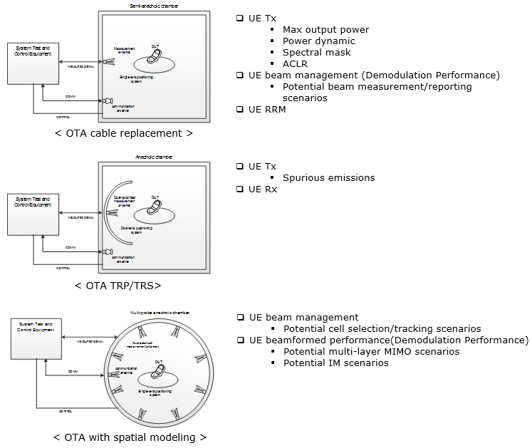
Three OTA configurations proposed in R4-165050. The chamber, the measurement antenna and the positioner change from panel to panel. Those three choices decide which test items each configuration can carry.
- < OTA cable replacement > uses a Semi-anechoic chamber. The measurement antenna is a single horn on the chamber wall, and the DUT sits on a Single-axis positioning system. The title says what the setup is for. It replaces the RF cable, and its hardware is the simplest of the three.
- < OTA TRP/TRS > uses a fully Anechoic chamber. The measurement antenna is Dual-polarized and is mounted on an arch, and the DUT sits on a Dual-axis positioning system. TRP and TRS are integrals over the whole sphere. The setup therefore has to sample every direction in both polarizations, and the arch plus the two positioner axes are how it reaches them.
- < OTA with spatial modeling > uses a Multi-probe anechoic chamber. Dual-polarized measurement antennas are spaced around the wall in a ring, and the DUT sits on a Single-axis positioning system again. The probes radiate together rather than one at a time. So the DUT sees an angular spread of power, rather than a single plane wave arriving from one direction.
- The communication antenna is separate from the measurement antenna in all three panels. That split matters. It lets the equipment hold the call on one antenna while the other one measures. It also keeps the connection itself out of the measured result.
Which test items go to which configuration ?
The three setups are not alternatives that you pick by preference. Each one buys a different measurement capability, and each one costs a different amount of chamber and positioner. So the right question is not which setup is best. It is which setup a given test item actually needs.
Let me take the assignments in the order the drawing gives them.
The cable replacement setup takes most of the Tx items : Max output power, Power dynamic, Spectral mask and ACLR. It also takes UE RRM, and UE beam management listed under Demodulation Performance, with potential beam measurement and reporting scenarios beneath it. Each of these can be measured from one direction at a time, so a single horn and a single positioner axis are enough.The TRP/TRS setup takes only two entries, and both need the whole sphere : Spurious emissions under UE Tx, and UE Rx. Spurious emissions can leave the device in any direction, so a measurement from one angle would miss them. UE Rx becomes TRS, which is sensitivity summed over the sphere. Both explain why this is the panel with the Dual-axis positioning system.The chamber grade changes for TRP/TRS as well : the panel is labelled Anechoic chamber rather than Semi-anechoic chamber. That fits a measurement made at very low level across a wide frequency range, where a reflected path would corrupt the result.The spatial modeling setup takes the scenario level items : UE beam management with potential cell selection and tracking scenarios, and UE beamformed performance with potential multi-layer MIMO and potential IM scenarios. None of these can be produced by a single probe. Cell selection needs more than one direction to choose between, and a multi-layer MIMO scenario needs several paths arriving at once.Beam management appears in two panels, and that is not a duplication : the cable replacement panel qualifies it as Demodulation Performance, while the spatial modeling panel pairs it with cell selection and tracking. So the same feature is split by what the measurement has to reproduce, rather than by the name of the feature.
So the proposal is not one OTA method. It is three, chosen per test item, and a lab that wants full coverage has to plan for more than one chamber. That is the practical consequence of the split, and it is the part worth checking against your own test plan.
Reference :
[1] 3GPP RAN4 #80 R4-165050 : Testability considerations for NR