The concept and functionality of NR Timing Advance is same as the LTE Timing Advance. So I suggest you to read LTE Timing Advance as well if you are not familiar with the concept.
Once the Timing Advance(TA) value is received by UE, the UE should apply the value for UL transmission 6 slot after the reception. That is, if TA is received at slot n, the value is applied from slot n+6 as stated in 38.213-4.2.
The reason the uplink needs any advance at all comes from geometry. UEs sit at different distances from the gNB, so their transmissions take different times to arrive. If every UE started its uplink frame when it saw the downlink frame begin, the far ones would arrive late. The uplink would stop being orthogonal at the receiver.
Timing advance removes that spread. Each UE starts its uplink frame early, by roughly the round trip time to the gNB. A UE 3 km away transmits about 20 microseconds ahead of the downlink it sees. A UE at the cell edge starts earlier still, and both arrive at the gNB together.
I find it easier to think of timing advance as a distance measurement expressed in time. The UE never calculates the value itself. It has no way to measure its own distance, so the gNB measures the arrival time and sends back a correction. Every mechanism on this page therefore runs from the network towards the UE.
The sections that follow cover how the value reaches the UE, and how the integer inside the message becomes a time. They also cover why the first value and later values are read differently, and what happens when alignment is lost.
- UL/DL Timing Relations
- How TimingAdvance information is delivered to UE ?
- How is the timing advance value actually calculated ?
- Why is the RAR value absolute and the MAC CE value relative ?
- What is a Timing Advance Group for ?
- What happens when timeAlignmentTimer expires ?
- Reference
UL/DL Timing Relations
Simply put, Timing Advance is a special command (notification) from gNB to UE that enable UE to adjust its uplink transmission. This kind of UL adjustment applies to PUSCH, PUCCH and SRS.
38.211 Figure 4.3.1-1 draws the relation as two frames on one timeline. The downlink frame is what the UE receives. The uplink frame is what the UE transmits, and it sits earlier by a fixed amount. The arrow between the two frame starts marks that amount, and it is (N_TA + N_TA_offset) x Tc.
Two separate quantities are added there, and they come from different places. N_TA is the UE specific part. The gNB measures it and signals it to this UE alone. N_TA_offset is a constant for the cell, and every UE in that cell applies the same value.
< 38.211 - Figure 4.3.1-1: Uplink-downlink timing relation >

Tc is marked in the figure as 0.509 ns. It is the shortest time unit NR defines, and every timing advance value is counted in multiples of it.
The lower half of the figure gives the two expressions that produce N_TA. The RAR form sets it, and the MAC CE form adjusts what is already there. T_A spans 0 to 3846 in the RAR and only 0 to 63 in the MAC CE. Why the RAR value is absolute and the MAC CE value relative works that difference through.
That two term form is the Release 15 one, and it is the one the figure carries. Clause 4.3.1 has since grown two more terms. The current text gives the advance as (N_TA + N_TA_offset + N_TA_adj_common + N_TA_adj_UE) x Tc.
Both new terms are there for non terrestrial and air to ground links. N_TA_adj_common comes from the network, through ta-Common, ta-CommonDrift and ta-CommonDriftVariant. N_TA_adj_UE is different. The UE computes that one itself, from its own position together with the serving satellite ephemeris, or with the gNB location in atg-gNB-Location.
That difference is worth noticing. Everywhere else on this page the network measures and the UE applies what it is told. A satellite link is the exception, because the delay is large and keeps changing even when the UE is not moving. So the UE is given what it needs to compute part of its own advance.
On a terrestrial cell both new terms are zero, and clause 4.3.1 says so for each of them. So the two term form still describes ordinary NR, and the rest of this page holds unchanged. One smaller change arrived with 2 step RACH. N_TA is 0 for a msgA transmission on PUSCH.
What is N_TA_offset and why is it there ?
N_TA can reach zero. A UE sitting directly under the antenna needs no advance for propagation. If the total advance were N_TA alone, that UE would transmit its uplink frame at the same instant it receives the downlink frame.
That is a problem in TDD, where one carrier carries both directions. The radio has to switch from receiving to transmitting, and switching is not instant. N_TA_offset buys that time. It shifts the whole uplink earlier for every UE in the cell, whatever the distance.
Coexistence is the second reason. When an NR carrier shares a band with LTE, the NR uplink has to line up with the LTE uplink. The offset is what lines them up. That is why the table splits on whether LTE-NR coexistence applies.
< 38.133 - Table 7.1.2-2 : N_TA_offset >
|
Frequency range and band of cell used for uplink transmission |
N_TA_offset (unit : Tc) |
Same offset in time |
|---|---|---|
|
FR1 FDD band without LTE-NR coexistence case, or |
25600 |
13.02 us |
|
FR1 FDD band with LTE-NR coexistence case |
0 |
0 |
|
FR1 TDD band with LTE-NR coexistence case |
39936 |
20.31 us |
|
FR2 |
13792 |
7.01 us |
Two details in that table are worth keeping. FR2 uses a far smaller offset, because its symbols are much shorter and less absolute time covers the same switching gap. And the value is a constant per cell, so it never appears in a MAC CE.
ServingCellConfigCommon below carries the field that selects the offset. n-TimingAdvanceOffset is the only part of this large structure that matters here, and it is marked OPTIONAL. When it is absent, the UE assumes 25600 on an FR1 band.
The enum offers n0, n25600 and n39936, which is three of the four rows above. The FR2 value of 13792 is never signalled, because FR2 has only one value and the UE already knows it. The same offset has to be given for every uplink carrier in one Timing Advance Group. What is a Timing Advance Group for ? explains why that matters.
The advance has two parts on a terrestrial cell : N_TA is per UE and measured, N_TA_offset is per cell and configured.A non terrestrial link adds two more : N_TA_adj_common arrives in ta-Common and its drift parameters, and the UE computes N_TA_adj_UE from satellite ephemeris or from atg-gNB-Location.The offset is not about distance : It buys the TDD switching time and aligns NR uplink with LTE uplink.FR2 is not signalled : Its offset is fixed at 13792, so the enum covers the FR1 cases only.
Following is based on
ServingCellConfigCommon ::=         SEQUENCE {
    physCellId                          PhysCellId                                                          OPTIONAL,   -- Cond HOAndServCellAdd,
    downlinkConfigCommon                DownlinkConfigCommon                                                OPTIONAL,   -- Cond HOAndServCellAdd
    uplinkConfigCommon                  UplinkConfigCommon                                                  OPTIONAL,   -- Need M
    supplementaryUplinkConfig           UplinkConfigCommon                                                  OPTIONAL,   -- Need S
    n-TimingAdvanceOffset               ENUMERATED { n0, n25600, n39936 }                                   OPTIONAL,   -- Need S
    ssb-PositionsInBurst                CHOICE {
        shortBitmap                         BIT STRING (SIZE (4)),
        mediumBitmap                        BIT STRING (SIZE (8)),
        longBitmap                          BIT STRING (SIZE (64))
    }                                                                                                       OPTIONAL,   -- Cond AbsFreqSSB
    ssb-periodicityServingCell          ENUMERATED { ms5, ms10, ms20, ms40, ms80, ms160, spare2, spare1 }   OPTIONAL,   -- Need S
    dmrs-TypeA-Position                 ENUMERATED {pos2, pos3},
    lte-CRS-ToMatchAround               SetupRelease { RateMatchPatternLTE-CRS }                            OPTIONAL,   -- Need M
    rateMatchPatternToAddModList        SEQUENCE (SIZE (1..maxNrofRateMatchPatterns)) OF RateMatchPattern   OPTIONAL,   -- Need N
    rateMatchPatternToReleaseList       SEQUENCE (SIZE (1..maxNrofRateMatchPatterns)) OF RateMatchPatternId OPTIONAL,   -- Need N
    ssbSubcarrierSpacing                SubcarrierSpacing                                                   OPTIONAL,   -- Cond HOAndServCellWithSSB
    tdd-UL-DL-ConfigurationCommon       TDD-UL-DL-ConfigCommon                                              OPTIONAL,   -- Cond TDD
    ss-PBCH-BlockPower                  INTEGER (-60..50),
    ...,
    [[
    channelAccessMode-r16               CHOICE {
        dynamic                             NULL,
        semiStatic                          SemiStaticChannelAccessConfig-r16
    }                                                                                                       OPTIONAL,   -- Cond SharedSpectrum
    discoveryBurstWindowLength-r16      ENUMERATED {ms0dot5, ms1, ms2, ms3, ms4, ms5}                       OPTIONAL,   -- Need R
    ssb-PositionQCL-r16                 SSB-PositionQCL-Relation-r16                                        OPTIONAL,   -- Cond SharedSpectrum
    highSpeedConfig-r16                 HighSpeedConfig-r16                                                 OPTIONAL    -- Need R
    ]],
    [[
    highSpeedConfig-v1700               HighSpeedConfig-v1700                                               OPTIONAL,   -- Need R
    channelAccessMode2-r17              ENUMERATED {enabled}                                                OPTIONAL,   -- Cond SharedSpectrum2
    discoveryBurstWindowLength-r17      ENUMERATED {ms0dot125, ms0dot25, ms0dot5, ms0dot75, ms1, ms1dot25}  OPTIONAL,   -- Need R
    ssb-PositionQCL-r17                 SSB-PositionQCL-Relation-r17                                        OPTIONAL,   -- Cond SharedSpectrum2
    highSpeedConfigFR2-r17              HighSpeedConfigFR2-r17                                              OPTIONAL,   -- Need R
    uplinkConfigCommon-v1700            UplinkConfigCommon-v1700                                            OPTIONAL,   -- Need R
    ntn-Config-r17                      NTN-Config-r17                                                      OPTIONAL    -- Need R
    ]],
    [[
    featurePriorities-r17               SEQUENCE {
        redCapPriority-r17                  FeaturePriority-r17                                             OPTIONAL,   -- Need R
        slicingPriority-r17                 FeaturePriority-r17                                             OPTIONAL,   -- Need R
        msg3-Repetitions-Priority-r17       FeaturePriority-r17                                             OPTIONAL,   -- Need R
        sdt-Priority-r17                    FeaturePriority-r17                                             OPTIONAL    -- Need R
    }                                                                                                       OPTIONAL    -- Need R
    ]],
    [[
    ra-ChannelAccess-r17                ENUMERATED {enabled}                                                OPTIONAL    -- Cond SharedSpectrum2
    ]],
    [[
    featurePriorities-v1800             SEQUENCE {
        msg1-Repetitions-Priority-r18       FeaturePriority-r17                                             OPTIONAL,   -- Need R
        eRedCapPriority-r18                 FeaturePriority-r17                                             OPTIONAL    -- Need R
    }                                                                                                       OPTIONAL,   -- Need R
    atg-Config-r18                      ATG-Config-r18                                                      OPTIONAL    -- Need R
    ]]
}
Everything after the ... marker in that listing arrived in a later release, and one entry there touches this page. The field ntn-Config-r17 configures the non terrestrial parameters of the cell. A non terrestrial cell is exactly where the timing advance range described here stops being sufficient. The other groups cover shared spectrum, high speed scenarios, feature priorities and atg-Config-r18.
How TimingAdvance information is delivered to UE ?
A timing advance has to reach the UE at two moments that have almost nothing in common. One message cannot serve both. So NR uses two different carriers, and the choice between them is not a matter of preference. It depends only on whether the UE already holds an alignment worth correcting.
The first moment comes before any uplink alignment exists. A MAC CE cannot be used there. A MAC CE travels in a scheduled transport block, and scheduling an uplink transmission is exactly what the missing alignment prevents. Something outside the normal flow has to carry the first value, and that is the Random Access Response.
The second moment is easier. A connection is running, the UE is already close to aligned, and a small correction is all that is needed. A MAC CE fits that, and it is what the network uses from then on. The two cases that follow are in that order.
Case 1 : Through RAR
UE figures out the timing advance value from two different MAC layer command depending on situation. For the first Uplink message after PRACH, UE applies the Timing Advance value that it extracts from RAR (RACH Response). After the initial RACH process, UE would apply the timing Advance value that it extract from Timing Advance MAC CE if it received it.
The RAR MAC PDU is drawn one octet per row, and three of its fields are expanded into the tables that define them. Read the left column downwards. The first two rows are MAC subheaders, one carrying BI and one carrying RAPID. The MAC RAR itself starts on the third row, and Timing Advance is the first field in it. It spans two octets, seven bits in the first and five in the second. UL Grant follows over the next rows, and Temporary C-RNTI closes the payload.
< 38.321 - 6.2.2, 6.2.3 : Random Access Response MAC PDU >
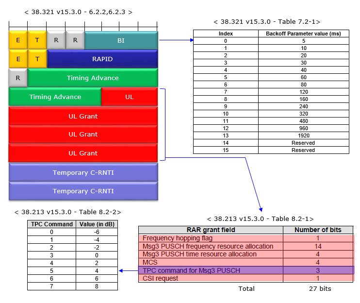
- Timing Advance is 12 bits, which is where the range of 0 to 3846 steps comes from. The field sits at the very front of the MAC RAR, ahead of the grant the UE needs in order to answer.
- UL Grant is 27 bits, and 38.213 Table 8.2-1 splits it into six fields. Msg3 PUSCH frequency resource allocation takes 14 of those 27, and the other five fields share the remaining 13.
- BI in the first subheader maps to a backoff time through 38.321 Table 7.2-1. Index 0 is 5 ms and index 13 is 1920 ms, with 14 and 15 reserved. This is how long a UE waits before it retries a preamble.
- TPC command for Msg3 PUSCH is 3 bits, and 38.213 Table 8.2-2 turns those into -6 to +8 dB in 2 dB steps. So the RAR corrects power and timing in the same message.
Case 2 : Through MAC CE
As mentioned above, UE adjust UL transmission timing based on RAR during the initial attach. Once the initial attach is complete, UE adjust UL transmission based on the MAC CE-Timing Advance. The structure of MAC CE Timing Advance is shown in 38.321 Figure 6.1.3.4-1.
< 38.321 - Figure 6.1.3.4-1: Timing Advance Command MAC CE >
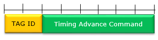
You see here the Timing Advance Command Field is 6 bits which mean 64 steps in total. One step is 16 x 64 x Tc divided by 2 raised to the numerology, and Tc is about 0.509 ns. One step is therefore about 521 ns at 15 kHz. The adjustment runs from -31 to +32 steps, or about -16.1 us to +16.7 us at 15 kHz. It halves with every step up in subcarrier spacing. How is the timing advance value actually calculated works this through.
The TAG field in the MAC CE refers to the tag-Id specified in the TAG-Config below.
Following is based on
MAC-CellGroupConfig ::=             SEQUENCE {
    drx-Config                          SetupRelease { DRX-Config }                                     OPTIONAL,   -- Need M
    schedulingRequestConfig             SchedulingRequestConfig                                         OPTIONAL,   -- Need M
    bsr-Config                          BSR-Config                                                      OPTIONAL,   -- Need M
    tag-Config                          TAG-Config                                                      OPTIONAL,   -- Need M
    phr-Config                          SetupRelease { PHR-Config }                                     OPTIONAL,   -- Need M
    skipUplinkTxDynamic                 BOOLEAN,
    ...,
    [[
    csi-Mask                            BOOLEAN                                                         OPTIONAL,   -- Need M
    dataInactivityTimer                 SetupRelease { DataInactivityTimer }                            OPTIONAL    -- Cond MCG-Only
    ]],
    -- ... two Release 16 extension groups omitted here, none of them timing advance related
    [[
    intraCG-Prioritization-r17          ENUMERATED {enabled}                                            OPTIONAL,   -- Cond LCH-PrioWithReTxTimer
    drx-ConfigSL-r17                    SetupRelease { DRX-ConfigSL-r17 }                               OPTIONAL,   -- Need M
    drx-ConfigExt-v1700                 SetupRelease { DRX-ConfigExt-v1700 }                            OPTIONAL,   -- Need M
    schedulingRequestID-BFR-r17         SchedulingRequestId                                             OPTIONAL,   -- Need R
    schedulingRequestID-BFR2-r17        SchedulingRequestId                                             OPTIONAL,   -- Need R
    schedulingRequestConfig-v1700       SchedulingRequestConfig-v1700                                   OPTIONAL,   -- Need M
    tar-Config-r17                      SetupRelease { TAR-Config-r17 }                                 OPTIONAL,   -- Need M
    -- ... the five MBS g-RNTI fields of this group are omitted here
    ]],
    -- ... two further Release 17 extension groups omitted here, neither timing advance related
    [[
    drx-ConfigExt2-v1800                SetupRelease { DRX-ConfigExt2-v1800 }                           OPTIONAL,   -- Need M
    additionalBS-TableAllowed-r18       BIT STRING (SIZE (maxNrofLCGs-r18))                             OPTIONAL,   -- Need R
    dsr-ConfigToAddModList-r18          SEQUENCE (SIZE (1..maxNrofLCGs-r18)) OF LCG-DSR-Config-r18      OPTIONAL,   -- Need N
    dsr-ConfigToReleaseList-r18         SEQUENCE (SIZE (1..maxNrofLCGs-r18)) OF LCG-Id-r18              OPTIONAL,   -- Need N
    tar-Config-r18                      SetupRelease { TAR-Config-r18 }                                 OPTIONAL    -- Need M
    ]],
    -- ... the Release 19 extension group is omitted here, none of it timing advance related
}

TAG-Config ::=                      SEQUENCE {
    tag-ToReleaseList                   SEQUENCE (SIZE (1..maxNrofTAGs)) OF TAG-Id                      OPTIONAL,   -- Need N
    tag-ToAddModList                    SEQUENCE (SIZE (1..maxNrofTAGs)) OF TAG                         OPTIONAL    -- Need N
}

TAG ::=                             SEQUENCE {
    tag-Id                              TAG-Id,
    timeAlignmentTimer                  TimeAlignmentTimer,
    ...
}

TAG-Id ::=                          INTEGER (0..maxNrofTAGs-1)   // maxNrofTAGs = 4

TimeAlignmentTimer ::=              ENUMERATED {ms500, ms750, ms1280, ms1920, ms2560, ms5120, ms10240, infinity}
Following is based on
TAR-Config-r17 ::=                  SEQUENCE {
    offsetThresholdTA-r17               ENUMERATED {ms0dot5, ms1, ms2, ms3, ms4, ms5, ms6 ,ms7, ms8, ms9, ms10, ms11, ms12,
                                                   ms13, ms14, ms15, spare13, spare12, spare11, spare10, spare9, spare8, spare7,
                                                   spare6, spare5, spare4, spare3, spare2, spare1}          OPTIONAL,   -- Need R
    timingAdvanceSR-r17                 ENUMERATED {enabled}                                                OPTIONAL,   -- Need R
    ...
}

TAR-Config-r18 ::=                  SEQUENCE {
    offsetThresholdTA-r18               INTEGER (1..56)                                                     OPTIONAL,   -- Need R
    timingAdvanceSR-r18                 ENUMERATED {enabled}                                                OPTIONAL,   -- Need R
    ...
}
Two fields in MAC-CellGroupConfig were not there when this page was first written, and both belong to this topic. Those two, tar-Config-r17 and tar-Config-r18, configure timing advance reporting, and each carries the same two settings. The field offsetThresholdTA sets how far the timing advance has to move before a report is due. Then timingAdvanceSR lets the UE raise a scheduling request to send one.
The direction is what makes these worth noticing. Everywhere else on this page the gNB measures and the UE obeys. Here the UE watches its own value and speaks first. Both fields arrived in Release 17 alongside ntn-Config-r17, and Case 1 : Through RAR already flags NTN as the case a 12 bit RAR value cannot cover.
How is the timing advance value actually calculated ?
Both carriers of a timing advance send an integer, and neither sends a time. Turning that integer into a time takes one constant and one multiplier. The multiplier is the part that is easy to miss.
The constant is Tc, the basic time unit of NR. It is defined as 1 divided by 480000 times 4096, which is about 0.509 nanoseconds. Note the unit. Tc is measured in nanoseconds, not microseconds.
The multiplier is 16 times 64, divided by 2 raised to the numerology. One step of timing advance is therefore 16 x 64 x Tc / 2^u, which is about 521 nanoseconds at 15 kHz. A step is not one Tc. It is 1024 of them at the lowest numerology.
That division by 2^u is what ties timing advance to the subcarrier spacing. Every step up in subcarrier spacing halves the step size, and halves the total range with it.
|
mu |
Subcarrier spacing |
One step |
MAC CE adjustment range |
Largest RAR value |
Cell radius that covers |
|---|---|---|---|---|---|
|
|
15 kHz |
521 ns |
-16.1 to +16.7 us |
2.00 ms |
300 km |
|
|
30 kHz |
260 ns |
-8.1 to +8.3 us |
1.00 ms |
150 km |
|
|
60 kHz |
130 ns |
-4.0 to +4.2 us |
0.50 ms |
75 km |
|
|
120 kHz |
65 ns |
-2.0 to +2.1 us |
0.25 ms |
38 km |
The last column is the useful one for planning. The largest value a RAR can carry corresponds to a round trip. The distance it covers is half of that, at the speed of light. About 300 km at 15 kHz is the well known figure for the maximum NR cell radius. It comes from this table, rather than from anything about the radio.
The MAC CE column tells a different story. At 15 kHz a single command moves the transmit time by at most about 16.7 microseconds. That is a change of about 2.5 km in distance. A UE that moves further than that between commands needs more than one command.
Tc is nanoseconds, not microseconds : About 0.509 ns, defined as 1 over 480000 times 4096.One step is 16 x 64 x Tc / 2^u : About 521 ns at 15 kHz, not one Tc.Range halves with every numerology step : The same integer means half the time at twice the subcarrier spacing.The RAR range sets the cell radius : About 300 km at 15 kHz, and about 150 km at 30 kHz.One MAC CE moves about 2.5 km at 15 kHz : A larger correction needs more than one command.
Why is the RAR value absolute and the MAC CE value relative ?
The page above says the first timing advance comes from the RAR, and every later one from a MAC CE. The two are read in completely different ways, and the difference is not just the field width.
The RAR value is absolute. The UE has just sent a preamble and holds no timing advance at all, so there is nothing to adjust. The 12 bits are read as a value from 0 to 3846, and N_TA is simply that number times the step. It can only be positive, because a UE cannot transmit later than the reference.
The MAC CE value is relative. By the time it arrives the UE already has a roughly correct timing advance. What the network wants is a correction. The 6 bits are read as a value from 0 to 63. Then 31 is subtracted before the step is applied. That gives a signed offset from -31 to +32, which is added to the value the UE already holds.
The offset of 31 is what allows a command that changes nothing. A T_A of exactly 31 subtracts nothing and leaves the timing where it is. That is useful when the network wants to restart the alignment timer without moving the UE.
Figure 1. The two carriers answer different questions. One asks where the UE is, and the other asks how far it has drifted.
The RAR value replaces : The UE holds nothing at that point, so the 12 bits give the whole value.The MAC CE value adjusts : Its 6 bits are a signed offset added to what the UE already has.Subtracting 31 makes the offset signed : It runs from -31 to +32 rather than 0 to 63.A T_A of 31 changes nothing : The command still restarts timeAlignmentTimer, which is sometimes the only reason it was sent.The RAR value is never negative : A UE transmits earlier than the reference, never later.
What is a Timing Advance Group for ?
The ASN.1 above shows TAG-Config, tag-Id and a maximum of four groups. It does not say why more than one would be needed. On a single carrier one is plenty.
Carrier aggregation is what changes that. A UE can be served by several cells at once, and those cells are not always at the same place. A macro cell and a small cell serving one UE can sit hundreds of metres apart. The propagation delay to each is then different. One timing advance cannot be right for both.
A Timing Advance Group is a set of serving cells that share one timing advance. Cells at the same site go in the same group. Cells far enough apart to need different alignment go in different groups. Each group is corrected by its own MAC CE.
The group holding the primary cell is the primary TAG, and the others are secondary TAGs. That distinction matters when the alignment timer expires, because the consequences differ between them.
This is also what the TAG field in the MAC CE is for. Two bits address the four groups, and the field says which group the correction applies to. Without carrier aggregation the field is always 0.
One group is one timing advance : Every serving cell in a group shares the same uplink alignment.Groups exist because sites differ : Cells at different locations have different propagation delays and cannot share a value.Up to four groups : maxNrofTAGs is 4, which is why the TAG field needs only two bits.The primary group is special : It holds the primary cell. Losing its alignment costs more than losing a secondary group's.Without carrier aggregation the field is 0 : A single serving cell needs only one group.
What happens when timeAlignmentTimer expires ?
The ASN.1 above gives timeAlignmentTimer its values, from 500 milliseconds to infinity, without saying what the timer is guarding. It is worth knowing, because expiry is expensive.
Every timing advance command restarts the timer for its group. While the timer runs the UE considers its uplink aligned for that group, and it may transmit. The timer is what makes a timing advance perishable. A UE that hears nothing for long enough has to assume its alignment has drifted out of usefulness.
Expiry for a secondary group is the milder case. The UE stops transmitting on the cells in that group. The rest of the connection continues, because the primary group is still aligned.
Expiry for the primary group is the serious one. The UE treats its whole uplink as unaligned. It flushes the HARQ buffers and releases the PUCCH and SRS configurations. It clears any configured assignments and grants, and stops transmitting. Getting back means random access, which is where the RAR at the top of this page comes in again.
Setting the timer to infinity is allowed and is occasionally right. A fixed wireless terminal does not move, so its alignment does not drift. There is no reason to make it repeat random access. A moving UE with a long timer keeps transmitting on a stale value. That interferes with everyone else in the cell.
Every command restarts the timer : Even a T_A of 31, which changes nothing, keeps the group alive.Secondary group expiry is local : Transmission stops on that group, and the rest of the connection continues.Primary group expiry ends the uplink : HARQ buffers flushed, PUCCH and SRS released, grants cleared.Recovery is random access : The UE goes back to a preamble and a RAR to get a fresh absolute value.Infinity suits a UE that does not move : For anything mobile it means transmitting on a stale alignment.
Reference
[1] 3GPP TS 38.213 - NR; Physical layer procedures for control. Section 4.2 defines the timing advance formulas and when an adjustment applies.
[2] 3GPP TS 38.211 - NR; Physical channels and modulation. Section 4.1 defines Tc, the basic time unit, and section 4.3.1 gives the uplink to downlink timing relation.
[3] 3GPP TS 38.321 - NR; Medium Access Control (MAC) protocol specification. Section 6.1.3.4 defines the Timing Advance Command MAC CE, and section 5.2 covers the maintenance of uplink time alignment.
[4] 3GPP TS 38.331 - NR; Radio Resource Control (RRC) protocol specification. TAG-Config, TAG-Id and TimeAlignmentTimer are defined here.