PUCCH is an uplink physical channel that carries UCI (Uplink Control Information). As DCI (Downlink Control Information) is carried by PDCCH, UCI is carried by PUCCH. A big difference between DCI and UCI is that UCI can be carried either by PUCCH or PUSCH depending on situation whereas DCI can be carried only by PDCCH (not by PDSCH in any case).
Contents of UCI
The contents of UCI is as follows (this is same as LTE). Not all of these are carried by single UCI. Depending on situation, sometimes only CSI is carried, sometimes ACK/NACK only, sometimes SR only and sometimes CSI & ACK/NACK etc.
- ACK/NAK
- Scheduling Request (SR)
- CSI
These three elements are combined in various way and reported to a Network via uplink physical channel : PUCCH or PUSCH. The possible combinations of these elements can be listed as below. (NOTE : Most of these UCI can be carried by either PUCCH or PUSCH, but UCI with SR can be carried by PUCCH only based on 38.212 - 6.3.1.1 and 6.3.2.1)
i) HARQ ACK/NACK only
ii) SR only
iii) HARQ ACK/NACK + SR
iv) CSI only
v) CSI + SR
vi) HARQ ACK/NACK + CSI
vii) HARQ ACK/NACK + SR + CSI
That list is easier to remember once you notice it is not arbitrary. Three elements give seven non-empty combinations, and the specification allows all seven. So there is nothing to memorise here. Any mix of HARQ ACK/NACK, SR and CSI is legal, and the only restriction is the one noted above about SR.
The three elements also differ in what starts them, and that is worth separating early. HARQ ACK/NACK exists because the gNB sent something on the downlink and needs to know whether it arrived. SR exists because the UE has data waiting and no grant to send it with. CSI exists because the network asked for it, either by configuration or by a request in DCI.
That difference in origin also explains the PUSCH restriction. Consider a UE that already holds a PUSCH grant. It has no reason to ask for another one, so SR has no purpose on PUSCH. HARQ ACK/NACK and CSI carry a value rather than a request, and both can be carried on either channel.
The seven combinations are easier to believe once you see how each one arises, so a short sequence for each follows. Throughout these, slot n means the slot in which the UCI is actually transmitted.
Case i : HARQ ACK/NACK only
The simplest of the seven, and the one a connected UE performs constantly. Nothing here is started by the UE. The gNB sends data, the UE reports whether it decoded, and the slot for that report was already named in the grant that scheduled the data.
|
Step |
Direction |
Channel |
What happens |
|
1 |
gNB → UE |
PDCCH |
DCI schedules a PDSCH. Its PDSCH-to-HARQ_feedback timing indicator names the slot for the report, and the PUCCH resource indicator names the resource. |
|
2 |
gNB → UE |
PDSCH |
The transport block arrives. |
|
3 |
UE |
- |
The UE decodes the transport block and checks the CRC. |
|
4 |
UE → gNB |
PUCCH |
One HARQ-ACK bit, ACK or NACK, in the slot the indicator named. |
Case ii : SR only
This is the one case the UE starts by itself. Uplink data has arrived with no grant to carry it, so the UE has to ask for one. Note that only a positive SR is ever transmitted. With nothing to request, the UE simply does not transmit.
|
Step |
Direction |
Channel |
What happens |
|
1 |
gNB → UE |
RRC |
SchedulingRequestResourceConfig gives the UE a periodic SR occasion and a PUCCH resource to use for it. |
|
2 |
UE |
- |
Data arrives in an uplink logical channel and a BSR is triggered. |
|
3 |
UE |
- |
No UL-SCH resources are available for a new transmission, so MAC triggers an SR. The SR stays pending until it is cancelled. |
|
4 |
UE → gNB |
PUCCH |
The UE transmits on the SR resource at the next SR occasion. It carries nothing beyond the fact of the request. |
|
5 |
gNB → UE |
PDCCH |
DCI gives an uplink grant, and the SR is cancelled. |
Case iii : HARQ ACK/NACK + SR
Now two independent things want the same slot. The HARQ-ACK slot was fixed by the downlink grant and the SR occasion is periodic, so the overlap is a matter of timing rather than of choice. The UE drops neither one.
|
Step |
Direction |
Channel |
What happens |
|
1 |
gNB → UE |
PDCCH + PDSCH |
A downlink transmission puts a HARQ-ACK report in slot n. |
|
2 |
UE |
- |
Separately, a BSR triggers an SR, and an SR occasion falls in slot n too. |
|
3 |
UE |
- |
The two PUCCH resources overlap, so the UE multiplexes instead of choosing. |
|
4 |
UE → gNB |
PUCCH |
The SR is carried by the sequence the UE selects, not by an extra bit. This is the case for one or two HARQ-ACK bits on PUCCH format 0, and 38.213 Table 9.2.5-1 and Table 9.2.5-2 give the mapping. |
Case iv : CSI only
Nothing has been received here and nothing is being requested. A periodic CSI report is simply due, because RRC configured it to be. The UE measures a reference signal it was told about well in advance, and reports what it measured.
|
Step |
Direction |
Channel |
What happens |
|
1 |
gNB → UE |
RRC |
CSI-ReportConfig makes the report periodic, names the resource to measure and names the PUCCH resource to report on. |
|
2 |
gNB → UE |
CSI-RS |
The NZP CSI-RS is transmitted on the configured resource. |
|
3 |
UE |
- |
The UE measures it and computes the report, for example CRI, RI, PMI and CQI. |
|
4 |
UE → gNB |
PUCCH |
The CSI report is transmitted in the configured slot. |
Case v : CSI + SR
This is the same overlap as Case iii, with CSI in place of HARQ-ACK. Both events are periodic and are configured independently of each other, so sooner or later their occasions fall in one slot. Again neither is dropped.
|
Step |
Direction |
Channel |
What happens |
|
1 |
gNB → UE |
RRC |
A periodic CSI report and an SR configuration are set up, each with its own periodicity. |
|
2 |
UE |
- |
A CSI report falls due in slot n. |
|
3 |
UE |
- |
A BSR triggers an SR, and an SR occasion falls in slot n as well. |
|
4 |
UE → gNB |
PUCCH |
Both are carried on one PUCCH. The payload is larger than two bits, so this needs one of the PUCCH formats that carry more than a couple of bits. |
Case vi : HARQ ACK/NACK + CSI
Here the two events have different origins. The gNB chose the HARQ-ACK slot when it scheduled the PDSCH, and RRC fixed the CSI slot long before that. Neither decision took account of the other.
|
Step |
Direction |
Channel |
What happens |
|
1 |
gNB → UE |
RRC |
A periodic CSI report is configured in a way that puts a report in slot n. |
|
2 |
gNB → UE |
PDCCH + PDSCH |
A downlink transmission puts a HARQ-ACK report in slot n as well. |
|
3 |
UE |
- |
The two PUCCH resources overlap in that slot. |
|
4 |
UE → gNB |
PUCCH |
HARQ-ACK and CSI are multiplexed onto one PUCCH resource. |
Case vii : HARQ ACK/NACK + SR + CSI
All three at once, which is rarer but perfectly legal. It takes a downlink transmission, a CSI report that is due and a triggered SR to converge on one slot. The mechanism is no different from the two-way cases, and only the payload is bigger.
|
Step |
Direction |
Channel |
What happens |
|
1 |
gNB → UE |
PDCCH + PDSCH |
A downlink transmission puts a HARQ-ACK report in slot n. |
|
2 |
gNB → UE |
CSI-RS |
A configured CSI report also falls due in slot n. |
|
3 |
UE |
- |
A BSR triggers an SR, and an SR occasion falls in slot n. |
|
4 |
UE |
- |
Three PUCCH resources now overlap in the same slot. |
|
5 |
UE → gNB |
PUCCH |
All three are multiplexed onto one PUCCH. This is the largest UCI payload of the seven cases. |
Take the seven together and the pattern is easy to state. Only three of them are a single event, and those are Case i, Case ii and Case iv. The other four are overlaps, and every overlap is resolved the same way, because the UE multiplexes rather than chooses. So the seven combinations are not seven separate designs. They are three independent events that sometimes fall in the same slot.
Seven combinations, and that is all of them : three elements give seven non-empty subsets, so the list is complete rather than selective.Each element has a different trigger : a downlink transmission starts HARQ ACK/NACK, buffered data starts SR, and the network starts CSI.SR is the only one tied to PUCCH : 38.212 6.3.1.1 and 6.3.2.1 keep any UCI containing SR off PUSCH.The combination decides the payload : how many bits the UCI carries is what the PUCCH format then has to accommodate.
Bit Structure of UCI
Bit structure of UCI would be simple and obvious when it carries HARQ ACK/NACK and SR, but CSI bit structure of CSI is so complicated and would take a long time / effort to get the detailed understanding. All the details of UCI bit structure is specified in 38.212-6.3.
Bit Structure for HARQ ACK/NACK
Overall bit structure for this case would be relatively straightforward. When CBG is not configured, one bit is allocated for one codeword per carrier. When CBG is configured, one bit is allocated for one CB per carrier. The structure gets a little complicated when multiple report are multiplexed according to TDD structure, but overall the structure would not get as complicated as CSI bit structure case.
The real question in this block is how many bits, and the answer is not one per PDSCH. It comes from the HARQ-ACK codebook, which is the rule that decides how many bits the report carries and what each of them stands for. 38.213 clause 9.1 is where that rule lives, and RRC picks which version of it applies.
The choice is a single mandatory field in PhysicalCellGroupConfig : pdsch-HARQ-ACK-Codebook, an ENUMERATED { semiStatic, dynamic }. Those two values select the two determinations that follow it in the specification, 38.213 clause 9.1.2 for the Type-1 codebook and clause 9.1.3 for the Type-2 codebook.
The Type-1 codebook is the semi-static one, and its size is decided by configuration alone. The UE counts every PDSCH occasion the configuration could have used in the slots the report covers, and reserves a bit for each, whether or not anything was actually scheduled there. Unscheduled positions are simply reported as NACK. This is the mechanism behind multiplexing several reports across the slots that the TDD configuration makes available. The payload is predictable, and it is also larger than it needs to be.
The Type-2 codebook is the dynamic one, and its size follows what was really scheduled. The hard part is agreement. The UE has to arrive at the same bit count as the gNB, even after missing a PDCCH. This is what the DAI (Downlink Assignment Index) in the DCI is for. A counter DAI numbers the transmissions as they go out and a total DAI says how many there are, so a UE still knows a bit belongs there, even after missing one.
Two more settings move the count. When CBG is configured the codebook is built per code block group instead of per transport block, which 38.213 gives its own clause, 9.1.1. And harq-ACK-SpatialBundlingPUCCH or harq-ACK-SpatialBundlingPUSCH, each an ENUMERATED { true }, combines the bits of the two transport blocks of one PDSCH into one, which halves that part of the payload.
Release 16 added to the choice rather than replacing it. The field pdsch-HARQ-ACK-Codebook-r16 is an ENUMERATED { enhancedDynamic }. Alongside it, PDSCH-HARQ-ACK-CodebookList-r16 is a SEQUENCE (SIZE (1..2)) OF ENUMERATED { semiStatic, dynamic }. That list lets the two priority levels of a UE run different codebooks at the same time.
The codebook decides the bit count : not the number of PDSCHs on its own. 38.213 clause 9.1 holds the rule and RRC selects which version applies.Type-1 is sized by configuration : every candidate occasion gets a bit, scheduled or not, so the payload is predictable and larger than necessary.Type-2 is sized by what was scheduled : and the counter and total DAI in the DCI are how the UE stays in step with the gNB after a missed PDCCH.CBG and spatial bundling both move the count : CBG multiplies it per code block group, and spatial bundling halves the two transport block bits into one.
Bit Structure for SR
SR is the simplest of the three, and the reason is that it carries no information beyond its own presence. The UE is not reporting a value here, it is asking for a grant, so one bit per configured SR is enough.
Nothing much to say about this. It is just that one bit is allocated for each SR.
One bit is the whole answer only while SR travels on its own. Two things are worth adding to that, because both change what you see in a log.
The first is that a UE can hold several SR configurations at once. SchedulingRequestToAddMod gives each one a schedulingRequestId, an sr-ProhibitTimer and an sr-TransMax of ENUMERATED { n4, n8, n16, n32, n64, ... }. That last one caps the number of retries, after which the UE uses random access instead. SchedulingRequestResourceConfig then ties that id to a PUCCH resource and a periodicityAndOffset.
That periodicity is worth a look, because it stretches further than most people expect. The CHOICE runs sym2 and sym6or7, then sl1, which recurs in every slot, and on up to sl640. So an SR occasion can recur twice inside one slot at one end of the range, and once every 640 slots at the other.
The second is that the one bit is not always a bit. When SR shares a PUCCH with one or two HARQ-ACK bits on format 0, no SR bit is added at all, because the UE carries it in the sequence it selects. On the formats that carry an actual bit field, SR does occupy real bits alongside the rest of the UCI.
One bit per SR, when SR is alone : the field says only that a request exists, because a negative SR is never transmitted.A UE can hold several SR configurations : each with its own id, PUCCH resource, prohibit timer and retry limit.SR periodicity reaches below a slot : sym2 and sym6or7 sit at one end of the CHOICE and sl640 at the other.On PUCCH format 0 the SR costs no bits : the sequence selection carries it, which is the mechanism Case iii above walks through.
Bit Structure for CSI
This is the most complicated part. The overall structure varies depending on the type of CSI (e.g, PMI or RI/LI/CQI/CRI or CRI/SSBRI/RSRP) and the detailed structure for each CSI type varies further based on some additional factors.
Before any of the bitwidth tables, there is one structural fact that explains most of the complication. A CSI report is not always one block of bits. It can be sent in two parts, and the split is not cosmetic. The two parts are encoded separately and mapped separately.
The reason is a sizing problem. The gNB has to know how many bits to expect before it can decode anything, and for some report types the length of the report depends on values inside the report itself. The rank decides how many PMI and layer indicator fields follow. For Type II, the number of non-zero wideband amplitude coefficients decides how much payload follows. Neither is known until the report is read.
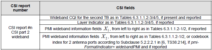
Splitting the report solves it. CSI part 1 has a length the gNB can work out from configuration alone, so it is always decodable. It carries CRI, the rank indicator, wideband CQI for the first transport block and, for Type II, that coefficient count, as 38.212 Table 6.3.1.1.2-9 lists. CSI part 2 then carries everything whose size those values fix, which 38.212 Table 6.3.1.1.2-10 and Table 6.3.1.1.2-11 lay out for the wideband and subband halves.
So the decoding order is forced. The gNB decodes part 1, reads the rank and the coefficient count out of it, computes the length of part 2, and only then decodes part 2. That is also why the two parts get separate mapping tables, 38.212 Table 6.3.1.1.2-13 for part 1 and Table 6.3.1.1.2-14 for part 2.
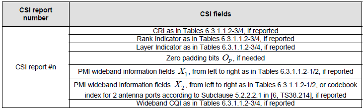
A report with no such dependency stays in one piece. Wideband PMI with wideband CQI has a length that configuration already fixes, so it is a single part, laid out by 38.212 Table 6.3.1.1.2-7 and mapped by Table 6.3.1.1.2-12. The tables in the rest of this section are the widths that feed all of this.
A CSI report may be one part or two : and the two parts are encoded and mapped separately rather than concatenated.Part 1 is always decodable : its length comes from configuration alone, which is what makes the scheme work.Part 1 carries the sizing values : rank, and for Type II the non-zero coefficient count, are what fix the length of part 2.Part 2 cannot be decoded first : the gNB reads part 1, computes the length, and only then decodes part 2.No dependency means no split : wideband PMI with wideband CQI has a length configuration already fixes, so it stays a single part.
|
Codebook Type |
Number of CSI ports |
Rank |
Bitwidth |
|
Type I -Single Pannel |
2 |
1 |
2 |
|
Type I -Single Pannel |
2 |
2 |
1 |
|
Type I -Single Pannel |
> 2 |
|
|
|
Type I -Multi Pannel |
|
|
|
|
|
1 |
|
0 |
UCI on PUCCH - CSI Only
What follows is the lookup material for CSI, taken from 38.212 clause 6.3.1.1.2. It is worth knowing how the run is organised before reading any of it. The tables come in three groups. The first gives the width of each field. The second gives the order of the fields inside one CSI report. The third gives the order of the reports themselves in the UCI bit sequence.
Take them in that order when you are resolving a real report. 38.212 Tables 6.3.1.1.2-1 to 6.3.1.1.2-6 answer how many bits each field takes. Tables 6.3.1.1.2-7 to 6.3.1.1.2-11 answer where each field sits. Tables 6.3.1.1.2-12 to 6.3.1.1.2-14 answer how several reports are concatenated, and they are also where the two-part split becomes visible.
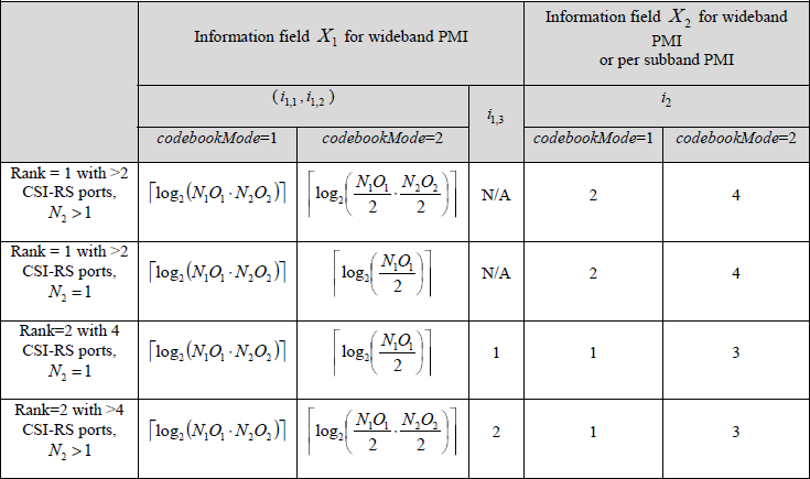
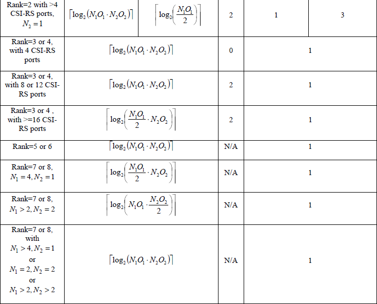
< 38.212-Table 6.3.1.1.2-1: PMI of codebookType=typeI-SinglePanel >
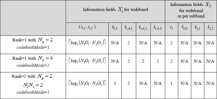
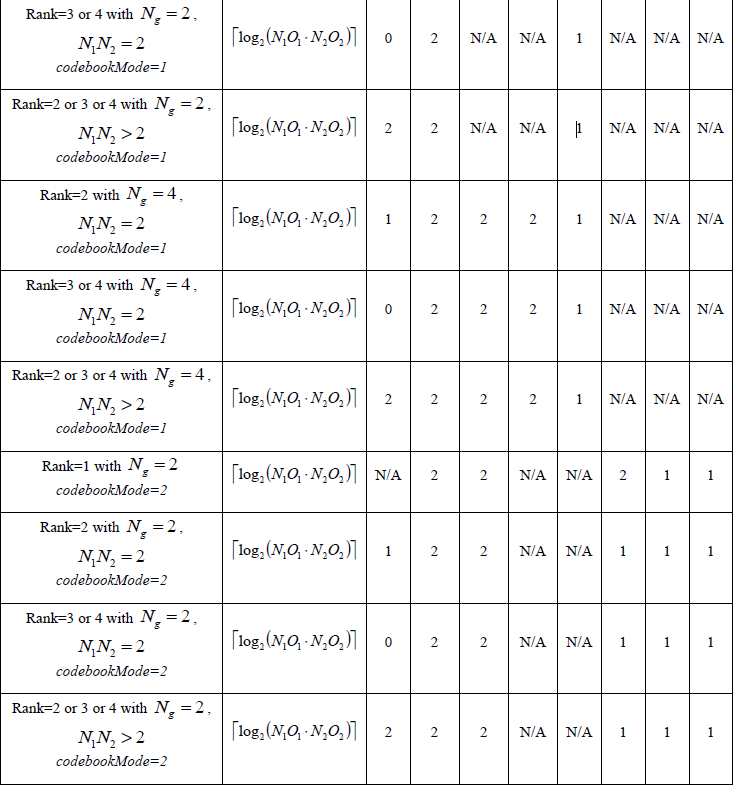
< 38.212-Table 6.3.1.1.2-2: PMI of codebookType= typeI-MultiPanel >
|
Codebook Type |
Bitwidth |
|
Type I -Single Pannel |
|
|
Type I -Single Pannel |
|
|
Type II/Type II Port Selection |
< 38.212-Table 6.3.1.1.2-3: RI, LI, CQI, and CRI of codebookType=typeI-SinglePanel >
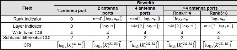
< 38.212-Table 6.3.1.1.2-4: RI, LI, CQI, and CRI of codebookType=typeI-MultiPanel >
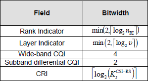
< 38.212-Table 6.3.1.1.2-5: RI, LI, and CQI of codebookType=typeII or typeII-PortSelection >
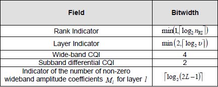
< 38.212-Table 6.3.1.1.2-6: CRI, SSBRI, and RSRP >
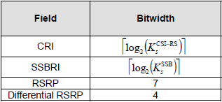
< 38.212-Table 6.3.1.1.2-7: Mapping order of CSI fields of one CSI report, pmi-FormatIndicator=widebandPMI and cqi-FormatIndicator=widebandCQI >
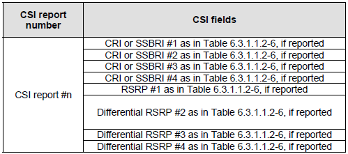
< 38.212-Table 6.3.1.1.2-8: Mapping order of CSI fields of one report for CRI/RSRP or SSBRI/RSRP reporting >
< 38.212-Table 6.3.1.1.2-9: Mapping order of CSI fields of one CSI report, CSI part 1, pmi-FormatIndicator=subbandPMI or cqi-FormatIndicator=subbandCQI >

< 38.212-Table 6.3.1.1.2-10: Mapping order of CSI fields of one CSI report, CSI part 2 wideband, pmi-FormatIndicator= subbandPMI or cqi-FormatIndicator=subbandCQI >
< 38.212-Table 6.3.1.1.2-11: Mapping order of CSI fields of one CSI report, CSI part 2 subband, pmi-FormatIndicator= subbandPMI or cqi-FormatIndicator=subbandCQI >

< 38.212-Table 6.3.1.1.2-12: Mapping order of CSI reports to UCI bit sequence a0 , a1, a2 , a3 ,..., aA−1 , without two part CSI report(s) >

< 38.212-Table 6.3.1.1.2-13: Mapping order of CSI reports to UCI bit sequence with two-part CSI report(s) >
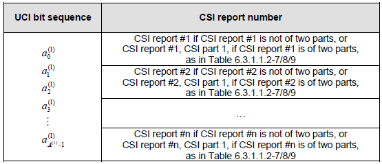
< 38.212-Table 6.3.1.1.2-14: Mapping order of CSI reports to UCI bit sequence with two-part CSI report(s) >
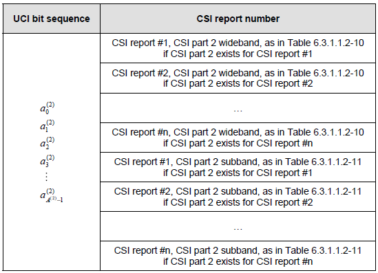
Having gone through them, three comparisons are worth making, because none of them is visible from any single table.
The first is what stays still. Three tables give the same five fields for three codebook types : 38.212 Table 6.3.1.1.2-3 for typeI-SinglePanel, Table 6.3.1.1.2-4 for typeI-MultiPanel and Table 6.3.1.1.2-5 for typeII. What moves between them is the rank indicator and the layer indicator, because both depend on how many ports and layers are in use. What does not move is CQI. Wideband CQI is 4 bits and subband differential CQI is 2 bits in all three.
The second is the one field typeII has and the others do not. 38.212 Table 6.3.1.1.2-5 adds an indicator of the number of non-zero wideband amplitude coefficients, at ceil(log2(2L - 1)) bits. That count decides how much typeII payload follows it. So it has to be read before the rest of the report can be sized. That is why it travels in CSI part 1, and why typeII is the case that forces the two-part split described in Bit Structure of UCI.
The third is the shape of a beam report. 38.212 Table 6.3.1.1.2-8 lists CRI or SSBRI for up to four beams, then RSRP #1, then Differential RSRP #2, #3 and #4. A beam report is therefore not a list of equal entries. The first beam is carried at the full 7 bit resolution of Table 6.3.1.1.2-6 and the rest are carried as 4 bit differences from it. Four beams cost 7 + 3 x 4 = 19 bits that way, rather than the 4 x 7 = 28 bits they would cost at full resolution.
PMI is not one field : 38.212 Table 6.3.1.1.2-1 and Table 6.3.1.1.2-2 split it into X1 and X2. X1 carries the wideband part and X2 the wideband or per subband part, and codebookMode changes both widths.RSRP is reported once in full : 38.212 Table 6.3.1.1.2-6 gives RSRP 7 bits and Differential RSRP 4, which is why Table 6.3.1.1.2-8 lists RSRP #1 and then differential entries.Wideband CQI is 4 bits almost everywhere : 38.212 Table 6.3.1.1.2-3 holds it at 4, and only the column for more than 4 antenna ports at Rank5~8 raises it to 8.Part 2 subband goes even before odd : 38.212 Table 6.3.1.1.2-11 places all even subbands first and all odd subbands after them, which is not the order most readers expect.Part 2 is grouped by kind rather than by report : 38.212 Table 6.3.1.1.2-14 places the part 2 wideband of every report first, and only then the part 2 subband of every report.
Reference