The broadcast TDD pattern settles the direction of most symbols in a period. It leaves the rest undecided, and it does so deliberately. This information element is one of the two ways those leftover symbols get decided. It is the semi-static one, and it reaches a single UE in dedicated signalling rather than in SIB1.
This configuration is to configure for TDD UL/DL pattern for dedicated UE (i.e, configuration for a specific UE, not common to every UE). You can apply this configuration for a slot that is not used by TDD UL/DL common configuration.
- tdd UL/DL Dedicated Configuration in Detail
- RRC Parameters
- How It Combines with the Common Configuration
- Reference
tdd UL/DL Dedicated Configuration in Detail
Two questions have to be answered before this element makes sense. Which symbols is it allowed to touch, and how does a network use that permission? The first has a short answer written into 38.213, and it is more restrictive than the name suggests.
A symbol the common configuration has already fixed as downlink or uplink is closed. This element may only reach the symbols that were left flexible. 38.213 clause 11.1 states it directly: the dedicated configuration overrides only flexible symbols. The specification then adds the matching expectation. A UE does not expect this element to mark as uplink a symbol the common configuration marked as downlink, or the reverse.
So the two elements are not peers, and the ordering is worth remembering when reading a configuration. The broadcast pattern draws the frame. This one fills in part of what the broadcast pattern left blank, for one UE.
The reason to do that at all is asymmetry between UEs. A cell serves one pattern to everybody, and that pattern has to suit the average of the traffic. One UE with a heavy uplink can then be given some of the flexible symbols. No other UE in the cell sees any change.
It can only claim flexible symbols : anything the common configuration fixed stays fixed, in both directions. A UE does not expect an element that says otherwise.It is per UE, not per cell : two UEs on the same cell can be given different answers for the same symbols. That is the whole point of having it.It is still semi-static : it arrives in RRC signalling, so it is not the mechanism for changing direction slot by slot. That is what DCI format 2_0 is for.
RRC Parameters
The element is a list of slot configurations rather than a pattern. That is the structural difference from the common element. Each entry names one slot and says what its symbols are. So a network can address three scattered slots without describing everything in between.
Following is based on
TDD-UL-DL-ConfigDedicated ::=       SEQUENCE {
    slotSpecificConfigurationsToAddModList   SEQUENCE (SIZE (1..maxNrofSlots))
                                                 OF TDD-UL-DL-SlotConfig     OPTIONAL, -- Need N
    slotSpecificConfigurationsToReleaseList  SEQUENCE (SIZE (1..maxNrofSlots))
                                                 OF TDD-UL-DL-SlotIndex      OPTIONAL, -- Need N
    ...
}

TDD-UL-DL-SlotConfig ::=            SEQUENCE {
    slotIndex                           TDD-UL-DL-SlotIndex,
    symbols                             CHOICE {
        allDownlink                         NULL,
        allUplink                           NULL,
        explicit                            SEQUENCE {
            nrofDownlinkSymbols                 INTEGER (1..maxNrofSymbols-1)   OPTIONAL, -- Need S
            nrofUplinkSymbols                   INTEGER (1..maxNrofSymbols-1)   OPTIONAL  -- Need S
        }
    }
}

TDD-UL-DL-SlotIndex ::=             INTEGER (0..maxNrofSlots-1)
One detail in the ranges deserves attention. The fields
Meaning of each parameter in this RRC IE can be illustrated as below.
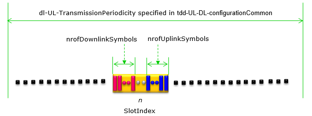
- The green double arrow across the top is
dl-UL-TransmissionPeriodicity . It comes from the common configuration rather than from this one. The dedicated element does not set the period, so the row of small slots below it is already fixed. - The one slot highlighted in yellow is the slot named by
slotIndex . Everything to its left and right stays as the common configuration left it. - Inside that slot, the symbols on the left under the first dashed arrow are counted by
nrofDownlinkSymbols , and they are always the leading symbols of the slot. - The symbols on the right are counted by
nrofUplinkSymbols , and they are always the trailing symbols. Neither count can start anywhere else. That is why two numbers describe the whole slot. - Whatever sits between the two runs is left flexible. A slot with no gap in the middle is written with
allDownlink orallUplink instead. No counts appear at all in that case.
The two counts grow inward from the two ends of the slot. That is the whole geometry of the explicit choice. The common configuration uses the same geometry for the whole period.
The IAB-MT Variant (Release 16)
An IAB node holds two radios rather than one. Its mobile termination behaves as a UE towards the parent node, and its distributed unit behaves as a gNB towards the UEs below it. Release 16 gave the mobile termination its own copy of this element, so that the two radios can be pointed in different directions at the same moment.
Following is based on
TDD-UL-DL-ConfigDedicated-IAB-MT-r16 ::=  SEQUENCE {
    slotSpecificConfigurationsToAddModList-IAB-MT-r16
                                        SEQUENCE (SIZE (1..maxNrofSlots))
                                            OF TDD-UL-DL-SlotConfig-IAB-MT-r16  OPTIONAL, -- Need N
    slotSpecificConfigurationsToReleaseList-IAB-MT-r16
                                        SEQUENCE (SIZE (1..maxNrofSlots))
                                            OF TDD-UL-DL-SlotIndex              OPTIONAL, -- Need N
    ...
}

TDD-UL-DL-SlotConfig-IAB-MT-r16 ::=  SEQUENCE {
    slotIndex-r16                           TDD-UL-DL-SlotIndex,
    symbols-IAB-MT-r16                      CHOICE {
        allDownlink-r16                         NULL,
        allUplink-r16                           NULL,
        explicit-r16                            SEQUENCE {
            nrofDownlinkSymbols-r16                 INTEGER (1..maxNrofSymbols-1)  OPTIONAL, -- Need S
            nrofUplinkSymbols-r16                   INTEGER (1..maxNrofSymbols-1)  OPTIONAL  -- Need S
        },
        explicit-IAB-MT-r16                     SEQUENCE {
            nrofDownlinkSymbols-r16                 INTEGER (1..maxNrofSymbols-1)  OPTIONAL, -- Need S
            nrofUplinkSymbols-r16                   INTEGER (1..maxNrofSymbols-1)  OPTIONAL  -- Need S
        }
    }
}
The outer structure is the same, field for field. The difference sits in the CHOICE, which carries
That second alternative is what a plain UE has no use for. An IAB node has to know both what its parent expects of it and what its own cell is doing, and one CHOICE alternative cannot carry both answers.
A list, not a pattern : the common element describes a whole period, and this one addresses individual slots by index. Slots not named are untouched.Three ways to describe a slot : all downlink, all uplink, or an explicit count at each end. The explicit choice leaves flexible symbols in the middle.Zero is written as absence : the counts begin at 1, so an omitted field is how a direction gets no symbols at all.Release restores, it does not blank : removing a slot configuration returns those symbols to the common configuration. They are not left undefined.An IAB node gets its own version :TDD-UL-DL-ConfigDedicated-IAB-MT-r16 repeats the structure for the mobile termination, and adds a second explicit alternative that a UE never needs.
How It Combines with the Common Configuration
A UE holding both elements has to reduce them to one answer per symbol. The order in which it does that is fixed. Reading a log is much easier once that order is clear. A symbol that looks wrongly configured is usually a symbol decided at a different layer.
Start with what the common configuration produces. It draws a period. It fixes a run of downlink symbols at the front and a run of uplink symbols at the back, and leaves the middle flexible. Those flexible symbols are the only material available to this element.
The dedicated element then names individual slots and spends some of that flexible material. 38.213 puts one more condition on the result, and it is easy to miss. The reference subcarrier spacing stays the one the common configuration provided. This element carries no reference SCS of its own. So a slot index here means a slot at the common numerology.
The outcome applies to every configured bandwidth part rather than to one of them. 38.213 says the slot configuration is common to each configured BWP. So moving a UE to another BWP does not change which symbols it may transmit in.
Whatever is still flexible after both elements have been read is handed to the physical layer. A DCI format 2_0 slot format indication resolves it for a group of UEs. An ordinary grant resolves it for one. So the four mechanisms run in a strict order of precedence.
Order |
Mechanism |
Scope |
What it may change |
|---|---|---|---|
1 |
tdd-UL-DL-ConfigurationCommon (SIB1) |
whole cell |
any symbol, since it draws the pattern first |
2 |
tdd-UL-DL-ConfigurationDedicated |
one UE |
flexible symbols only |
3 |
DCI format 2_0 |
a group of UEs |
symbols still flexible after 1 and 2 |
4 |
scheduling DCI |
one transmission |
symbols still flexible after 1, 2 and 3 |
Each row may only spend what the rows above it left flexible. That single rule keeps the cell coherent. It also allows one UE to be treated differently from its neighbours.
The note near the top of this page still holds, and it is worth repeating next to the table. Networks in the field configure rows 1, 3 and 4 routinely. Row 2 is the one rarely seen. The dynamic mechanisms can usually do its job, and they need no per-UE RRC reconfiguration to change.
Precedence runs from broad to narrow : cell, then UE, then group, then a single transmission. Each stage may only touch what the earlier ones left flexible.The numerology comes from the common element : this element carries no reference SCS. A slot index here is read at the common configuration’s subcarrier spacing.The result spans every BWP : the slot configuration is common to all configured bandwidth parts, so a BWP switch does not re-open the question.Rarely used, but not redundant : it is the only semi-static way to give one UE a different direction from its neighbours. A dynamic indication reaches the same result, but it has to signal every time.
Reference
[TS1] 3GPP TS 38.331 V19.3.0 - NR; RRC protocol specification. Source of the ASN.1 above
[TS2] 3GPP TS 38.213 - NR; Physical layer procedures for control. Clause 11.1 holds the precedence rules quoted on this page