A TDD carrier sends and receives on the same frequency, so every symbol has to belong to one direction or the other. This information element is where that split is written down, and it is broadcast, so every UE in the cell reads the same answer. The list below is the short version, and the sections after it work through each point.
|
- tdd UL/DL Common Configuration (tdd-UL-DL-configurationCommon) in Detail
- Rrc Parameters
- Transmission Periodicity
- What if TDD-UL-DL-ConfigCommon is not configured ?
- Guard Timing (Symbol gap for DL to UL switching)
- Why we need to consider Guard time only for DL to UL switching ?
- What would be the best guard time ?
- Any other consideration ?
- Subband Full Duplex (Release 19)
- Reference
- Get the Test Procedure and Log / Amarisoft TechAcademy
tdd UL/DL Common Configuration (tdd-UL-DL-configurationCommon) in Detail
When operating in TDD mode, we have to clearly define on exactly when to expect the transmission and when to expect the reception. In LTE TDD, we defined predefined pattern for UL and DL allocation in a radio frame. In 5G/NR, we don't have any predefined pattern. Instead, we can define the pattern in much more flexible way using several parameters as shown below.
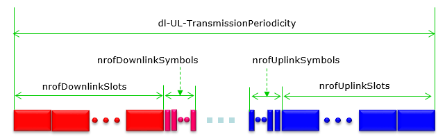
The four count fields work inward from the two ends of the period. The pale gap in the middle belongs to neither, and it is the only part of the pattern the network can still change from one slot to the next.
- The green arrow across the top is
dl-UL-TransmissionPeriodicity , and everything else is measured inside it. - The red blocks on the left are the
nrofDownlinkSlots full downlink slots, followed bynrofDownlinkSymbols downlink symbols at the front of the next slot. - The blue blocks on the right are the
nrofUplinkSlots full uplink slots, preceded bynrofUplinkSymbols uplink symbols at the end of the slot before them. - The pale squares between the two arrows are the flexible symbols. Setting the four counts so that this gap disappears is what the guard time discussion further down warns against.
Two patterns can be configured rather than one, and they run back to back inside a single period. That is what
Where the element is carried explains the word Common in its name. It sits in
A second element refines it per UE.
Common means broadcast, not merely shared : it arrives in SIB1, so a UE knows the frame layout before it has any dedicated configuration at all.It is conditional on TDD : the field carriesCond TDD in both parent elements, so an FDD cell simply does not include it.Dedicated refines, it does not override : only the flexible symbols are available to the per-UE element, which is why getting this pattern right matters for every UE in the cell at once.
Rrc Parameters
Five numbers describe a pattern, and they are counted from opposite ends. The downlink fields count forward from the start of the period and the uplink fields count backward from its end, so whatever neither claims is left flexible in the middle. That middle is where the guard period discussed further down comes from.
Following is based on
TDD-UL-DL-ConfigCommon ::= SEQUENCE { referenceSubcarrierSpacing SubcarrierSpacing, pattern1 TDD-UL-DL-Pattern, pattern2 TDD-UL-DL-Pattern OPTIONAL, -- Need R ... } TDD-UL-DL-Pattern ::= SEQUENCE { dl-UL-TransmissionPeriodicity ENUMERATED {ms0p5, ms0p625, ms1, ms1p25, ms2, ms2p5, ms5, ms10}, nrofDownlinkSlots INTEGER (0..maxNrofSlots), nrofDownlinkSymbols INTEGER (0..maxNrofSymbols-1), nrofUplinkSlots INTEGER (0..maxNrofSlots), nrofUplinkSymbols INTEGER (0..maxNrofSymbols-1), ..., [[ dl-UL-TransmissionPeriodicity-v1530 ENUMERATED {ms3, ms4} OPTIONAL -- Need R ]], [[sbfd-StartingSlotIndex-r19 INTEGER (0..maxNrofSlots-1) OPTIONAL, -- Need R sbfd-StartingSymbolIndex-r19 INTEGER (0..maxNrofSymbols-1) OPTIONAL, -- Need R sbfd-EndingSlotIndex-r19 INTEGER (0..maxNrofSlots-1) OPTIONAL, -- Need R sbfd-EndingSymbolIndex-r19 INTEGER (0..maxNrofSymbols-1) OPTIONAL -- Need R ]] } maxNrofSlots INTEGER ::= 320 -- Maximum number of slots in a 10 ms period maxNrofSymbols-1 INTEGER ::= 13 -- Maximum index identifying a symbol within a slot -- (14 symbols, indexed from 0..13)
Release 19 added four more fields, and they mark out a span rather than a count. Two give the slot and symbol where the SBFD region starts, and two give the slot and symbol where it ends.
sbfd-StartingSlotIndex-r19 sbfd-EndingSlotIndex-r19 sbfd-StartingSymbolIndex-r19 sbfd-EndingSymbolIndex-r19
Notice that all four are indices and not counts, which is the opposite convention to the five fields above them. The section on Subband Full Duplex explains what the marked span is for.
The two directions are counted from opposite ends : downlink forward from the start of the period, uplink backward from the end. Nothing counts the middle, and that is deliberate.Whatever is left over is flexible, not idle : the symbols neither side claims can be assigned dynamically, which is what the section on an unconfigured cell describes.The periodicity field has a replacement, not an addition : whendl-UL-TransmissionPeriodicity-v1530 is present the original field is ignored rather than combined with it.The reference SCS is not the data SCS : it exists only to fix the time boundaries, and every carrier on the cell has to agree on it whatever numerology it actually transmits with.
Transmission Periodicity
The applicable periodicity(P) of the UL/DL configuration varies depending on the reference numerology (n_ref). This can be summarized as a table as shown below. I created this table based on the descriptions in 38.213 v16.5 -11.1
|
P(ms) |
u_ref (scs Khz) |
Applicable u |
P/20 |
Number of Slots in a P |
||||
|
0 |
1 |
2 |
3 |
4 |
||||
|
0.5 |
Not described |
40 |
|
1 |
2 |
4 |
8 |
|
|
0.625 |
3(120) |
3 |
32 |
|
|
|
5 |
10 |
|
1.25 |
2(60), 3(120) |
2,3 |
16 |
|
|
5 |
10 |
20 |
|
2.5 |
1(30), 2(60), 3(120) |
1,2,3 |
8 |
|
5 |
10 |
20 |
40 |
|
5.0 |
Not described |
4 |
5 |
10 |
20 |
40 |
80 |
|
|
10.0 |
Not described |
2 |
10 |
20 |
40 |
80 |
160 |
|
One rule governs the whole table, and 38.213 states it in a single line: the UE expects the period to divide 20 ms. Everything in the P column follows from that, which is why 0.625, 1.25 and 2.5 appear alongside the round numbers and why 3 ms and 4 ms had to wait for a later release.
When two patterns are configured the rule applies to their
pattern1 + pattern2 |
Sum |
20 / sum |
Allowed |
|---|---|---|---|
0.5 + 0.5 | 1 ms | 20 | yes |
1 + 4 | 5 ms | 4 | yes |
2 + 3 | 5 ms | 4 | yes |
2.5 + 2.5 | 5 ms | 4 | yes |
3 + 3 | 6 ms | 3.33 | no |
4 + 4 | 8 ms | 2.5 | no |
Two periodicities that are each legal on their own can still be illegal together. 3 ms and 4 ms are the easiest pair to get wrong, because both are valid single values.
The reference SCS carries a second constraint. 38.213 requires it to be smaller than or equal to the SCS of every configured downlink and uplink BWP, and each slot the pattern describes then applies to as many consecutive slots of the active BWP as the numerology difference calls for. So a pattern written at 15 kHz still governs a 30 kHz BWP, and each of its slots covers two of them.
The period has to divide 20 ms : that single requirement explains every value in the enumeration, including the ones that look arbitrary.Two patterns are constrained by their sum : pattern1 and pattern2 can each be legal and still be rejected together. 3 ms with 3 ms is the classic example.The pattern is written in the coarsest numerology : the reference SCS cannot exceed any BWP SCS, so one pattern slot maps onto several real slots when the BWP uses a shorter one.
What if TDD-UL-DL-ConfigCommon is not configured ?
UE determines if each of the slot is uplink or downlink and the symbol allocation within each of the slot purely by DCIs as stated in 38.213-11.1 Slot configuration.
- the UE receives PDSCH or CSI-RS in the set of symbols of the slot if the UE receives a corresponding indication by a DCI format 1_0, DCI format 1_1, or DCI format 0_1
- the UE transmits PUSCH, PUCCH, PRACH, or SRS in the set of symbols of the slot if the UE receives a corresponding indication by a DCI format 0_0, DCI format 0_1, DCI format 1_0, DCI format 1_1, or DCI format 2_3
If a UE is not configured to monitor PDCCH for DCI format 2-0, for a set of symbols of a slot that are indicated as flexible by higher layer parameters TDD-UL-DL-ConfigurationCommon or TDD-UL-DL-ConfigDedicated, when provided to a UE, or
Read that condition carefully, because it names two different absences. One is this information element being absent altogether. The other is the element being present and marking a set of symbols as flexible, which is the ordinary case rather than an exception. Both leave the same question open, and both are answered by a DCI.
There is a second branch in the same clause, and it is the one that matters in a live network. A UE that
That layering is worth holding on to when reading a log. A symbol can be fixed by this broadcast element, overridden for one UE by the dedicated element, resolved for a group by DCI format 2_0, or left to an individual grant. Four mechanisms, and they are consulted in that order of precedence.
Absent and flexible are different states : an unconfigured cell leaves every symbol undetermined, while a configured cell usually leaves only the middle of the pattern undetermined.Flexible does not mean unusable : DCI format 2_0 exists precisely to fill in those symbols for a group of UEs, and a grant can fill them for one UE.Broadcast is the floor, not the whole answer : this element sets what every UE in the cell agrees on, and the dedicated configuration and the DCIs refine it from there.
Guard Timing (Symbol gap for DL to UL switching)
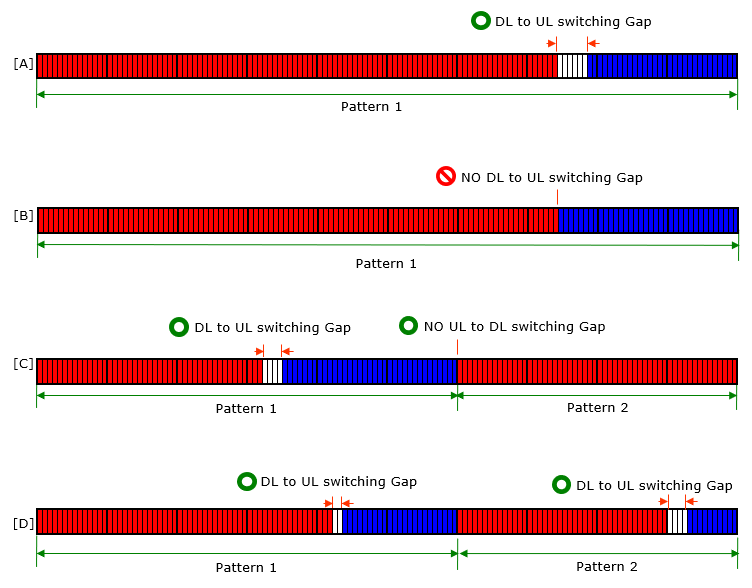
In terms of 3GPP RRC specification, you can set any values within the range of the values specified in RRC Parameter. However, in terms of lower layer perpective there is some restrictions (or something to take into account) as listed below.
- You need a certain number of Guard time (Guard symbols) when switches from DL to UL
- You don't need any guard time when switches from UL to DL
Followings are some of examples that are valid or invalid based on this rule.
Why we need to consider Guard time only for DL to UL switching ?
I think this question may be misleading a little bit. The question does imply that there is no need for the gap for DL to UL switching. In fact, the gap is required as in the case of UL to DL switching because of the physics. What this question implies that we may not need to take this gap into consideration in terms of PHY scheduling as illustrated in the illustration shown above. In this section, I will talk about why.
I don't think 3GPP TS document explicitely states about this requirement, but you may find some other documents (e.g, white papers) explaining about this requirement. Simply put, (You may refer to Recommendation 10 of Ref [1])
- we need some time for DL signal reach (propagate to) UE. So UE need some additional time from the end of DL signal. Otherwise, UE may transmit UL signal before it complete the reception of DL signal and as a result there would be interference between DL and UL signal.
- we don't need any guard time for UL to DL because DL and UL is always propery aligned thanks to timing advance. that is, gNB sends timing advance to make UL signal perfectly aligned in time domain.
Even though it is not clearly/explicitely stated, you may refer to 38.211 - 4.3.2 and following table :
< 38.211 - Table 4.3.2-3: Transition time NRx-Tx and NTx-Rx >

I had a chance to talk further on this subject with an L1 expert Sakshama Ghoslya . It was a productive chat and I thought it will be helpful for readers as well. Here I am sharing the chat with kind approval from Sakshama.
- Guard time for gNB DL to UL switch = 2 * Propagation delay + UE Rx to Tx switching delay
- Guard time for gNB UL to DL switch is also not zero. It is actually = gNB Rx to Tx switching delay that is equal to N_TA_offset*Tc.
- That's why there is a fixed PRACH timing advance provided = 25600 (for FR1) that is equal to 13us = 10us for gNB Rx to Tx switch + 3us for BTS to BTS synchronization.
- For FR2 it is 13792 that is equal to 7us = 3us for gNB Rx to Tx switch + 3us for BTS to BTS sync + 1us extra margin
38.104 - 9.5.3.2 Minimum requirement for BS type 1-O states as follows :
For BS type 1-O, the OTA transmitter transient period shall be shorter than the values listed in the minimum requirement as specified in following table.
< 38.104 - Table 9.5.3.2-1: Minimum requirement for the OTA transmitter transient period for BS type 1-O >

38.104 - 9.5.3.3 Minimum requirement for BS type 2-O states as follows :
< 38.104 - Table 9.5.3.3-1: Minimum requirement for the OTA transmitter transient period for BS type 2-O >

38.133-7.4.2 Minimum requirements states as follows:
The cell phase synchronization accuracy measured at BS antenna connectors shall be better than 3 μs.
Now as you see the above screenshot
N_TA_offset*Tc is nothing but = BS Tx activation time (Rx to Tx switch delay) + time to avoid BTS to BTS interference
-
N_TA_offset*Tc for FR1 = 10us + 3us = 13us
-
N_TA_offset*Tc for FR2 = 3us + 3us + 1us (extra) = 7us
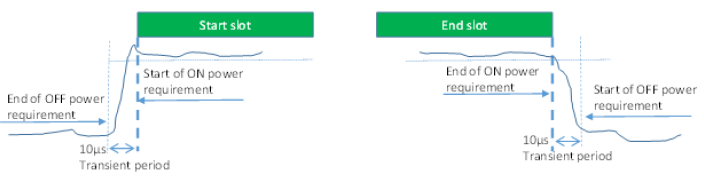
38.101-1 6.3.3.2 General ON/OFF time mask states as follows :
The general ON/OFF time mask defines the observation period between transmit OFF and ON power and between transmit ON and OFF power for each SCS. ON/OFF scenarios include: contiguous, and non-contiguous transmission, etc
The OFF power measurement period is defined in a duration of at least one slot excluding any transient periods. The ON power is defined as the mean power over one slot excluding any transient period.
< 38.101-1 Figure 6.3.3.2-1: General ON/OFF time mask for NR UL transmission in FR1 >
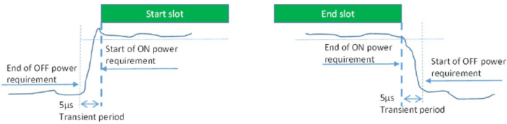
38.101-2 6.3.3.2 General ON/OFF time mask states as follows :
The general ON/OFF time mask defines the observation period allowed between transmit OFF and ON power. ON/OFF scenarios include: contiguous, and non-contiguous transmission, etc
The OFF power measurement period is defined in a duration of at least one slot excluding any transient periods. The ON power is defined as the mean power over one slot excluding any transient period.
< 38.101-2 Figure 6.3.3.2-1: General ON/OFF time mask for NR UL transmission in FR2 >
Another article supporting what I said is 5G synchronization requirements and solutions - Ericsson
What would be the best guard time ?
What would be the best Guard time (Symbol Gaps) ? The answer to this question would vary depending on various factors especially the distance between gNB and UE. Some guide line stated in Recommendation 10 of Ref [1]) is as follows.
- A GP(Guard Period) of 2 symbols would cater for cell sizes of up to 10.7 km;
- A GP(Guard Period) of 4 symbols would cater for cell sizes of up to 21.4 km;
- A GP(Guard Period) of 6 symbols would cater for cell sizes of up to 32.1 km.
Any other consideration ?
This is not directly related to Guard time, but you need to make it sure that the PRACH Occasion you set in RACH config should fall into the UL slot/symbols you configured in the RRC.
Subband Full Duplex (Release 19)
Everything above this heading assumes one thing: at any instant the carrier points in one direction. That assumption is what forces the guard period, and it is what caps how often a UE gets an uplink opportunity. Release 19 relaxes it, and the four new fields in the pattern above are where the relaxation is configured.
Subband full duplex splits the carrier in frequency instead of in time. Inside a symbol that would otherwise be downlink, a slice of the band is given to the uplink, and the gNB transmits and receives at the same moment on different frequencies. The UE still does one thing at a time, so this is a base station capability rather than a UE one.
Two separate pieces of configuration are needed, and they sit in different information elements.
Question |
Answered by |
Where it lives |
|---|---|---|
Which symbols of the period are SBFD symbols |
TDD-UL-DL-Pattern |
|
How the band is divided inside those symbols |
SCS-SpecificCarrier |
The time question stays with the TDD pattern, where the rest of this page lives. The frequency question moves to the carrier definition, because a subband split is a property of the carrier rather than of the pattern.
The naming of the second row tells you the shape. One uplink subband, and up to two downlink subbands, so the intended arrangement is a downlink slice on each side of an uplink slice in the middle. The uplink is guarded on both flanks by the operator’s own downlink rather than by an empty gap.
38.213 clause 11.1 states the same thing from the other end, and it also settles which symbols may carry a subband. A downlink or flexible symbol provided by this information element can include an uplink subband and a first downlink subband. It may additionally include a second downlink subband. Uplink symbols are not mentioned, because an uplink symbol is already entirely uplink.
Downstream of these two elements, a good deal of the rest of the specification has to be told that SBFD symbols exist. Random access is one example. 38.331 defines a single and a dual RACH configuration for SBFD operation, so that preambles can be sent in SBFD symbols rather than only in ordinary uplink ones. Power control is another, with separate parameter sets selected when the transmission falls in SBFD symbols.
Scheduling restrictions are the third. By default a downlink assignment is confined to SBFD symbols only or to non-SBFD symbols only, and
The split is in frequency, not in time : an SBFD symbol still belongs to the TDD period drawn above, but part of its bandwidth is uplink while the rest stays downlink.The four new fields mark a span, not a count : a starting slot and symbol and an ending slot and symbol, unlike the five fields above them which are counts inward from each end.Time and frequency are configured in different places : the pattern says which symbols, and SCS-SpecificCarrier says how the band is cut inside them.One uplink subband, up to two downlink : the field names carry the intended layout, with the uplink slice between two downlink slices.It does not remove the guard period : a cell still switches direction at the pattern boundaries, so everything in the section above still applies to the symbols that are not SBFD.
Reference
[TS1] 3GPP TS 38.331 V19.3.0 - NR; RRC protocol specification. Source of the ASN.1 above, including the Release 19 SBFD extension group
[TS2] 3GPP TS 38.213 - NR; Physical layer procedures for control. Clause 11.1 holds the slot configuration rules quoted on this page
[TS3] 3GPP TS 38.211 - NR; Physical channels and modulation. Table 4.3.2-3 gives the transition times
[1] 5G TDD Synchronisation Guidelines and Recommendations for the Coexistence of TDD Networks in the 3.5 GHz Range - GSMA (2020)
[2] 5G TDD Uplink White Paper - NGMN (2022)
[3] TDD : Why a Guard Period only in DL-to-UL Switching ? - TECHTRAINED